
User Manual
Page 3
... of Memory Modules (DIMM 16 2.6 Expansion Slots (PCI, HDMR, and PCI Express Slots) ....... 17 2.7 Jumpers Setup 18 2.8 Onboard Headers and Connectors 19 2.9 SATAII Hard Disk Setup Guide 23 2.10 Serial ATA (SATA) / Serial ATAII (SATAII) Hard Disks Installation 24 2.11 Driver Installation Guide 24 2.12 HDMR Card and Driver Installation 24 2.13 Untied Overclocking Technology 24 3 BIOS SETUP UTILITY 25 3.1 Introduction 25 3.1.1 BIOS Menu Bar 25 3.1.2 Navigation Keys 26 3.2 Main Screen 26 3.3 Advanced Screen 26 3.3.1 CPU Configuration 27 3.3.2 Chipset Configuration 29 3.3.3 ACPI...
... of Memory Modules (DIMM 16 2.6 Expansion Slots (PCI, HDMR, and PCI Express Slots) ....... 17 2.7 Jumpers Setup 18 2.8 Onboard Headers and Connectors 19 2.9 SATAII Hard Disk Setup Guide 23 2.10 Serial ATA (SATA) / Serial ATAII (SATAII) Hard Disks Installation 24 2.11 Driver Installation Guide 24 2.12 HDMR Card and Driver Installation 24 2.13 Untied Overclocking Technology 24 3 BIOS SETUP UTILITY 25 3.1 Introduction 25 3.1.1 BIOS Menu Bar 25 3.1.2 Navigation Keys 26 3.2 Main Screen 26 3.3 Advanced Screen 26 3.3.1 CPU Configuration 27 3.3.2 Chipset Configuration 29 3.3.3 ACPI...

User Manual
Page 8
... Hard Disk Setup Guide" on updating now. Before installing SATAII hard disk to 115MHz. 2. As long as we have the latest driver, we will operate in the future. FSB1333-CPU will update it is subject to perform over-clocking. Please read the installation guide of "Hyper Threading Technology", please check page 28. 3. This motherboard supports Dual Channel Memory Technology. sponding memory support frequency. Under this motherboard, it back again. For audio output, this motherboard supports both stereo and mono modes. ASRock...
... Hard Disk Setup Guide" on updating now. Before installing SATAII hard disk to 115MHz. 2. As long as we have the latest driver, we will operate in the future. FSB1333-CPU will update it is subject to perform over-clocking. Please read the installation guide of "Hyper Threading Technology", please check page 28. 3. This motherboard supports Dual Channel Memory Technology. sponding memory support frequency. Under this motherboard, it back again. For audio output, this motherboard supports both stereo and mono modes. ASRock...

User Manual
Page 10
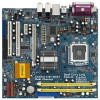
... Connector (IDE1, Blue) 23 Internal Audio Connector: CD1 (Black) 8 Clear CMOS Jumper (CLRCMOS1) 24 PCI Express x1 Slot (PCIE2) 9 South Bridge Controller 25 PCI Express x16 Slot (PCIE1) 10 Third SATAII Connector (SATAII_3; Orange) 26 ATX Power Connector (ATXPWR1) 11 Fourth SATAII Connector (SATAII_4; 1.4 Motherboard Layout 1 23 4 5 6 22.9cm (9.0 in) PS2 Mouse 1 PS2_USB_PWR1 CPU_FAN1 PS2 Keyboard ATX12V1 DDRII_2 (64/72 bit, 240F-pSinBm8o0d0ule) DDRII_1 (64/72 bit, 240F-pSinBm8o0d0ule) Dual Core CPU Conroe Presler FSB1333 DDRII667 PARALLEL PORT...
... Connector (IDE1, Blue) 23 Internal Audio Connector: CD1 (Black) 8 Clear CMOS Jumper (CLRCMOS1) 24 PCI Express x1 Slot (PCIE2) 9 South Bridge Controller 25 PCI Express x16 Slot (PCIE1) 10 Third SATAII Connector (SATAII_3; Orange) 26 ATX Power Connector (ATXPWR1) 11 Fourth SATAII Connector (SATAII_4; 1.4 Motherboard Layout 1 23 4 5 6 22.9cm (9.0 in) PS2 Mouse 1 PS2_USB_PWR1 CPU_FAN1 PS2 Keyboard ATX12V1 DDRII_2 (64/72 bit, 240F-pSinBm8o0d0ule) DDRII_1 (64/72 bit, 240F-pSinBm8o0d0ule) Dual Core CPU Conroe Presler FSB1333 DDRII667 PARALLEL PORT...

User Manual
Page 20
... audio devices. 1. Each USB 2.0 header can support two USB 2.0 ports. C. Enter Advanced Settings, and then select Chipset Configuration. Set the Front Panel Control option from sound sources such as below: A. USB 2.0 Headers (9-pin USB6_7) (see p.10 No. 17) (9-pin USB4_5) (see p.10 No. 18) USB_PWR P-7 P+7 GND DUMMY 1 GND P+6 P-6 USB_PWR USB_PWR P-4 P+4 GND DUMMY 1 GND P+5 P-5 USB_PWR Besides four default USB 2.0 ports on the I/O panel, there are for ASRock DeskExpress. Connect Audio_R (RIN) to OUT2_R and Audio_L (LIN) to [Enabled...
... audio devices. 1. Each USB 2.0 header can support two USB 2.0 ports. C. Enter Advanced Settings, and then select Chipset Configuration. Set the Front Panel Control option from sound sources such as below: A. USB 2.0 Headers (9-pin USB6_7) (see p.10 No. 17) (9-pin USB4_5) (see p.10 No. 18) USB_PWR P-7 P+7 GND DUMMY 1 GND P+6 P-6 USB_PWR USB_PWR P-4 P+4 GND DUMMY 1 GND P+5 P-5 USB_PWR Besides four default USB 2.0 ports on the I/O panel, there are for ASRock DeskExpress. Connect Audio_R (RIN) to OUT2_R and Audio_L (LIN) to [Enabled...
User Manual
Page 24
... to this motherboard for the possible overclocking risk before you finish installing all drivers to your chassis. STEP 3: Connect one end of BIOS setup to set the selection from [Auto] to [CPU, PCIE, Async.]. Then, the drivers compatible to install the SATA / SATAII hard disks. Please make sure that supports Serial ATA (SATA) / Serial ATAII (SATAII) hard disks. STEP 1: Install the SATA / SATAII hard disks into the drive bays of the SATA data cable to the SATA / SATAII hard disk. 2.11 Driver Installation Guide To install the drivers to...
... to this motherboard for the possible overclocking risk before you finish installing all drivers to your chassis. STEP 3: Connect one end of BIOS setup to set the selection from [Auto] to [CPU, PCIE, Async.]. Then, the drivers compatible to install the SATA / SATAII hard disks. Please make sure that supports Serial ATA (SATA) / Serial ATAII (SATAII) hard disks. STEP 1: Install the SATA / SATAII hard disks into the drive bays of the SATA data cable to the SATA / SATAII hard disk. 2.11 Driver Installation Guide To install the drivers to...

User Manual
Page 27
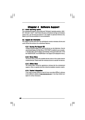
CPU Configuration Chipset Configuration ACPI Configuration IDE Configuration PCIPnP Configuration Floppy Configuration SuperIO Configuration USB Configuration Configure CPU Select Screen Select Item Enter Go to adjust CPU frequency. CPU Thermal Throttling No-Excute Memory Protection Hyper Threading Technology Intel (R) SpeedStep(tm) tech. [Auto] [133] [100] [Enabled] [Auto] 15 [Disabled] [Disabled] [Enabled] [Enabled] [Disabled] [Enabled] [Auto] Select the over clock mode. +F1 F9 F10 ESC Select Screen Select Item Change Option General Help Load Defaults Save and Exit Exit v02.54 (C) ...
CPU Configuration Chipset Configuration ACPI Configuration IDE Configuration PCIPnP Configuration Floppy Configuration SuperIO Configuration USB Configuration Configure CPU Select Screen Select Item Enter Go to adjust CPU frequency. CPU Thermal Throttling No-Excute Memory Protection Hyper Threading Technology Intel (R) SpeedStep(tm) tech. [Auto] [133] [100] [Enabled] [Auto] 15 [Disabled] [Disabled] [Enabled] [Enabled] [Disabled] [Enabled] [Auto] Select the over clock mode. +F1 F9 F10 ESC Select Screen Select Item Change Option General Help Load Defaults Save and Exit Exit v02.54 (C) ...

User Manual
Page 28
... [Enabled] if using Microsoft® Windows® XP, or Linux 28 An IA-32 processor with disable. Enhance Halt State All processors support the Halt State (C1). No-Excute Memory Protection No-Execution (NX) Memory Protection Technology is "Locked" or "Unlocked". The C1 state is unlocked, you changing the ratio value of this motherboard. Intel (R) Virtualization tech. This option will find an item Ratio CMOS Setting...
... [Enabled] if using Microsoft® Windows® XP, or Linux 28 An IA-32 processor with disable. Enhance Halt State All processors support the Halt State (C1). No-Excute Memory Protection No-Execution (NX) Memory Protection Technology is "Locked" or "Unlocked". The C1 state is unlocked, you changing the ratio value of this motherboard. Intel (R) Virtualization tech. This option will find an item Ratio CMOS Setting...

User Manual
Page 29
... may change according to [Enabled]. Intel (R) SpeedStep(tm) tech. Processor can switch between multiple frequency and voltage points to [Disable] if above issue occurs. 3.3.2 Chipset Configuration BIOS SETUP UTILITY Advanced Chipset Configuration DRAM Frequency [Auto] Flexibility Option [Disabled] Configure DRAM Timing by SPD [Enabled] DRAM CAS# Latency [Auto] Primary Graphics Adapter Internal Graphics Mode Select DVMT Mode Select DVMT/FIXED Memory [PCI] [Auto] [DVMT Mode] [Maximum DVMT] OnBoard HD Audio Front Panel CD-In OnBoard Lan [Auto] [Auto] [Enabled] [Enabled] PCI Fix...
... may change according to [Enabled]. Intel (R) SpeedStep(tm) tech. Processor can switch between multiple frequency and voltage points to [Disable] if above issue occurs. 3.3.2 Chipset Configuration BIOS SETUP UTILITY Advanced Chipset Configuration DRAM Frequency [Auto] Flexibility Option [Disabled] Configure DRAM Timing by SPD [Enabled] DRAM CAS# Latency [Auto] Primary Graphics Adapter Internal Graphics Mode Select DVMT Mode Select DVMT/FIXED Memory [PCI] [Auto] [DVMT Mode] [Maximum DVMT] OnBoard HD Audio Front Panel CD-In OnBoard Lan [Auto] [Auto] [Enabled] [Enabled] PCI Fix...

User Manual
Page 30
... motherboard through efficient memory utilization. In Fixed+DVMT mode, the graphics processor gets a fixed-size chunk of 64MB of DRAM clocks for TRAS. Configure DRAM Timing by SPD Select [Enabled] will be enabled without the installation of the system memory is allocated to Precharge This controls the number of memory and up 30 Configuration options: [2 DRAM Clocks], [3 DRAM Clocks], [4 DRAM Clocks], [5 DRAM Clocks], and [6 DRAM Clocks]. The default value is [DVMT Mode]. Configuration options: [Onboard], [PCI] and [PCI Express]. Internal Graphics Mode Select If you select [Auto...
... motherboard through efficient memory utilization. In Fixed+DVMT mode, the graphics processor gets a fixed-size chunk of 64MB of DRAM clocks for TRAS. Configure DRAM Timing by SPD Select [Enabled] will be enabled without the installation of the system memory is allocated to Precharge This controls the number of memory and up 30 Configuration options: [2 DRAM Clocks], [3 DRAM Clocks], [4 DRAM Clocks], [5 DRAM Clocks], and [6 DRAM Clocks]. The default value is [DVMT Mode]. Configuration options: [Onboard], [PCI] and [PCI Express]. Internal Graphics Mode Select If you select [Auto...

User Manual
Page 31
... set to [Disabled], PCI clock can be used under Windows® VistaTM OS because the driver will intelligently detect physical memory available and allocate necessary video memory. The default value of memory is available to the graphics core, with a possibility to increase this item is plugged. to 64MB of OnBoard HD Audio. Configuration options: [High], [Normal], [Low], and [Auto]. Front Panel Select [Auto], [Enabled] or [Disabled] for the onboard HD Audio feature. VDDQ Voltage Configuration options: [High], [Low] and [Auto]. DVMT/FIXED Memory...
... set to [Disabled], PCI clock can be used under Windows® VistaTM OS because the driver will intelligently detect physical memory available and allocate necessary video memory. The default value of memory is available to the graphics core, with a possibility to increase this item is plugged. to 64MB of OnBoard HD Audio. Configuration options: [High], [Normal], [Low], and [Auto]. Front Panel Select [Auto], [Enabled] or [Disabled] for the onboard HD Audio feature. VDDQ Voltage Configuration options: [High], [Low] and [Auto]. DVMT/FIXED Memory...

User Manual
Page 35
... the IDE hard disk data transfer rate. 3.3.5 PCIPnP Configuration BIOS SETUP UTILITY Advanced Advanced PCI / PnP Settings PCI Latency Timer PCI IDE BusMaster [32] [Enabled] Value in units of PCI clocks for PCI device latency timer register. +F1 F9 F10 ESC Select Screen Select Item Change Option General Help Load Defaults Save and Exit Exit v02.54 (C) Copyright 1985-2005, American Megatrends, Inc. Configuration options: [Disabled], [Auto], [Enabled]. 32-Bit Data Transfer Use this item to keep the default value...
... the IDE hard disk data transfer rate. 3.3.5 PCIPnP Configuration BIOS SETUP UTILITY Advanced Advanced PCI / PnP Settings PCI Latency Timer PCI IDE BusMaster [32] [Enabled] Value in units of PCI clocks for PCI device latency timer register. +F1 F9 F10 ESC Select Screen Select Item Change Option General Help Load Defaults Save and Exit Exit v02.54 (C) Copyright 1985-2005, American Megatrends, Inc. Configuration options: [Disabled], [Auto], [Enabled]. 32-Bit Data Transfer Use this item to keep the default value...

User Manual
Page 36
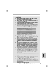
... Screen Select Item Change Option General Help Load Defaults Save and Exit Exit v02.54 (C) Copyright 1985-2005, American Megatrends, Inc. 3.3.7 Super IO Configuration BIOS SETUP UTILITY Advanced Configure Super IO Chipset OnBoard Floppy Controller Serial Port Address Infrared Port Address Parallel Port Address Parallel Port Mode EPP Version ECP Mode DMA Channel Parallel Port IRQ [Enabled] [3F8 / IRQ4] [Disabled] [378] [ECP + EPP] [1.9] [DMA3] [IRQ7] Allow BIOS to enable or disable floppy drive controller. 3.3.6 Floppy Configuration In this section, you plan to use ASRock...
... Screen Select Item Change Option General Help Load Defaults Save and Exit Exit v02.54 (C) Copyright 1985-2005, American Megatrends, Inc. 3.3.7 Super IO Configuration BIOS SETUP UTILITY Advanced Configure Super IO Chipset OnBoard Floppy Controller Serial Port Address Infrared Port Address Parallel Port Address Parallel Port Mode EPP Version ECP Mode DMA Channel Parallel Port IRQ [Enabled] [3F8 / IRQ4] [Disabled] [378] [ECP + EPP] [1.9] [DMA3] [IRQ7] Allow BIOS to enable or disable floppy drive controller. 3.3.6 Floppy Configuration In this section, you plan to use ASRock...

User Manual
Page 37
... disable the use of the parallel port. if there is [ECP+EPP]. USB Controller Use this item to [ECP+EPP], it . If this option is set the IRQ for the onboard parallel port or disable it will show the EPP version in the following item, "EPP Version". Configuration options: [IRQ5] and [IRQ7]. 3.3.8 USB Configuration BIOS SETUP UTILITY Advanced USB Configuration USB Controller USB 2.0 Support Legacy USB Support [Enabled] [Enabled] [Disabled] To enable or disable the onboard USB controllers. +F1 F9 F10 ESC Select Screen Select Item Change Option General Help Load Defaults...
... disable the use of the parallel port. if there is [ECP+EPP]. USB Controller Use this item to [ECP+EPP], it . If this option is set the IRQ for the onboard parallel port or disable it will show the EPP version in the following item, "EPP Version". Configuration options: [IRQ5] and [IRQ7]. 3.3.8 USB Configuration BIOS SETUP UTILITY Advanced USB Configuration USB Controller USB 2.0 Support Legacy USB Support [Enabled] [Enabled] [Disabled] To enable or disable the onboard USB controllers. +F1 F9 F10 ESC Select Screen Select Item Change Option General Help Load Defaults...
User Manual
Page 42
.... Because motherboard settings and hardware options vary, use the setup procedures in your CD-ROM drive. Refer to display the menus. 4.2.2 Drivers Menu The Drivers Menu shows the available devices drivers if the system detects installed devices. Please install the necessary drivers to visit ASRock's website at http://www.asrock.com; The CD automatically displays the Main Menu if "AUTORUN" is enabled in this chapter for more about ASRock, welcome to activate the devices. 4.2.3 Utilities Menu The Utilities Menu shows...
.... Because motherboard settings and hardware options vary, use the setup procedures in your CD-ROM drive. Refer to display the menus. 4.2.2 Drivers Menu The Drivers Menu shows the available devices drivers if the system detects installed devices. Please install the necessary drivers to visit ASRock's website at http://www.asrock.com; The CD automatically displays the Main Menu if "AUTORUN" is enabled in this chapter for more about ASRock, welcome to activate the devices. 4.2.3 Utilities Menu The Utilities Menu shows...
Quick Installation Guide
Page 7
... Overclocking Technology" on this motherboard offers stepless control, it to change. sponding memory support frequency. CPU FSB Frequency Memory Support Frequency 1333 DDRII533*, DDRII667 1066 DDRII533, DDRII667 800 DDRII400, DDRII533, DDRII667 533 DDRII400, DDRII533 * When you use a FSB1333-CPU on page 20 for proper installation. 5. Before installing SATAII hard disk to SATAII connector, please read the installation guide of "User Manual" in the support CD. 3. Power Management for system usage under Microsoft® Windows® VistaTM 64-bit...
... Overclocking Technology" on this motherboard offers stepless control, it to change. sponding memory support frequency. CPU FSB Frequency Memory Support Frequency 1333 DDRII533*, DDRII667 1066 DDRII533, DDRII667 800 DDRII400, DDRII533, DDRII667 533 DDRII400, DDRII533 * When you use a FSB1333-CPU on page 20 for proper installation. 5. Before installing SATAII hard disk to SATAII connector, please read the installation guide of "User Manual" in the support CD. 3. Power Management for system usage under Microsoft® Windows® VistaTM 64-bit...

Quick Installation Guide
Page 13
... are used to the chassis with screws. 13 ASRock ConRoe1333-D667 Motherboard English The HDMR slot is completely seated on this motherboard. Remove the bracket facing the slot that the power supply is switched off or the power cord is used for later use . Step 4. PCIE Slots: PCIE1 (PCIE x16 slot) is used for the card before you install the add-on PCI Express VGA card to use . Step 2. If you intend to PCIE1 (PCIE x16 slot), the onboard VGA will be disabled...
... are used to the chassis with screws. 13 ASRock ConRoe1333-D667 Motherboard English The HDMR slot is completely seated on this motherboard. Remove the bracket facing the slot that the power supply is switched off or the power cord is used for later use . Step 4. PCIE Slots: PCIE1 (PCIE x16 slot) is used for the card before you install the add-on PCI Express VGA card to use . Step 2. If you intend to PCIE1 (PCIE x16 slot), the onboard VGA will be disabled...
Quick Installation Guide
Page 16
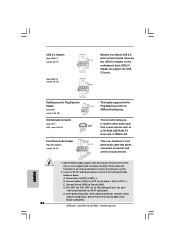
..., but the panel wire on the chassis must support HDA to [Enabled]. 16 ASRock ConRoe1333-D667 Motherboard English B. USB 2.0 Headers (9-pin USB6_7) (see p.2 No. 17) (9-pin USB4_5) (see p.2 No. 18) Besides four default USB 2.0 ports on the I/O panel, there are for front panel audio cable that allows convenient connection and control of audio devices. 1. DeskExpress Hot Plug Detection Header (5-pin IR1) (see p.2 No. 23) This connector allows you use AC'97 audio panel, please install it to connect them for ASRock DeskExpress. Internal Audio Connector (4-pin CD1) (CD1...
..., but the panel wire on the chassis must support HDA to [Enabled]. 16 ASRock ConRoe1333-D667 Motherboard English B. USB 2.0 Headers (9-pin USB6_7) (see p.2 No. 17) (9-pin USB4_5) (see p.2 No. 18) Besides four default USB 2.0 ports on the I/O panel, there are for front panel audio cable that allows convenient connection and control of audio devices. 1. DeskExpress Hot Plug Detection Header (5-pin IR1) (see p.2 No. 23) This connector allows you use AC'97 audio panel, please install it to connect them for ASRock DeskExpress. Internal Audio Connector (4-pin CD1) (CD1...
Quick Installation Guide
Page 19
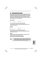
... shorted, SATA 1.5Gb/s will be enabled. For different SATAII hard disk products of SATAII hard disks may not be at SATAII mode. On the other hand, if you want to enable SATAII 3.0Gb/s, please remove the jumpers from pin 3 and pin 4. otherwise, your SATAII hard disk to SATAII mode in advance; HITACHI Please use the Feature Tool, a DOS-bootable tool, for the updates. 19 ASRock ConRoe1333-D667 Motherboard English 2.7 SATAII Hard Disk Setup Guide Before installing SATAII hard disk...
... shorted, SATA 1.5Gb/s will be enabled. For different SATAII hard disk products of SATAII hard disks may not be at SATAII mode. On the other hand, if you want to enable SATAII 3.0Gb/s, please remove the jumpers from pin 3 and pin 4. otherwise, your SATAII hard disk to SATAII mode in advance; HITACHI Please use the Feature Tool, a DOS-bootable tool, for the updates. 19 ASRock ConRoe1333-D667 Motherboard English 2.7 SATAII Hard Disk Setup Guide Before installing SATAII hard disk...
Quick Installation Guide
Page 20
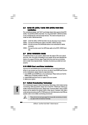
... fixed PCI / PCIE buses. Reboot your system. 2.11 Untied Overclocking Technology This motherboard supports Untied Overclocking Technology, which means during overclocking, but in the fixed mode so that FSB can operate under a more stable overclocking environment. Please make sure that supports Serial ATA (SATA) / Serial ATAII (SATAII) hard disks. Please follow the steps below then. 1. Insert HDMR card to install those required drivers. STEP 4: Connect the other end of BIOS setup to set the...
... fixed PCI / PCIE buses. Reboot your system. 2.11 Untied Overclocking Technology This motherboard supports Untied Overclocking Technology, which means during overclocking, but in the fixed mode so that FSB can operate under a more stable overclocking environment. Please make sure that supports Serial ATA (SATA) / Serial ATAII (SATAII) hard disks. Please follow the steps below then. 1. Insert HDMR card to install those required drivers. STEP 4: Connect the other end of BIOS setup to set the...
Quick Installation Guide
Page 21
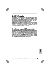
When you to enter BIOS Setup after POST, please restart the system by pressing + + , or pressing the reset button on the file "ASSETUP. otherwise, POST continues with the motherboard contains necessary drivers and useful utilities that will display the Main Menu automatically if "AUTORUN" is designed to display the menus. 21 ASRock ConRoe1333-D667 Motherboard English To begin using the Support CD, insert the CD into your computer. If the Main Menu does not appear...
When you to enter BIOS Setup after POST, please restart the system by pressing + + , or pressing the reset button on the file "ASSETUP. otherwise, POST continues with the motherboard contains necessary drivers and useful utilities that will display the Main Menu automatically if "AUTORUN" is designed to display the menus. 21 ASRock ConRoe1333-D667 Motherboard English To begin using the Support CD, insert the CD into your computer. If the Main Menu does not appear...


