
User Manual
Page 2
...damages for any interference received, including interference that may cause undesired operation. Operation is subject to the contents of this motherboard contains Perchlorate, a toxic substance controlled in advance. "Perchlorate Material-special handling may not be liable for identification or...contained in this documentation may or may apply, see www.dtsc.ca.gov/hazardouswaste/ perchlorate" ASRock Website: http://www.asrock.com ASRock assumes no event shall ASRock, its directors, officers, employees, or agents be registered trademarks or copyrights of their respective ...
...damages for any interference received, including interference that may cause undesired operation. Operation is subject to the contents of this motherboard contains Perchlorate, a toxic substance controlled in advance. "Perchlorate Material-special handling may not be liable for identification or...contained in this documentation may or may apply, see www.dtsc.ca.gov/hazardouswaste/ perchlorate" ASRock Website: http://www.asrock.com ASRock assumes no event shall ASRock, its directors, officers, employees, or agents be registered trademarks or copyrights of their respective ...

User Manual
Page 4
Contents Chapter 1 Introduction 1 1.1 Package Contents 1 1.2 Specifications 2 Chapter 2 Product Overview 4 2.1 Front View 4 2.2 Rear View 5 2.3 Motherboard Layout 6 Chapter 3 Hardware Installation 12 3.1 Begin Installation 12 3.2 Installing the CPU 13 3.3 Installing the CPU Fan and Heatsink 15 3.4 Installing Memory Modules (SO-DIMM)...3.7 Installing the 2.5-inch HDD/SSD 19 3.8 Complete 21 3.9 Installing the VESA Bracket (Optional) 22 Chapter 3 Software and Utilities Operation 24 3.1 Installing Drivers 24 3.2 ASRock Live Update & APP Shop 25 3.2.1 UI Overview 25
Contents Chapter 1 Introduction 1 1.1 Package Contents 1 1.2 Specifications 2 Chapter 2 Product Overview 4 2.1 Front View 4 2.2 Rear View 5 2.3 Motherboard Layout 6 Chapter 3 Hardware Installation 12 3.1 Begin Installation 12 3.2 Installing the CPU 13 3.3 Installing the CPU Fan and Heatsink 15 3.4 Installing Memory Modules (SO-DIMM)...3.7 Installing the 2.5-inch HDD/SSD 19 3.8 Complete 21 3.9 Installing the VESA Bracket (Optional) 22 Chapter 3 Software and Utilities Operation 24 3.1 Installing Drivers 24 3.2 ASRock Live Update & APP Shop 25 3.2.1 UI Overview 25
User Manual
Page 6
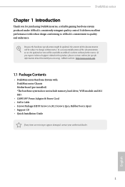
..., a reliable gaming barebone system produced under ASRock's consistently stringent quality control. In case any items are using. DeskMini series Chapter 1 Introduction Thank you for specific information about the model you require technical support related to quality and endurance. It delivers excellent performance with : DeskMini series Chassis Motherboard (pre-installed) *The barebone system does not...
..., a reliable gaming barebone system produced under ASRock's consistently stringent quality control. In case any items are using. DeskMini series Chapter 1 Introduction Thank you for specific information about the model you require technical support related to quality and endurance. It delivers excellent performance with : DeskMini series Chassis Motherboard (pre-installed) *The barebone system does not...

User Manual
Page 7
TDP 65W) CPU cooling • Supports Standard Intel Box Fan Coolers Motherboard • ASRock H110M-STX (Mini-STX) Chipset • Intel® H110 Intel® H170 Chipset (Optional); Intel® B150 Chipset... (Type-C), 1 x Headphone/Headset Jack , 1 x MIC-In Rear I/O • 1 x VGA , 1 x HDMI, 1 x DP, 1 x USB 3.0, 1 x USB 2.0, 1 x LAN, 1 x DC-In Jack 2 English 1.2 Specifications System Model • DeskMini 110 Chassis CPU • 1.92L (155 x 155 x 80mm) • Supports 6th Generation Intel® CoreTM i7/i5/i3/Pentium®/ Celeron® Processors (Max. Intel®...
TDP 65W) CPU cooling • Supports Standard Intel Box Fan Coolers Motherboard • ASRock H110M-STX (Mini-STX) Chipset • Intel® H110 Intel® H170 Chipset (Optional); Intel® B150 Chipset... (Type-C), 1 x Headphone/Headset Jack , 1 x MIC-In Rear I/O • 1 x VGA , 1 x HDMI, 1 x DP, 1 x USB 3.0, 1 x USB 2.0, 1 x LAN, 1 x DC-In Jack 2 English 1.2 Specifications System Model • DeskMini 110 Chassis CPU • 1.92L (155 x 155 x 80mm) • Supports 6th Generation Intel® CoreTM i7/i5/i3/Pentium®/ Celeron® Processors (Max. Intel®...
User Manual
Page 11
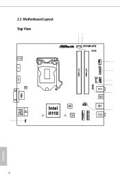
2.3 Motherboard Layout Top View 12 DC Jack DP1 HDMI1 Audio CODEC VGA1 USB 2.0 T: USB3 Top: USB 3.0 RJ-45 B: USB4 9 1 CI1 H110M-STX CPU_FAN2 RoHS DDR4_A1 DDR4_B1 3 CPU_FAN1 1 4 LPC1 SPEAKER1 USB_5_6 1 5 1 COM1 6 1 Mic In 7 USB 3.0 USB_2 Intel H110 M2_1_CT1 BIOS ROM M2_2_CT1 Super I/O PANEL1 PLED PWRBTN 1 HDLED RESET USB 3.0 USB_1 8 Headphone / Headset M.2 WiFi M.2 PCIe SSD English 6
2.3 Motherboard Layout Top View 12 DC Jack DP1 HDMI1 Audio CODEC VGA1 USB 2.0 T: USB3 Top: USB 3.0 RJ-45 B: USB4 9 1 CI1 H110M-STX CPU_FAN2 RoHS DDR4_A1 DDR4_B1 3 CPU_FAN1 1 4 LPC1 SPEAKER1 USB_5_6 1 5 1 COM1 6 1 Mic In 7 USB 3.0 USB_2 Intel H110 M2_1_CT1 BIOS ROM M2_2_CT1 Super I/O PANEL1 PLED PWRBTN 1 HDLED RESET USB 3.0 USB_1 8 Headphone / Headset M.2 WiFi M.2 PCIe SSD English 6
User Manual
Page 14
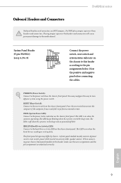
...the pin assignments below. Press the reset switch to restart the computer if the computer freezes and fails to this header according to the motherboard. The front panel design may configure the way to turn off (S5). When connecting your system using the power switch. The LED... is on when the hard drive is operating. DeskMini series Onboard Headers and Connectors Onboard headers and connectors are matched correctly. Placing jumper caps over these headers and connectors. A front panel ...
...the pin assignments below. Press the reset switch to restart the computer if the computer freezes and fails to this header according to the motherboard. The front panel design may configure the way to turn off (S5). When connecting your system using the power switch. The LED... is on when the hard drive is operating. DeskMini series Onboard Headers and Connectors Onboard headers and connectors are matched correctly. Placing jumper caps over these headers and connectors. A front panel ...
User Manual
Page 15
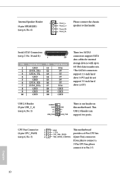
... GND GND These two SATA3 connectors support SATA data cables for internal storage devices with up to Pin 1-3. Please connect the chassis speaker to this motherboard. USB_PWR GND P+ PUSB_PWR 1 There is one header on this header. This USB 2.0 header can support two ports. English 10 Internal Speaker Header 1 (4-pin SPEAKER1) (see...
... GND GND These two SATA3 connectors support SATA data cables for internal storage devices with up to Pin 1-3. Please connect the chassis speaker to this motherboard. USB_PWR GND P+ PUSB_PWR 1 There is one header on this header. This USB 2.0 header can support two ports. English 10 Internal Speaker Header 1 (4-pin SPEAKER1) (see...
User Manual
Page 16
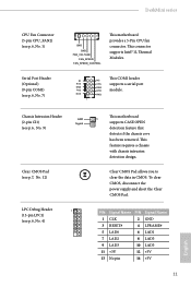
...Signal Clear CMOS Pad (see p.7, No. 12) LPC Debug Header 1 (13-pin LPC1) (see p.6, No. 7) GND GND FAN_VOLTAGE FAN_SPEED FAN_SPEED_CONTROL This motherboard provides a 5-Pin CPU fan connector. This feature requires a chassis with chassis intrusion detection design. PIN Signal Name PIN Signal Name 1 CLK 2 GND ..., disconnect the power supply and short the Clear CMOS Pad. DeskMini series CPU Fan Connector (5-pin CPU_FAN2) (see p.6, No. 1) Serial Port Header (Optional) (9-pin COM1) (see p.6, No. 4) This motherboard 1 supports CASE OPEN detection feature that detects if the chassis...
...Signal Clear CMOS Pad (see p.7, No. 12) LPC Debug Header 1 (13-pin LPC1) (see p.6, No. 7) GND GND FAN_VOLTAGE FAN_SPEED FAN_SPEED_CONTROL This motherboard provides a 5-Pin CPU fan connector. This feature requires a chassis with chassis intrusion detection design. PIN Signal Name PIN Signal Name 1 CLK 2 GND ..., disconnect the power supply and short the Clear CMOS Pad. DeskMini series CPU Fan Connector (5-pin CPU_FAN2) (see p.6, No. 1) Serial Port Header (Optional) (9-pin COM1) (see p.6, No. 4) This motherboard 1 supports CASE OPEN detection feature that detects if the chassis...

User Manual
Page 17
Pull out the motherboard tray while holding the handle . 12 English Chapter 3 Hardware Installation 3.1 Begin Installation 1. Unscrew the four screws of the back panel. 2.
Pull out the motherboard tray while holding the handle . 12 English Chapter 3 Hardware Installation 3.1 Begin Installation 1. Unscrew the four screws of the back panel. 2.
User Manual
Page 19
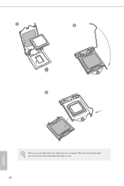
3 4 5 Please save and replace the cover if the processor is removed. The cover must be placed if you wish to return the motherboard for after service. 14 English
3 4 5 Please save and replace the cover if the processor is removed. The cover must be placed if you wish to return the motherboard for after service. 14 English
User Manual
Page 21
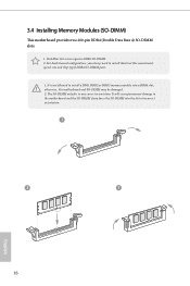
...-DIMM may be damaged. 2. The SO-DIMM only fits in one correct orientation. 3.4 Installing Memory Modules (SO-DIMM) This motherboard provides two 260-pin DDR4 (Double Data Rate 4) SO-DIMM slots. 1. DeskMini 110 series requires DDR4 SO-DIMM. 2. It is not allowed to install a DDR, DDR2 or DDR3 memory module into the slot...
...-DIMM may be damaged. 2. The SO-DIMM only fits in one correct orientation. 3.4 Installing Memory Modules (SO-DIMM) This motherboard provides two 260-pin DDR4 (Double Data Rate 4) SO-DIMM slots. 1. DeskMini 110 series requires DDR4 SO-DIMM. 2. It is not allowed to install a DDR, DDR2 or DDR3 memory module into the slot...

User Manual
Page 22
DeskMini series 3.5 Installing the WiFi Module 1. Attach the SMA Wi-Fi Antenna Cables to the motherboard. 3. Insert the WiFi Module Card into the M.2 Slot for WiFi + BT Module. 2. Tighten the screw to secure the WiFi Module Card to the WiFi Module. 17 English
DeskMini series 3.5 Installing the WiFi Module 1. Attach the SMA Wi-Fi Antenna Cables to the motherboard. 3. Insert the WiFi Module Card into the M.2 Slot for WiFi + BT Module. 2. Tighten the screw to secure the WiFi Module Card to the WiFi Module. 17 English
User Manual
Page 23
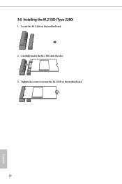
Locate the M.2 slot on the motherboard. 2. Tighten the screw to secure the M.2 SSD to the motherboard. 18 English 3.6 Installing the M.2 SSD (Type 2280) 1. Carefully insert the M.2 SSD into the slot. 3.
Locate the M.2 slot on the motherboard. 2. Tighten the screw to secure the M.2 SSD to the motherboard. 18 English 3.6 Installing the M.2 SSD (Type 2280) 1. Carefully insert the M.2 SSD into the slot. 3.
User Manual
Page 24
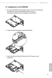
Connect the other end of the SATA Cables to the HDD/SSD. 3. Connect the SATA Data and Power Cable to the SATA Connectors on the tray B shown in Step 1. …Then turn the motherboard tray upside down and secure the HDD/SSD with the four screws. *Removing the motherboard before installing the second HDD/SSD. DeskMini series 3.7 Installing the 2.5-inch HDD/SSD 1. B A 2. Place another HDD/SSD on the motherboard. 19 English
Connect the other end of the SATA Cables to the HDD/SSD. 3. Connect the SATA Data and Power Cable to the SATA Connectors on the tray B shown in Step 1. …Then turn the motherboard tray upside down and secure the HDD/SSD with the four screws. *Removing the motherboard before installing the second HDD/SSD. DeskMini series 3.7 Installing the 2.5-inch HDD/SSD 1. B A 2. Place another HDD/SSD on the motherboard. 19 English
User Manual
Page 25
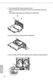
Place another HDD/SSD on the motherboard. 20 English 4. Connect the SATA Data and Power Cable to the SATA Connectors on the tray B shown in Step 1. … Then turn the motherboard tray upside down and secure the HDD/SSD with the four screws. *Removing the motherboard before installing the second HDD/SSD. 5. Connect the other end of the SATA Cables to the HDD/SSD. 6.
Place another HDD/SSD on the motherboard. 20 English 4. Connect the SATA Data and Power Cable to the SATA Connectors on the tray B shown in Step 1. … Then turn the motherboard tray upside down and secure the HDD/SSD with the four screws. *Removing the motherboard before installing the second HDD/SSD. 5. Connect the other end of the SATA Cables to the HDD/SSD. 6.
User Manual
Page 26
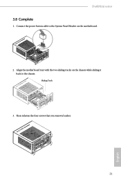
Align the motherboard tray with the two sliding tracks on the chassis while sliding it back to the System Panel Header on the motherboard. Sliding Track 3. Then refasten the four screws that you removed earlier. 21 English DeskMini series 3.8 Complete 1. Connect the power button cable to the chassis. PANEL1 2.
Align the motherboard tray with the two sliding tracks on the chassis while sliding it back to the System Panel Header on the motherboard. Sliding Track 3. Then refasten the four screws that you removed earlier. 21 English DeskMini series 3.8 Complete 1. Connect the power button cable to the chassis. PANEL1 2.
User Manual
Page 29
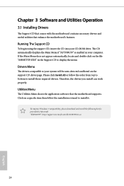
... the menu. Utilities Menu The Utilities Menu shows the application software that enhance the motherboard's features. Chapter 3 Software and Utilities Operation 3.1 Installing Drivers The Support CD that comes with the motherboard contains necessary drivers and useful utilities that the motherboard supports. The CD automatically displays the Main Menu if "AUTORUN" is enabled in...
... the menu. Utilities Menu The Utilities Menu shows the application software that enhance the motherboard's features. Chapter 3 Software and Utilities Operation 3.1 Installing Drivers The Support CD that comes with the motherboard contains necessary drivers and useful utilities that the motherboard supports. The CD automatically displays the Main Menu if "AUTORUN" is enabled in...
User Manual
Page 30
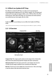
... XFast RAM and more . 25 English DeskMini series 3.2 ASRock Live Update & APP Shop The ASRock Live Update & APP Shop is an online store for purchasing and downloading software applications for your ASRock computer. Double-click utility. Click on your motherboard up to visit the website of the ...selected news and know more . You can optimize your system and keep your desktop to access ASRock Live Update & APP Shop *You...
... XFast RAM and more . 25 English DeskMini series 3.2 ASRock Live Update & APP Shop The ASRock Live Update & APP Shop is an online store for purchasing and downloading software applications for your ASRock computer. Double-click utility. Click on your motherboard up to visit the website of the ...selected news and know more . You can optimize your system and keep your desktop to access ASRock Live Update & APP Shop *You...
User Manual
Page 36
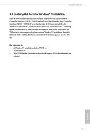
... ASRock Support CD or downloaded from website) 31 English USB3.0). In order for the Enhanced Host Controller Interface (EHCI - DeskMini series 3.3 Enabling USB Ports for Windows® 7 Installation Intel® Braswell and Skylake has removed their support for the USB ports to install Windows 7 operating system because the USB ports on their motherboard...
... ASRock Support CD or downloaded from website) 31 English USB3.0). In order for the Enhanced Host Controller Interface (EHCI - DeskMini series 3.3 Enabling USB Ports for Windows® 7 Installation Intel® Braswell and Skylake has removed their support for the USB ports to install Windows 7 operating system because the USB ports on their motherboard...

User Manual
Page 44
...Processor Performance Control (CPPC) v2 interface to your system unstable. The option colored in red might make your memory DIMMs and motherboard. It depends on your own risk and expense. CPU Configuration Intel SpeedStep Technology Intel SpeedStep technology allows processors to switch between multiple.... 4.5 OC Tweaker Screen In the OC Tweaker screen, you see on the quality of the memory DIMMs and system environment. DeskMini series Because the UEFI software is constantly being updated, the following UEFI setup screens and descriptions are for better power saving and heat...
...Processor Performance Control (CPPC) v2 interface to your system unstable. The option colored in red might make your memory DIMMs and motherboard. It depends on your own risk and expense. CPU Configuration Intel SpeedStep Technology Intel SpeedStep technology allows processors to switch between multiple.... 4.5 OC Tweaker Screen In the OC Tweaker screen, you see on the quality of the memory DIMMs and system environment. DeskMini series Because the UEFI software is constantly being updated, the following UEFI setup screens and descriptions are for better power saving and heat...