
User Manual
Page 3
Contents 1 Introduction 5 1.1 Package Contents 5 1.2 Specifications 6 1.3 Motherboard Layout (G41C-GS / G41C-S 11 1.4 I/O Panel (G41C-GS 12 1.5 I/O Panel (G41C-S 13 2 Installation 14 2.1 Screw Holes 14 2.2 Pre-installation Precautions 14 2.3 CPU Installation 15 2.4 Installation of Heatsink and CPU fan 17 2.5 Installation of Memory Modules (DIMM 18 2.6 Expansion Slots (PCI and PCI Express Slots 20 2.7 Jumpers Setup 21 2.8 Onboard Headers and Connectors...
Contents 1 Introduction 5 1.1 Package Contents 5 1.2 Specifications 6 1.3 Motherboard Layout (G41C-GS / G41C-S 11 1.4 I/O Panel (G41C-GS 12 1.5 I/O Panel (G41C-S 13 2 Installation 14 2.1 Screw Holes 14 2.2 Pre-installation Precautions 14 2.3 CPU Installation 15 2.4 Installation of Heatsink and CPU fan 17 2.5 Installation of Memory Modules (DIMM 18 2.6 Expansion Slots (PCI and PCI Express Slots 20 2.7 Jumpers Setup 21 2.8 Onboard Headers and Connectors...

User Manual
Page 6
... Technology (see CAUTION 2) - Supports Untied Overclocking Technology (see CAUTION 1) - Supports EM64T CPU - G41C-S: Realtek PCIE x1 LAN 8103EL / 8102EL, speed 10/100 Mb/s - capacity of system memory: 8GB (see CAUTION 5) - 2 x DDR2 DIMM slots - Intel® Graphics Media Accelerator X4500...667/533 non-ECC, un-buffered memory (see CAUTION 6) - capacity of system memory: 8GB (see CAUTION 5) - 1 x PCI Express x16 slot - 1 x PCI Express x1 slot - 2 x PCI slots - shared memory 1759MB (see CAUTION 4) - Supports D-Sub with max. G41C-GS: Realtek PCIE x1 Gigabit LAN ...
... Technology (see CAUTION 2) - Supports Untied Overclocking Technology (see CAUTION 1) - Supports EM64T CPU - G41C-S: Realtek PCIE x1 LAN 8103EL / 8102EL, speed 10/100 Mb/s - capacity of system memory: 8GB (see CAUTION 5) - 2 x DDR2 DIMM slots - Intel® Graphics Media Accelerator X4500...667/533 non-ECC, un-buffered memory (see CAUTION 6) - capacity of system memory: 8GB (see CAUTION 5) - 1 x PCI Express x16 slot - 1 x PCI Express x1 slot - 2 x PCI slots - shared memory 1759MB (see CAUTION 4) - Supports D-Sub with max. G41C-GS: Realtek PCIE x1 Gigabit LAN ...

User Manual
Page 8
... under Windows® 7 / VistaTM / XP. About the setting of your SATAII hard disk drive to adjust your system. The maximum shared memory size is subject to SATAII connector directly. 8 EuP Ready (EuP ready power supply is required) (see CAUTION 15) * For detailed product information..., please visit our website: http://www.asrock.com WARNING Please realize that there is no such limitation. 6. CAUTION! 1. Please read the "SATAII Hard Disk Setup Guide" on page 25 ...
... under Windows® 7 / VistaTM / XP. About the setting of your SATAII hard disk drive to adjust your system. The maximum shared memory size is subject to SATAII connector directly. 8 EuP Ready (EuP ready power supply is required) (see CAUTION 15) * For detailed product information..., please visit our website: http://www.asrock.com WARNING Please realize that there is no such limitation. 6. CAUTION! 1. Please read the "SATAII Hard Disk Setup Guide" on page 25 ...

User Manual
Page 18
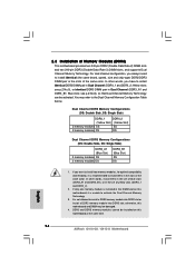
..., this motherboard and DIMM may refer to install identical (the same brand, speed, size and chip-type) DDR2/DDR3 DIMM pair in the set of Memory Modules (DIMM) This motherboard provides two 240-pin DDR2 (Double Data Rate 2) DIMM slots and two 240-pin DDR3 (Double Data Rate 3) DIMM slots,... and supports Dual Channel Memory Technology. see p.11 No.5), or identical DDR3 DIMM pair in the DIMM slot on this motherboard, it is installed in Dual Channel (DDR3_A1 and DDR3_B1...
..., this motherboard and DIMM may refer to install identical (the same brand, speed, size and chip-type) DDR2/DDR3 DIMM pair in the set of Memory Modules (DIMM) This motherboard provides two 240-pin DDR2 (Double Data Rate 2) DIMM slots and two 240-pin DDR3 (Double Data Rate 3) DIMM slots,... and supports Dual Channel Memory Technology. see p.11 No.5), or identical DDR3 DIMM pair in the DIMM slot on this motherboard, it is installed in Dual Channel (DDR3_A1 and DDR3_B1...

User Manual
Page 20
... install the add-on PCI Express VGA card to PCIE1 (PCIE x16 slot) and adjust the BIOS options "Primary Graphics Adapter" to [Onboard] and "Share Memory" to the chassis with the slot and press firmly until the card is used for the card before you install the add-on the slot...
... install the add-on PCI Express VGA card to PCIE1 (PCIE x16 slot) and adjust the BIOS options "Primary Graphics Adapter" to [Onboard] and "Share Memory" to the chassis with the slot and press firmly until the card is used for the card before you install the add-on the slot...

User Manual
Page 22
FSB1 Jumper (FSB1, 3-pin jumper, see p.11 No. 25) FSB1 Default If you adopt FSB1333-CPU and DDR3 1333 memory module on this motherboard, you need to adjust the jumper. Floppy Connector (33-pin FLOPPY1) (see p.11 No. 21) Pin1 FLOPPY1 the red-striped side ... caps over the headers and connectors will cause permanent damage of the connector. Please short pin2, pin3 for internal storage devices. Otherwise, the CPU and memory module may not work properly on this motherboard.
FSB1 Jumper (FSB1, 3-pin jumper, see p.11 No. 25) FSB1 Default If you adopt FSB1333-CPU and DDR3 1333 memory module on this motherboard, you need to adjust the jumper. Floppy Connector (33-pin FLOPPY1) (see p.11 No. 21) Pin1 FLOPPY1 the red-striped side ... caps over the headers and connectors will cause permanent damage of the connector. Please short pin2, pin3 for internal storage devices. Otherwise, the CPU and memory module may not work properly on this motherboard.

User Manual
Page 27
... security features Exit To exit the current screen or the BIOS SETUP UTILITY Use < > key or < > key to locate and load the Op- The SPI Memory on the menu bar, and then press to configure your screen. 3.1.1BIOS Menu Bar The top of the screen has a menu bar with its test...
... security features Exit To exit the current screen or the BIOS SETUP UTILITY Use < > key or < > key to locate and load the Op- The SPI Memory on the menu bar, and then press to configure your screen. 3.1.1BIOS Menu Bar The top of the screen has a menu bar with its test...

User Manual
Page 28
G41C-GS BIOS SETUP UTILITY Main OC Tweaker Advanced H/W Monitor Boot Security Exit System Overview System Time System Date [14:00:09] [Tue 12/01/2009] Use [...] Use this item to specify the system time. BIOS Version : G41C-GS P1.00 Processor Type : Intel (R) Core (TM) 2 Duo CPU E8200 @ 2.66GHz (64bit) Processor Speed : 2666MHz Microcode Update : 10676/60C Cache Size : 6144KB Total Memory DDRII1 DDRII2 DDR3_1 DDR3_2 : 2048MB Dual-Channel Memory Mode : 1024MB/333MHz DDR2_667 : 1024MB/333MHz DDR2_667 : None : None Use...
G41C-GS BIOS SETUP UTILITY Main OC Tweaker Advanced H/W Monitor Boot Security Exit System Overview System Time System Date [14:00:09] [Tue 12/01/2009] Use [...] Use this item to specify the system time. BIOS Version : G41C-GS P1.00 Processor Type : Intel (R) Core (TM) 2 Duo CPU E8200 @ 2.66GHz (64bit) Processor Speed : 2666MHz Microcode Update : 10676/60C Cache Size : 6144KB Total Memory DDRII1 DDRII2 DDR3_1 DDR3_2 : 2048MB Dual-Channel Memory Mode : 1024MB/333MHz DDR2_667 : 1024MB/333MHz DDR2_667 : None : None Use...

User Manual
Page 29
... to specify the system date. 29 System Time [Hour:Minute:Second] Use this item to specify the system time. BIOS Version : G41C-S P1.00 Processor Type : Intel (R) Core (TM) 2 Duo CPU E8200 @ 2.66GHz (64bit) Processor Speed : 2666MHz Microcode Update : ...10676/60C Cache Size : 6144KB Total Memory DDRII1 DDRII2 DDR3_1 DDR3_2 : 2048MB Dual-Channel Memory Mode : 1024MB/333MHz DDR2_667 : 1024MB/333MHz DDR2_667 : None : None Use [+] or [-] to select a field. G41C-S BIOS SETUP UTILITY Main OC Tweaker Advanced H/W Monitor Boot Security Exit ...
... to specify the system date. 29 System Time [Hour:Minute:Second] Use this item to specify the system time. BIOS Version : G41C-S P1.00 Processor Type : Intel (R) Core (TM) 2 Duo CPU E8200 @ 2.66GHz (64bit) Processor Speed : 2666MHz Microcode Update : ...10676/60C Cache Size : 6144KB Total Memory DDRII1 DDRII2 DDR3_1 DDR3_2 : 2048MB Dual-Channel Memory Mode : 1024MB/333MHz DDR2_667 : 1024MB/333MHz DDR2_667 : None : None Use [+] or [-] to select a field. G41C-S BIOS SETUP UTILITY Main OC Tweaker Advanced H/W Monitor Boot Security Exit ...

User Manual
Page 30
... DDR3_1066] or [667MHz DDR3_1333] for DDR3 or [266MHz DDR2_533], [333MHz DDR2_667] or [400MHz DDR2_800] for the CPU FSB frequency and its corresponding memory support frequency. 30 For FSB1333 CPU: FSB1 = 2-3 DRAM Voltage NB Voltage VTT Voltage GTLRef Voltage 1.96V 1.23V 1.20V 0.63Vtt [Auto] [... [333] [100] If you can set MB before apply it. DRAM Frequency If [Auto] is selected, the motherboard will detect the memory module(s) inserted and assigns appropriate frequency automatically. adjust jumper set up overclocking features. 3.3 OC Tweaker Screen In the OC Tweaker screen, you ...
... DDR3_1066] or [667MHz DDR3_1333] for DDR3 or [266MHz DDR2_533], [333MHz DDR2_667] or [400MHz DDR2_800] for the CPU FSB frequency and its corresponding memory support frequency. 30 For FSB1333 CPU: FSB1 = 2-3 DRAM Voltage NB Voltage VTT Voltage GTLRef Voltage 1.96V 1.23V 1.20V 0.63Vtt [Auto] [... [333] [100] If you can set MB before apply it. DRAM Frequency If [Auto] is selected, the motherboard will detect the memory module(s) inserted and assigns appropriate frequency automatically. adjust jumper set up overclocking features. 3.3 OC Tweaker Screen In the OC Tweaker screen, you ...

User Manual
Page 35
... CPU Frequency (MHz) PCIE Frequency (MHz) Boot Failure Guard Spread Spectrum Ratio CMOS Setting 8 Enhanced Halt State Intel (R) Virtualization tech. CPU Thermal Throttling No-Execute Memory Protection Intel (R) SpeedStep (tm) tech. Configuration options: [Auto], [Manual] and [Optimized]. In the C1 power state, the processor maintains the context of Boot Failure Guard...
... CPU Frequency (MHz) PCIE Frequency (MHz) Boot Failure Guard Spread Spectrum Ratio CMOS Setting 8 Enhanced Halt State Intel (R) Virtualization tech. CPU Thermal Throttling No-Execute Memory Protection Intel (R) SpeedStep (tm) tech. Configuration options: [Auto], [Manual] and [Optimized]. In the C1 power state, the processor maintains the context of Boot Failure Guard...

User Manual
Page 36
...issue with some power supplies. Hyper Threading Technology To enable this feature, it requires a computer system with "No Execute (NX) Memory Protection" can switch between multiple frequency and voltage points to set this function. This option will be hidden if the current CPU ...does not support No-Excute Memory Protection. Intel (R) SpeedStep(tm) tech. Intel (R) SpeedStep(tm) tech. Configuration options: [Auto], [Enabled] and [Disabled]. If you install ...
...issue with some power supplies. Hyper Threading Technology To enable this feature, it requires a computer system with "No Execute (NX) Memory Protection" can switch between multiple frequency and voltage points to set this function. This option will be hidden if the current CPU ...does not support No-Excute Memory Protection. Intel (R) SpeedStep(tm) tech. Intel (R) SpeedStep(tm) tech. Configuration options: [Auto], [Enabled] and [Disabled]. If you install ...

User Manual
Page 37
... Chipset Settings DRAM RCOMP and tRD Configuration DRAM DLL SKEW Configuration Fixed Mode Operation [Enabled] Intelligent Energy Saver Primary Graphics Adapter Shared Memory PAVP Mode DVMT Mode Select DVMT/FIXED Memory [Disabled] [PCI] [Auto] [Disabled] [DVMT Mode] [Maximum DVMT] Onboard HD Audio Front Panel OnBoard Lan [Auto] [Enabled] [Enabled] +F1 F9 F10...
... Chipset Settings DRAM RCOMP and tRD Configuration DRAM DLL SKEW Configuration Fixed Mode Operation [Enabled] Intelligent Energy Saver Primary Graphics Adapter Shared Memory PAVP Mode DVMT Mode Select DVMT/FIXED Memory [Disabled] [PCI] [Auto] [Disabled] [DVMT Mode] [Maximum DVMT] Onboard HD Audio Front Panel OnBoard Lan [Auto] [Enabled] [Enabled] +F1 F9 F10...

User Manual
Page 41
... premium content playback (Bluray disc). [Lite] mode is the encryption of compressed video buffer and is the new graphics feature in this memory with 1024MB or above. Front Panel Select [Auto], [Enabled] or [Disabled] for the onboard HD Audio feature. Intelligent Energy Saver Intelligent...as [DVMT Mode]. Configuration options: [Disabled] and [Lite]. Configuration options: [Enabled] and [Disabled]. In DVMT mode, the graphics driver allocates memory as the boot graphic adapter priority. Onboard HD Audio Select [Auto], [Enabled] or [Disabled] for the onboard HD Audio Front Panel. 41 ...
... premium content playback (Bluray disc). [Lite] mode is the encryption of compressed video buffer and is the new graphics feature in this memory with 1024MB or above. Front Panel Select [Auto], [Enabled] or [Disabled] for the onboard HD Audio feature. Intelligent Energy Saver Intelligent...as [DVMT Mode]. Configuration options: [Disabled] and [Lite]. Configuration options: [Enabled] and [Disabled]. In DVMT mode, the graphics driver allocates memory as the boot graphic adapter priority. Onboard HD Audio Select [Auto], [Enabled] or [Disabled] for the onboard HD Audio Front Panel. 41 ...

Quick Installation Guide
Page 6
... up to 2048x1536 @ 75Hz - 5.1 CH HD Audio (VIA® VT1705 Audio Codec) - G41C-GS: Realtek PCIE x1 Gigabit LAN RTL8111DL, speed 10/100/1000 Mb/s - Supports FSB1333/1066/800/533 MHz - capacity of system memory: 8GB (see CAUTION 5) - 1 x PCI Express x16 slot - 1 x PCI Express x1... PCIE x1 LAN 8103EL / 8102EL, speed 10/100 Mb/s - 1.2 Specifications Platform CPU Chipset Memory Expansion Slot Graphics Audio LAN Rear Panel I /O Panel - 1 x PS/2 Mouse Port - 1 x PS/2 Keyboard Port 6 ASRock G41C-GS / G41C-S Motherboard English LGA 775 for Intel® CoreTM 2 Extreme / CoreTM 2 Quad / CoreTM 2 ...
... up to 2048x1536 @ 75Hz - 5.1 CH HD Audio (VIA® VT1705 Audio Codec) - G41C-GS: Realtek PCIE x1 Gigabit LAN RTL8111DL, speed 10/100/1000 Mb/s - Supports FSB1333/1066/800/533 MHz - capacity of system memory: 8GB (see CAUTION 5) - 1 x PCI Express x16 slot - 1 x PCI Express x1... PCIE x1 LAN 8103EL / 8102EL, speed 10/100 Mb/s - 1.2 Specifications Platform CPU Chipset Memory Expansion Slot Graphics Audio LAN Rear Panel I /O Panel - 1 x PS/2 Mouse Port - 1 x PS/2 Keyboard Port 6 ASRock G41C-GS / G41C-S Motherboard English LGA 775 for Intel® CoreTM 2 Extreme / CoreTM 2 Quad / CoreTM 2 ...

Quick Installation Guide
Page 8
...expense. Please check Intel® website for the CPU FSB frequency and its corresponding memory support frequency. FCC, CE - Due to SATAII connector directly. 8 ASRock G41C-GS / G41C-S Motherboard English You can also connect SATA hard disk to the operating system limitation, ...the actual memory size may affect your system. The maximum shared memory size is defined by overclocking. EuP Ready (EuP ...
...expense. Please check Intel® website for the CPU FSB frequency and its corresponding memory support frequency. FCC, CE - Due to SATAII connector directly. 8 ASRock G41C-GS / G41C-S Motherboard English You can also connect SATA hard disk to the operating system limitation, ...the actual memory size may affect your system. The maximum shared memory size is defined by overclocking. EuP Ready (EuP ...
Quick Installation Guide
Page 14
... DDR2/DDR3 DIMM pair in Dual Channel (DDR3_A1 and DDR3_B1; see p.2 No.6), so that Dual Channel Memory Technology can be activated. otherwise, this motherboard at the same time. English 14 ASRock G41C-GS / G41C-S Motherboard In other words, install them in the set of blue slots (DDR3_A1 and DDR3_B1), or in... install identical DDR2 DIMM pair in the DIMM slot on this motherboard and DIMM may refer to install a DDR3 memory module into DDR2 slot or install a DDR2 memory module into DDR3 slot; You may be installed on this motherboard, it is unable to install them in the...
... DDR2/DDR3 DIMM pair in Dual Channel (DDR3_A1 and DDR3_B1; see p.2 No.6), so that Dual Channel Memory Technology can be activated. otherwise, this motherboard at the same time. English 14 ASRock G41C-GS / G41C-S Motherboard In other words, install them in the set of blue slots (DDR3_A1 and DDR3_B1), or in... install identical DDR2 DIMM pair in the DIMM slot on this motherboard and DIMM may refer to install a DDR3 memory module into DDR2 slot or install a DDR2 memory module into DDR3 slot; You may be installed on this motherboard, it is unable to install them in the...
Quick Installation Guide
Page 16
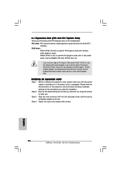
... as Gigabit LAN card, SATA2 card, etc. If you intend to use . Keep the screws for PCI Express cards with screws. 16 ASRock G41C-GS / G41C-S Motherboard English Step 4. Before installing the expansion card, please make necessary hardware settings for PCI Express cards with the slot and press firmly ...add-on PCI Express VGA card to PCIE1 (PCIE x16 slot) and adjust the BIOS options "Primary Graphics Adapter" to [Onboard] and "Share Memory" to [Auto], then the onboard VGA will be enabled, and the primary screen will be onboard VGA. Installing an expansion card Step 1. PCI...
... as Gigabit LAN card, SATA2 card, etc. If you intend to use . Keep the screws for PCI Express cards with screws. 16 ASRock G41C-GS / G41C-S Motherboard English Step 4. Before installing the expansion card, please make necessary hardware settings for PCI Express cards with the slot and press firmly ...add-on PCI Express VGA card to PCIE1 (PCIE x16 slot) and adjust the BIOS options "Primary Graphics Adapter" to [Onboard] and "Share Memory" to [Auto], then the onboard VGA will be enabled, and the primary screen will be onboard VGA. Installing an expansion card Step 1. PCI...

Quick Installation Guide
Page 18
... on this motherboard, you need to adjust the jumper. Please refer to 3.0 Gb/s data transfer rate. 18 ASRock G41C-GS / G41C-S Motherboard English Otherwise, the CPU and memory module may not work properly on this motherboard. Floppy Connector (33-pin FLOPPY1) (see p.2, No. 13) SATAII_1 SATAII_2 SATAII_3 SATAII_4 These four Serial ATAII (SATAII) ...
... on this motherboard, you need to adjust the jumper. Please refer to 3.0 Gb/s data transfer rate. 18 ASRock G41C-GS / G41C-S Motherboard English Otherwise, the CPU and memory module may not work properly on this motherboard. Floppy Connector (33-pin FLOPPY1) (see p.2, No. 13) SATAII_1 SATAII_2 SATAII_3 SATAII_4 These four Serial ATAII (SATAII) ...

Quick Installation Guide
Page 22
... motherboard features. For the detailed information about BIOS Setup, please refer to display the menus. 22 ASRock G41C-GS / G41C-S Motherboard English To begin using the Support CD, insert the CD into your computer. BIOS Information The Flash Memory on the file "ASSETUP.EXE" from the BIN folder in the Support CD to the User...
... motherboard features. For the detailed information about BIOS Setup, please refer to display the menus. 22 ASRock G41C-GS / G41C-S Motherboard English To begin using the Support CD, insert the CD into your computer. BIOS Information The Flash Memory on the file "ASSETUP.EXE" from the BIN folder in the Support CD to the User...

