User Manual
Page 3
... 3.4 Advanced Screen 35 3.4.1 CPU Configuration 36 3.4.2 Chipset Configuration 38 3.4.3 ACPI Configuration 43 3.4.4 Storage Configuration 44 3.4.5 PCIPnP Configuration 46 3.4.6 Floppy Configuration 47 3.4.7 Super IO Configuration 47 3.4.8 USB Configuration 49 3.5 Hardware Health Event Monitoring Screen 50 3.6 Boot Screen 51 3.5.1 Boot Settings Configuration 51 3
... 3.4 Advanced Screen 35 3.4.1 CPU Configuration 36 3.4.2 Chipset Configuration 38 3.4.3 ACPI Configuration 43 3.4.4 Storage Configuration 44 3.4.5 PCIPnP Configuration 46 3.4.6 Floppy Configuration 47 3.4.7 Super IO Configuration 47 3.4.8 USB Configuration 49 3.5 Hardware Health Event Monitoring Screen 50 3.6 Boot Screen 51 3.5.1 Boot Settings Configuration 51 3
User Manual
Page 7
.../Power FAN connector - 24 pin ATX power connector - 4 pin 12V power connector - AMBIOS 2.3.1 Support - Drivers, Utilities, AntiVirus Software (Trial Version), ASRock Software Suite (CyberLink DVD Suite - Front panel audio connector - 2 x USB 2.0 headers (support 4 USB 2.0 ports) - 8Mb AMI BIOS - Supports jumperfree - AMI Legal BIOS - Creative Sound Blaster X-Fi MB - Instant Boot - HD Audio Jack...
.../Power FAN connector - 24 pin ATX power connector - 4 pin 12V power connector - AMBIOS 2.3.1 Support - Drivers, Utilities, AntiVirus Software (Trial Version), ASRock Software Suite (CyberLink DVD Suite - Front panel audio connector - 2 x USB 2.0 headers (support 4 USB 2.0 ports) - 8Mb AMI BIOS - Supports jumperfree - AMI Legal BIOS - Creative Sound Blaster X-Fi MB - Instant Boot - HD Audio Jack...

User Manual
Page 9
... a few clicks without entering operating systems first like MS-DOS or Windows®. The maximum shared memory size is a revolutionary technology that the USB flash drive or hard drive must use FAT32/16/12 file system. 11. Your friends then can also connect SATA hard disk to change. ...6. Please visit our website for the operation procedures of ASRock OC Tuner. This convenient BIOS update tool allows you resume the system, please check if the CPU fan on the motherboard functions properly and...
... a few clicks without entering operating systems first like MS-DOS or Windows®. The maximum shared memory size is a revolutionary technology that the USB flash drive or hard drive must use FAT32/16/12 file system. 11. Your friends then can also connect SATA hard disk to change. ...6. Please visit our website for the operation procedures of ASRock OC Tuner. This convenient BIOS update tool allows you resume the system, please check if the CPU fan on the motherboard functions properly and...

User Manual
Page 11
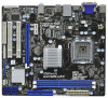
... DDR3 1333 ATXPWR1 1 USB_PWR2 CPU_FAN1 6 DDR3_B1 (64 bit, 240-pin module) DDR3_A1 (64 bit, 240-pin module) HDMI1 24.4cm (9.6 in) G41MH-LE3 32 31 30 USB 2.0 T: USB0 B: USB1 Top: RJ-45 USB 2.0 T: USB2 LAN PHY B: USB3 PWR_FAN1 Intel G41 Chipset TPM1 1 7 CHA_FAN1 8 1 Designed in Taipei ErP/EuP Ready 29 28 27 26 Top... 17 16 1 PS2_USB_PWR1 Jumper 18 Chassis Speaker Header 2 ATX 12V Connector (ATX12V1) (SPEAKER 1, White) 3 775-Pin CPU Socket 19 USB_PWR3 Jumper 4 North Bridge Controller 20 USB 2.0 Header (USB6_7, Blue) 5 2 x 240-pin DDR3 DIMM Slots 21...
... DDR3 1333 ATXPWR1 1 USB_PWR2 CPU_FAN1 6 DDR3_B1 (64 bit, 240-pin module) DDR3_A1 (64 bit, 240-pin module) HDMI1 24.4cm (9.6 in) G41MH-LE3 32 31 30 USB 2.0 T: USB0 B: USB1 Top: RJ-45 USB 2.0 T: USB2 LAN PHY B: USB3 PWR_FAN1 Intel G41 Chipset TPM1 1 7 CHA_FAN1 8 1 Designed in Taipei ErP/EuP Ready 29 28 27 26 Top... 17 16 1 PS2_USB_PWR1 Jumper 18 Chassis Speaker Header 2 ATX 12V Connector (ATX12V1) (SPEAKER 1, White) 3 775-Pin CPU Socket 19 USB_PWR3 Jumper 4 North Bridge Controller 20 USB 2.0 Header (USB6_7, Blue) 5 2 x 240-pin DDR3 DIMM Slots 21...

User Manual
Page 12
...-Streaming. 1.4 I/O Panel 1 2 3 4 5 6 11 10 9 8 7 1 PS/2 Mouse Port (Green) 2 VGA/D-Sub Port * 3 LAN RJ-45 Port 4 Line In (Light Blue) ** 5 Front Speaker (Lime) 6 Microphone (Pink) 7 USB 2.0 Ports (USB23) 8 USB 2.0 Ports (USB01) 9 HDMI Port 10 VGA/DVI-D Port 11 PS/2 Keyboard Port (Purple) * There are allowed to select "Realtek HDA Primary output" to use...
...-Streaming. 1.4 I/O Panel 1 2 3 4 5 6 11 10 9 8 7 1 PS/2 Mouse Port (Green) 2 VGA/D-Sub Port * 3 LAN RJ-45 Port 4 Line In (Light Blue) ** 5 Front Speaker (Lime) 6 Microphone (Pink) 7 USB 2.0 Ports (USB23) 8 USB 2.0 Ports (USB01) 9 HDMI Port 10 VGA/DVI-D Port 11 PS/2 Keyboard Port (Purple) * There are allowed to select "Realtek HDA Primary output" to use...

User Manual
Page 22
... on pins, the jumper is "Short". USB_PWR2 1_2 Short pin2, pin3 to enable (see p.11 No. 12) 2-pin jumper Note: CLRCMOS1 allows you select +5V_DUAL, USB devices can wake up events. Note: To select +5VSB, it requires 2 Amp and higher standby current provided by power supply. 2.8 Jumpers Setup The illustration shows...
... on pins, the jumper is "Short". USB_PWR2 1_2 Short pin2, pin3 to enable (see p.11 No. 12) 2-pin jumper Note: CLRCMOS1 allows you select +5V_DUAL, USB devices can wake up events. Note: To select +5VSB, it requires 2 Amp and higher standby current provided by power supply. 2.8 Jumpers Setup The illustration shows...

User Manual
Page 24
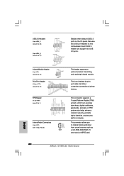
...P+6 P-6 USB_PWR USB_PWR P-5 P+5 GND DUMMY 1 GND P+4 P-4 USB_PWR IRTX +5V DUMMY 1 GND IRRX Besides three default USB 2.0 ports on the I/O panel, there are two USB 2.0 headers on this motherboard. A TPM system also helps enhance network security, protects digital identities, and ensures platform integrity. ...Each USB 2.0 header can securely store keys, digital certificates, passwords, and data. USB 2.0 Headers (9-pin USB6_7) (see p.11 No. 20) (9-pin USB4_5) (see p.11 No...
...P+6 P-6 USB_PWR USB_PWR P-5 P+5 GND DUMMY 1 GND P+4 P-4 USB_PWR IRTX +5V DUMMY 1 GND IRRX Besides three default USB 2.0 ports on the I/O panel, there are two USB 2.0 headers on this motherboard. A TPM system also helps enhance network security, protects digital identities, and ensures platform integrity. ...Each USB 2.0 header can securely store keys, digital certificates, passwords, and data. USB 2.0 Headers (9-pin USB6_7) (see p.11 No. 20) (9-pin USB4_5) (see p.11 No...
User Manual
Page 35
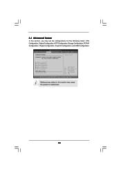
... below sections may cause system to malfunction. CPU Configuration Chipset Configuration ACPI Configuration Storage Configuration PCIPnP Configuration Floppy Configuration SuperIO Configuration USB Configuration BIOS Update Utility ASRock Instant Flash Select Screen Select Item Enter Go to malfunction. 35 3.4 Advanced Screen In this section may set the configurations ... Options for the following items: CPU Configuration, Chipset Configuration, ACPI Configuration, Storage Configuration, PCIPnP Configuration, Floppy Configuration, SuperIO Configuration, and USB Configuration.
... below sections may cause system to malfunction. CPU Configuration Chipset Configuration ACPI Configuration Storage Configuration PCIPnP Configuration Floppy Configuration SuperIO Configuration USB Configuration BIOS Update Utility ASRock Instant Flash Select Screen Select Item Enter Go to malfunction. 35 3.4 Advanced Screen In this section may set the configurations ... Options for the following items: CPU Configuration, Chipset Configuration, ACPI Configuration, Storage Configuration, PCIPnP Configuration, Floppy Configuration, SuperIO Configuration, and USB Configuration.

User Manual
Page 49
... disable USB Keyboard/Remote Power On on the system. 49 3.4.8 USB Configuration BIOS SETUP UTILITY Advanced USB Configuration USB Controller USB 2.0 Support Legacy USB Support [Enabled] [Enabled] [Enabled] USB Keyboard/Remote Power On [Disabled] USB Mouse Power On [Disabled] To enable or disable the onboard USB controllers....54 (C) Copyright 1985-2005, American Megatrends, Inc. Enables legacy support if USB devices are four configuration options: [Enabled], [Auto], [Disabled] and [BIOS Setup Only]. USB devices are allowed to use only under legacy OS and BIOS setup when [Disabled...
... disable USB Keyboard/Remote Power On on the system. 49 3.4.8 USB Configuration BIOS SETUP UTILITY Advanced USB Configuration USB Controller USB 2.0 Support Legacy USB Support [Enabled] [Enabled] [Enabled] USB Keyboard/Remote Power On [Disabled] USB Mouse Power On [Disabled] To enable or disable the onboard USB controllers....54 (C) Copyright 1985-2005, American Megatrends, Inc. Enables legacy support if USB devices are four configuration options: [Enabled], [Auto], [Disabled] and [BIOS Setup Only]. USB devices are allowed to use only under legacy OS and BIOS setup when [Disabled...

Quick Installation Guide
Page 2
...x1 Slot (PCIE1) 13 Third SATAII Connector (SATAII_3; Blue) 32 USB_PWR2 Jumper 17 System Panel Header (PANEL1, White) 33 CPU Fan Connector (CPU_FAN1) 2 ASRock G41MH-LE3 Motherboard Blue) 30 Front Panel Audio Header 14 Fourth SATAII Connector (SATAII_4; Blue) (HD_AUDIO1, White) 15 Secondary SATAII Connector (SATAII_2; Motherboard Layout English 1 ... Jumper 18 Chassis Speaker Header 2 ATX 12V Connector (ATX12V1) (SPEAKER 1, White) 3 775-Pin CPU Socket 19 USB_PWR3 Jumper 4 North Bridge Controller 20 USB 2.0 Header (USB6_7, Blue) 5 2 x 240-pin DDR3 DIMM Slots 21...
...x1 Slot (PCIE1) 13 Third SATAII Connector (SATAII_3; Blue) 32 USB_PWR2 Jumper 17 System Panel Header (PANEL1, White) 33 CPU Fan Connector (CPU_FAN1) 2 ASRock G41MH-LE3 Motherboard Blue) 30 Front Panel Audio Header 14 Fourth SATAII Connector (SATAII_4; Blue) (HD_AUDIO1, White) 15 Secondary SATAII Connector (SATAII_2; Motherboard Layout English 1 ... Jumper 18 Chassis Speaker Header 2 ATX 12V Connector (ATX12V1) (SPEAKER 1, White) 3 775-Pin CPU Socket 19 USB_PWR3 Jumper 4 North Bridge Controller 20 USB 2.0 Header (USB6_7, Blue) 5 2 x 240-pin DDR3 DIMM Slots 21...

Quick Installation Guide
Page 3
...Speaker Configuration" to the front panel audio header. Please refer to use front panel audio. Then reboot your system. 3 ASRock G41MH-LE3 Motherboard English LAN Port LED Indications Activity/Link LED SPEED LED Status Description Status Description ACT/LINK SPEED LED LED Off No...Port (Green) 2 VGA/D-Sub Port * 3 LAN RJ-45 Port 4 Line In (Light Blue) ** 5 Front Speaker (Lime) 6 Microphone (Pink) 7 USB 2.0 Ports (USB23) 8 USB 2.0 Ports (USB01) 9 HDMI Port 10 VGA/DVI-D Port 11 PS/2 Keyboard Port (Purple) * There are allowed to select "Realtek HDA Primary output" to ...
...Speaker Configuration" to the front panel audio header. Please refer to use front panel audio. Then reboot your system. 3 ASRock G41MH-LE3 Motherboard English LAN Port LED Indications Activity/Link LED SPEED LED Status Description Status Description ACT/LINK SPEED LED LED Off No...Port (Green) 2 VGA/D-Sub Port * 3 LAN RJ-45 Port 4 Line In (Light Blue) ** 5 Front Speaker (Lime) 6 Microphone (Pink) 7 USB 2.0 Ports (USB23) 8 USB 2.0 Ports (USB01) 9 HDMI Port 10 VGA/DVI-D Port 11 PS/2 Keyboard Port (Purple) * There are allowed to select "Realtek HDA Primary output" to ...

Quick Installation Guide
Page 6
... - AMI Legal BIOS - AMBIOS 2.3.1 Support - T. (Intelligent Overclocking Technology) - Supports jumperfree - Drivers, Utilities, AntiVirus Software (Trial Version), ASRock Software Suite (CyberLink DVD Suite - Trial) - Creative Sound Blaster X-Fi MB - CD in /Front Speaker/Microphone - 4 x SATAII 3.0 ...audio connector - 2 x USB 2.0 headers (support 4 USB 2.0 ports) - 8Mb AMI BIOS - HD Audio Jack: Line in header - ASRock OC Tuner (see CAUTION 11) English 6 ASRock G41MH-LE3 Motherboard ASRock OC DNA (see CAUTION 8) - OEM and Trial; ASRock Instant Flash (see CAUTION ...
... - AMI Legal BIOS - AMBIOS 2.3.1 Support - T. (Intelligent Overclocking Technology) - Supports jumperfree - Drivers, Utilities, AntiVirus Software (Trial Version), ASRock Software Suite (CyberLink DVD Suite - Trial) - Creative Sound Blaster X-Fi MB - CD in /Front Speaker/Microphone - 4 x SATAII 3.0 ...audio connector - 2 x USB 2.0 headers (support 4 USB 2.0 ports) - 8Mb AMI BIOS - HD Audio Jack: Line in header - ASRock OC Tuner (see CAUTION 11) English 6 ASRock G41MH-LE3 Motherboard ASRock OC DNA (see CAUTION 8) - OEM and Trial; ASRock Instant Flash (see CAUTION ...

Quick Installation Guide
Page 8
...Please visit our website for the latest information. 7. In other words, it back again. ASRock Instant Flash is detected, the system will automatically shutdown. OC DNA literally tells you install the PC system. 8 ASRock G41MH-LE3 Motherboard English This convenient BIOS update tool allows you to get the same OC settings as...adjust your SATAII hard disk drive to spray thermal grease between the CPU and the heatsink when you what it is subject to your USB flash drive, floppy disk or hard drive, then you can only be noticed that the OC profile can save the new BIOS ...
...Please visit our website for the latest information. 7. In other words, it back again. ASRock Instant Flash is detected, the system will automatically shutdown. OC DNA literally tells you install the PC system. 8 ASRock G41MH-LE3 Motherboard English This convenient BIOS update tool allows you to get the same OC settings as...adjust your SATAII hard disk drive to spray thermal grease between the CPU and the heatsink when you what it is subject to your USB flash drive, floppy disk or hard drive, then you can only be noticed that the OC profile can save the new BIOS ...

Quick Installation Guide
Page 18
...up the system under S3 (Suspend to short 2 pins on CLRCMOS1 for 15 seconds, use a jumper cap to RAM) state. English 18 ASRock G41MH-LE3 Motherboard When the jumper cap is placed on pins, the jumper is "Open". To clear and reset the system parameters to clear the data .... After waiting for 5 seconds. USB_PWR2 Short pin2, pin3 to enable (see p.2 No. 12) 2-pin jumper Note: CLRCMOS1 allows you select +5V_DUAL, USB devices can wake up events. The illustration shows a 3-pin jumper whose pin1 and pin2 are setup. 2.6 Jumpers Setup The illustration shows how jumpers are "...
...up the system under S3 (Suspend to short 2 pins on CLRCMOS1 for 15 seconds, use a jumper cap to RAM) state. English 18 ASRock G41MH-LE3 Motherboard When the jumper cap is placed on pins, the jumper is "Open". To clear and reset the system parameters to clear the data .... After waiting for 5 seconds. USB_PWR2 Short pin2, pin3 to enable (see p.2 No. 12) 2-pin jumper Note: CLRCMOS1 allows you select +5V_DUAL, USB devices can wake up events. The illustration shows a 3-pin jumper whose pin1 and pin2 are setup. 2.6 Jumpers Setup The illustration shows how jumpers are "...
Quick Installation Guide
Page 20
... input from sound sources such as a CD-ROM, DVD-ROM, TV tuner card, or MPEG card. 20 ASRock G41MH-LE3 Motherboard English This is an interface for print port cable that allows convenient connection of printer devices. USB 2.0 Headers (9-pin USB6_7) (see p.2 No. 20) (9-pin USB4_5) (see p.2 No. 28) CD1 This header supports an...
... input from sound sources such as a CD-ROM, DVD-ROM, TV tuner card, or MPEG card. 20 ASRock G41MH-LE3 Motherboard English This is an interface for print port cable that allows convenient connection of printer devices. USB 2.0 Headers (9-pin USB6_7) (see p.2 No. 20) (9-pin USB4_5) (see p.2 No. 28) CD1 This header supports an...


