
User Manual
Page 3
...1 1.2 Specifications 2 1.3 Motherboard Layout 6 1.4 I/O Panel 8 Chapter 2 Installation 10 2.1 Installing the CPU 11 2.2 Installing the CPU Fan and Heatsink 14 2.3 Installing Memory Modules (DIMM) 15 2.4 Expansion Slots (PCI Express Slots) 17 2.5 Jumpers Setup 18 2.6 Onboard Headers and Connectors 19 2.7 CrossFireXTM and Quad CrossFireXTM Operation Guide 23 2.7.1 Installing Two CrossFireXTM-Ready Graphics Cards 23 2.7.2 Driver Installation and Setup 25 Chapter 3 Software and Utilities Operation 26 3.1 Installing Drivers 26 3.2 A-Tuning 27 3.3 ASRock Live Update...
...1 1.2 Specifications 2 1.3 Motherboard Layout 6 1.4 I/O Panel 8 Chapter 2 Installation 10 2.1 Installing the CPU 11 2.2 Installing the CPU Fan and Heatsink 14 2.3 Installing Memory Modules (DIMM) 15 2.4 Expansion Slots (PCI Express Slots) 17 2.5 Jumpers Setup 18 2.6 Onboard Headers and Connectors 19 2.7 CrossFireXTM and Quad CrossFireXTM Operation Guide 23 2.7.1 Installing Two CrossFireXTM-Ready Graphics Cards 23 2.7.2 Driver Installation and Setup 25 Chapter 3 Software and Utilities Operation 26 3.1 Installing Drivers 26 3.2 A-Tuning 27 3.3 ASRock Live Update...

User Manual
Page 4
... 3.4 Creating Windows® 7 Installation Disk with USB 3.0 Drivers Packed 37 Chapter 4 UEFI SETUP UTILITY 41 4.1 Introduction 41 4.2 EZ Mode 42 4.3 Advanced Mode 43 4.3.1 UEFI Menu Bar 43 4.3.2 Navigation Keys 44 4.4 Main Screen 45 4.5 OC Tweaker Screen 46 4.6 Advanced Screen 54 4.6.1 CPU Configuration 55 4.6.2 Chipset Configuration 57 4.6.3 Storage Configuration 59 4.6.4 ACPI Configuration 60 4.6.5 USB Configuration 62 4.6.6 Trusted Computing 63 4.7 Tools 64 4.8 Hardware Health Event Monitoring Screen 67 4.9 Security Screen 69 4.10 Boot Screen 70...
... 3.4 Creating Windows® 7 Installation Disk with USB 3.0 Drivers Packed 37 Chapter 4 UEFI SETUP UTILITY 41 4.1 Introduction 41 4.2 EZ Mode 42 4.3 Advanced Mode 43 4.3.1 UEFI Menu Bar 43 4.3.2 Navigation Keys 44 4.4 Main Screen 45 4.5 OC Tweaker Screen 46 4.6 Advanced Screen 54 4.6.1 CPU Configuration 55 4.6.2 Chipset Configuration 57 4.6.3 Storage Configuration 59 4.6.4 ACPI Configuration 60 4.6.5 USB Configuration 62 4.6.6 Trusted Computing 63 4.7 Tools 64 4.8 Hardware Health Event Monitoring Screen 67 4.9 Security Screen 69 4.10 Boot Screen 70...
User Manual
Page 5
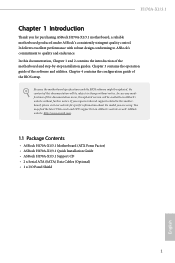
... 4 contains the configuration guide of the software and utilities. You may find the latest VGA cards and CPU support list on ASRock's website without notice. ASRock website http://www.asrock.com. 1.1 Package Contents • ASRock H170A-X1/3.1 Motherboard (ATX Form Factor) • ASRock H170A-X1/3.1 Quick Installation Guide • ASRock H170A-X1/3.1 Support CD • 2 x Serial ATA (SATA) Data Cables (Optional) • 1 x I/O Panel Shield 1 English H170A-X1/3.1 Chapter 1 Introduction Thank you for specific information about the model you require technical support related to this...
... 4 contains the configuration guide of the software and utilities. You may find the latest VGA cards and CPU support list on ASRock's website without notice. ASRock website http://www.asrock.com. 1.1 Package Contents • ASRock H170A-X1/3.1 Motherboard (ATX Form Factor) • ASRock H170A-X1/3.1 Quick Installation Guide • ASRock H170A-X1/3.1 Support CD • 2 x Serial ATA (SATA) Data Cables (Optional) • 1 x I/O Panel Shield 1 English H170A-X1/3.1 Chapter 1 Introduction Thank you for specific information about the model you require technical support related to this...

User Manual
Page 6
capacity of system memory: 64GB • Supports Intel® Extreme Memory Profile (XMP) 2.0 • 15μ Gold Contact in Visuals : Intel® Quick Sync Video with processors which are GPU integrated. • Supports Intel® HD Graphics Built-in DIMM Slots Expansion Slot • 2 x PCI Express 3.0 x16 Slots (PCIE2: x16 mode; ECC mode) • Max. PCIE4: x4 mode)* * Supports NVMe SSD as boot disks • 3 x PCI Express 3.0 x1 Slots (Flexible PCIe) • Supports AMD Quad CrossFireXTM and...
capacity of system memory: 64GB • Supports Intel® Extreme Memory Profile (XMP) 2.0 • 15μ Gold Contact in Visuals : Intel® Quick Sync Video with processors which are GPU integrated. • Supports Intel® HD Graphics Built-in DIMM Slots Expansion Slot • 2 x PCI Express 3.0 x16 Slots (PCIE2: x16 mode; ECC mode) • Max. PCIE4: x4 mode)* * Supports NVMe SSD as boot disks • 3 x PCI Express 3.0 x1 Slots (Flexible PCIe) • Supports AMD Quad CrossFireXTM and...
User Manual
Page 7
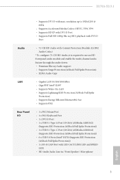
.../2 Mouse Port • 1 x PS/2 Keyboard Port • 1 x DVI-D Port • 1 x USB 3.1 Type-A Port (10 Gb/s) (ASMedia ASM1142) (Supports ESD Protection (ASRock Full Spike Protection)) • 1 x USB 3.1 Type-C Port (10 Gb/s) (ASMedia ASM1142) (Supports ESD Protection (ASRock Full Spike Protection)) • 6 x USB 3.0 Ports (Intel® H170) (Supports ESD Protection (ASRock Full Spike Protection)) • 1 x RJ-45 LAN Port with max. H170A-X1/3.1 • Supports DVI-D with LED (ACT/LINK LED and SPEED LED) • HD Audio Jacks: Line in / Front Speaker...
.../2 Mouse Port • 1 x PS/2 Keyboard Port • 1 x DVI-D Port • 1 x USB 3.1 Type-A Port (10 Gb/s) (ASMedia ASM1142) (Supports ESD Protection (ASRock Full Spike Protection)) • 1 x USB 3.1 Type-C Port (10 Gb/s) (ASMedia ASM1142) (Supports ESD Protection (ASRock Full Spike Protection)) • 6 x USB 3.0 Ports (Intel® H170) (Supports ESD Protection (ASRock Full Spike Protection)) • 1 x RJ-45 LAN Port with max. H170A-X1/3.1 • Supports DVI-D with LED (ACT/LINK LED and SPEED LED) • HD Audio Jacks: Line in / Front Speaker...

User Manual
Page 8
...Intel Smart Response Technology), NCQ, AHCI and Hot Plug Connector • 1 x TPM Header • 1 x Power LED and Speaker Header • 1 x CPU Fan Connector (4-pin) • 2 x Chassis Fan Connectors (4-pin) • 1 x 24 pin ATX Power Connector • 1 x 8 pin 12V Power Connector • 1 x Front Panel Audio Connector • 2 x USB 2.0 Headers (Support 4 USB 2.0 ports) (Supports ESD Protection (ASRock Full Spike Protection)) • 1 x USB 3.0 Header (Supports 2 USB 3.0 ports) (Supports ESD Protection (ASRock Full Spike Protection)) BIOS Feature • AMI UEFI Legal BIOS with...
...Intel Smart Response Technology), NCQ, AHCI and Hot Plug Connector • 1 x TPM Header • 1 x Power LED and Speaker Header • 1 x CPU Fan Connector (4-pin) • 2 x Chassis Fan Connectors (4-pin) • 1 x 24 pin ATX Power Connector • 1 x 8 pin 12V Power Connector • 1 x Front Panel Audio Connector • 2 x USB 2.0 Headers (Support 4 USB 2.0 ports) (Supports ESD Protection (ASRock Full Spike Protection)) • 1 x USB 3.0 Header (Supports 2 USB 3.0 ports) (Supports ESD Protection (ASRock Full Spike Protection)) BIOS Feature • AMI UEFI Legal BIOS with...

User Manual
Page 11
... 2 x 288-pin DDR4 DIMM Slots (DDR4_A2, DDR4_B2) 5 ATX Power Connector (ATXPWR1) 6 USB 3.0 Header (USB3_4_5) 7 Chassis Fan Connector (CHA_FAN1) 8 Clear CMOS Jumper (CLRMOS1) 9 SATA3 Connector (SATA3_2) 10 Chassis Fan Connector (CHA_FAN2) 11 Power LED and Speaker Header (SPK_PLED1) 12 SATA3 Connector (SATA3_0) 13 System Panel Header (PANEL1) 14 SATA3 Connector (SATA3_1) 15 SATA3 Connector (SATA3_3) 16 SATA3 Connector (SATA3_5) 17 SATA3 Connector (SATA3_4) 18 USB 2.0 Header (USB2_3) 19 USB 2.0 Header (USB4_5) 20 TPM Header (TPMS1) 21 Front Panel Audio Header (HD_AUDIO1) H170A-X1/3.1 English 7
... 2 x 288-pin DDR4 DIMM Slots (DDR4_A2, DDR4_B2) 5 ATX Power Connector (ATXPWR1) 6 USB 3.0 Header (USB3_4_5) 7 Chassis Fan Connector (CHA_FAN1) 8 Clear CMOS Jumper (CLRMOS1) 9 SATA3 Connector (SATA3_2) 10 Chassis Fan Connector (CHA_FAN2) 11 Power LED and Speaker Header (SPK_PLED1) 12 SATA3 Connector (SATA3_0) 13 System Panel Header (PANEL1) 14 SATA3 Connector (SATA3_1) 15 SATA3 Connector (SATA3_3) 16 SATA3 Connector (SATA3_5) 17 SATA3 Connector (SATA3_4) 18 USB 2.0 Header (USB2_3) 19 USB 2.0 Header (USB4_5) 20 TPM Header (TPMS1) 21 Front Panel Audio Header (HD_AUDIO1) H170A-X1/3.1 English 7

User Manual
Page 19
... memory module installed. 3. It is unable to install identical (the same brand, speed, size and chip-type) DDR4 DIMM pairs. 2. It will cause permanent damage to install a DDR, DDR2 or DDR3 memory module into the slot at incorrect orientation. For dual channel configuration, you force the DIMM into a DDR4 slot; H170A-X1/3.1 2.3 Installing Memory Modules (DIMM) This motherboard provides four 288-pin DDR4 (Double Data Rate 4) DIMM slots, and supports Dual Channel Memory Technology. 1. otherwise, this motherboard...
... memory module installed. 3. It is unable to install identical (the same brand, speed, size and chip-type) DDR4 DIMM pairs. 2. It will cause permanent damage to install a DDR, DDR2 or DDR3 memory module into the slot at incorrect orientation. For dual channel configuration, you force the DIMM into a DDR4 slot; H170A-X1/3.1 2.3 Installing Memory Modules (DIMM) This motherboard provides four 288-pin DDR4 (Double Data Rate 4) DIMM slots, and supports Dual Channel Memory Technology. 1. otherwise, this motherboard...

User Manual
Page 21
... 3.0 x16 slot) is used for PCI Express x16 lane width graphics cards. PCIe Slot Configurations Single Graphics Card Two Graphics Cards in CrossFireXTM Mode PCIE2 x16 x16 PCIE4 N/A x4 For a better thermal environment, please connect a chassis fan to the motherboard's chassis fan connector (CHA_FAN1 or CHA_FAN2) when using multiple graphics cards. PCIE3 (PCIe 3.0 x1 slot) is used for PCI Express x4 lane width graphics cards. PCIE4 (PCIe 3.0 x16 slot) is used for PCI Express x1 lane width cards. PCIE5 (PCIe 3.0 x1 slot) is used for the card before you start the installation...
... 3.0 x16 slot) is used for PCI Express x16 lane width graphics cards. PCIe Slot Configurations Single Graphics Card Two Graphics Cards in CrossFireXTM Mode PCIE2 x16 x16 PCIE4 N/A x4 For a better thermal environment, please connect a chassis fan to the motherboard's chassis fan connector (CHA_FAN1 or CHA_FAN2) when using multiple graphics cards. PCIE3 (PCIe 3.0 x1 slot) is used for PCI Express x4 lane width graphics cards. PCIE4 (PCIe 3.0 x16 slot) is used for PCI Express x1 lane width cards. PCIE5 (PCIe 3.0 x1 slot) is used for the card before you start the installation...

User Manual
Page 23
... configure the way to the power switch on the chassis to this header, make sure the wire assignments and the pin assignments are NOT jumpers. H170A-X1/3.1 2.6 Onboard Headers and Connectors Onboard headers and connectors are matched correctly. RESET (Reset Switch): Connect to the hard drive activity LED on the chassis front panel. The LED keeps blinking when the system is reading or writing data. When connecting your system using the power switch. Placing jumper caps over these headers and connectors. HDLED (Hard Drive Activity LED): Connect...
... configure the way to the power switch on the chassis to this header, make sure the wire assignments and the pin assignments are NOT jumpers. H170A-X1/3.1 2.6 Onboard Headers and Connectors Onboard headers and connectors are matched correctly. RESET (Reset Switch): Connect to the hard drive activity LED on the chassis front panel. The LED keeps blinking when the system is reading or writing data. When connecting your system using the power switch. Placing jumper caps over these headers and connectors. HDLED (Hard Drive Activity LED): Connect...
User Manual
Page 25
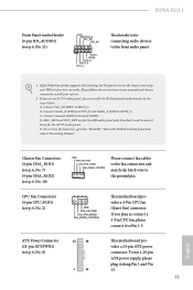
... p.6, No. 8) 12 24 1 13 This motherboard provides a 24-pin ATX power connector. H170A-X1/3.1 Front Panel Audio Header (9-pin HD_AUDIO1) (see p.6, No. 2) 4 3 21 GND FAN_VOLTAGE CPU_FAN_SPEED FAN_SPEED_CONTROL This motherboard provides a 4-Pin CPU fan (Quiet Fan) connector. C. If you use a 20-pin ATX power supply, please plug it to the front panel audio header by the steps below: A. High Definition Audio supports Jack Sensing, but the panel wire on the chassis must support HDA to the front audio panel. 1. B. CPU Fan Connectors (4-pin CPU_FAN1) (see p.6, No. 21) GND PRESENCE...
... p.6, No. 8) 12 24 1 13 This motherboard provides a 24-pin ATX power connector. H170A-X1/3.1 Front Panel Audio Header (9-pin HD_AUDIO1) (see p.6, No. 2) 4 3 21 GND FAN_VOLTAGE CPU_FAN_SPEED FAN_SPEED_CONTROL This motherboard provides a 4-Pin CPU fan (Quiet Fan) connector. C. If you use a 20-pin ATX power supply, please plug it to the front panel audio header by the steps below: A. High Definition Audio supports Jack Sensing, but the panel wire on the chassis must support HDA to the front audio panel. 1. B. CPU Fan Connectors (4-pin CPU_FAN1) (see p.6, No. 21) GND PRESENCE...
User Manual
Page 27
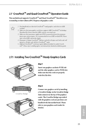
... identical PCI Express x16 graphics cards. 1. Please refer to AMD graphics card manuals for detailed installation guide. 2.7.1 Installing Two CrossFireXTM-Ready Graphics Cards Step 1 Insert one graphics card into PCIE2 slot and the other graphics card to enable CrossFireXTM. If you pair a 12-pipe CrossFireXTM Edition card with this motherboard. Make sure that your system requires. CrossFire Bridge Step 2 Connect two graphics cards by installing a CrossFire Bridge on the CrossFire Bridge Interconnects on the slots. H170A-X1/3.1 2.7 CrossFireXTM...
... identical PCI Express x16 graphics cards. 1. Please refer to AMD graphics card manuals for detailed installation guide. 2.7.1 Installing Two CrossFireXTM-Ready Graphics Cards Step 1 Insert one graphics card into PCIE2 slot and the other graphics card to enable CrossFireXTM. If you pair a 12-pipe CrossFireXTM Edition card with this motherboard. Make sure that your system requires. CrossFire Bridge Step 2 Connect two graphics cards by installing a CrossFire Bridge on the CrossFire Bridge Interconnects on the slots. H170A-X1/3.1 2.7 CrossFireXTM...

User Manual
Page 29
... AMD's website for AMD driver updates. Step 2 Remove the AMD drivers if you have any previously installed Catalyst drivers prior to your computer and boot into OS. Step 3 Install the required drivers and CATALYST Control Center then restart your system. The Catalyst Uninstaller is an optional download. We recommend using this utility to uninstall any VGA drivers installed in the Windows® system tray. Then select Enable AMD CrossFireX and click Apply. AMD Catalyst Control...
... AMD's website for AMD driver updates. Step 2 Remove the AMD drivers if you have any previously installed Catalyst drivers prior to your computer and boot into OS. Step 3 Install the required drivers and CATALYST Control Center then restart your system. The Catalyst Uninstaller is an optional download. We recommend using this utility to uninstall any VGA drivers installed in the Windows® system tray. Then select Enable AMD CrossFireX and click Apply. AMD Catalyst Control...
User Manual
Page 30
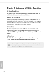
... comes with the motherboard contains necessary drivers and useful utilities that the motherboard supports. If the Main Menu does not appear automatically, locate and double click on a specific item then follow the order from top to bottom to install it. Click on the file "ASRSETUP.EXE" in your computer. The CD automatically displays the Main Menu if "AUTORUN" is enabled in the Support CD to your CD-ROM drive.
... comes with the motherboard contains necessary drivers and useful utilities that the motherboard supports. If the Main Menu does not appear automatically, locate and double click on a specific item then follow the order from top to bottom to install it. Click on the file "ASRSETUP.EXE" in your computer. The CD automatically displays the Main Menu if "AUTORUN" is enabled in the Support CD to your CD-ROM drive.

User Manual
Page 41
... the ASRock Support CD) • Windows® PC Instructions Step 1 Create a new folder under the "asrock" folder. Requirements • A program that can create and modify ISO files, such as UltraISO • Windows® 7 installation disk • USB 3.0 drivers (included in your CD drive. Step 4 Copy "boot.wim" and "install.wim" files from the "Sources" folder in your CD drive. Step 6 Go to function properly. H170A-X1/3.1 3.4 Creating Windows® 7 Installation Disk...
... the ASRock Support CD) • Windows® PC Instructions Step 1 Create a new folder under the "asrock" folder. Requirements • A program that can create and modify ISO files, such as UltraISO • Windows® 7 installation disk • USB 3.0 drivers (included in your CD drive. Step 4 Copy "boot.wim" and "install.wim" files from the "Sources" folder in your CD drive. Step 6 Go to function properly. H170A-X1/3.1 3.4 Creating Windows® 7 Installation Disk...

User Manual
Page 62
... Keyboard LEDs when the system enters into Standby/Hibernation mode. 58 English PCH DMI ASPM Support This option enables/disables the ASPM support for power saving when the computer is installed. Set to Auto to boot up . DMI ASPM Support This option enables/disables the control of ASPM on . If [Power Off] is installed. IGPU Multi-Monitor Select disable to disable the integrated graphics when an external graphics card is selected, the power will start to enable onboard HD audio and automatically disable...
... Keyboard LEDs when the system enters into Standby/Hibernation mode. 58 English PCH DMI ASPM Support This option enables/disables the ASPM support for power saving when the computer is installed. Set to Auto to boot up . DMI ASPM Support This option enables/disables the control of ASPM on . If [Power Off] is installed. IGPU Multi-Monitor Select disable to disable the integrated graphics when an external graphics card is selected, the power will start to enable onboard HD audio and automatically disable...
User Manual
Page 68
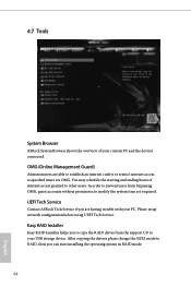
... Service if you are able to RAID, then you to copy the RAID driver from bypassing OMG, guest accounts without permission to your PC. After copying the drivers please change the SATA mode to establish an internet curfew or restrict internet access at specified times via OMG. Please setup network configuration before using UEFI Tech Service. OMG (Online Management Guard) Administrators are having trouble with your USB storage device...
... Service if you are able to RAID, then you to copy the RAID driver from bypassing OMG, guest accounts without permission to your PC. After copying the drivers please change the SATA mode to establish an internet curfew or restrict internet access at specified times via OMG. Please setup network configuration before using UEFI Tech Service. OMG (Online Management Guard) Administrators are having trouble with your USB storage device...
User Manual
Page 69
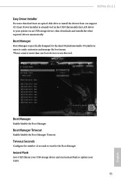
... UEFI files in the UEFI that installs the LAN driver to your UEFI. 65 English Timeout Seconds Configure the number of seconds to wait for the dual OS platform/multi-OS platform users to easily customize and manage the boot menu. *Please connect more than one boot devices to use this tool. H170A-X1/3.1 Easy Driver Installer For users that don't have an optical disk drive to install the drivers from our support CD, Easy Driver Installer is specifically...
... UEFI files in the UEFI that installs the LAN driver to your UEFI. 65 English Timeout Seconds Configure the number of seconds to wait for the dual OS platform/multi-OS platform users to easily customize and manage the boot menu. *Please connect more than one boot devices to use this tool. H170A-X1/3.1 Easy Driver Installer For users that don't have an optical disk drive to install the drivers from our support CD, Easy Driver Installer is specifically...
User Manual
Page 70
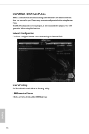
Internet Setting Enable or disable sound effects in your USB pen drive before using Internet Flash. *For BIOS backup and recovery purpose, it is recommended to download the UEFI firmware. 66 English DHCP (Auto IP), Auto ASRock Internet Flash downloads and updates the latest UEFI firmware version from our servers for Internet Flash. Network Configuration Use this function. Internet Flash - UEFI Download Server Select a server to plug in the setup utility. Please setup network configuration before using this to configure internet connection settings for you.
Internet Setting Enable or disable sound effects in your USB pen drive before using Internet Flash. *For BIOS backup and recovery purpose, it is recommended to download the UEFI firmware. 66 English DHCP (Auto IP), Auto ASRock Internet Flash downloads and updates the latest UEFI firmware version from our servers for Internet Flash. Network Configuration Use this function. Internet Flash - UEFI Download Server Select a server to plug in the setup utility. Please setup network configuration before using this to configure internet connection settings for you.
User Manual
Page 73
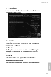
... user password. You may set or change the supervisor/user password for Windows 8.1 Secure Boot. Leave it blank and press enter to change the password for the administrator account. User Password Set or change the settings in ME. Disable this item to use discrete TPM Module. 69 English Secure Boot Use this option to enable or disable support for the system. Intel(R) Platform Trust Technology Enable/disable Intel PTT in the UEFI Setup Utility. Only the administrator has authority to remove...
... user password. You may set or change the supervisor/user password for Windows 8.1 Secure Boot. Leave it blank and press enter to change the password for the administrator account. User Password Set or change the settings in ME. Disable this item to use discrete TPM Module. 69 English Secure Boot Use this option to enable or disable support for the system. Intel(R) Platform Trust Technology Enable/disable Intel PTT in the UEFI Setup Utility. Only the administrator has authority to remove...


