
User Manual
Page 6
...1.2 Specifications 2 1.3 Motherboard Layout 6 1.4 I/O Panel 9 Chapter 2 Installation 11 2.1 Installing the CPU 12 2.2 Installing the CPU Fan and Heatsink 15 2.3 Installing Memory Modules (DIMM) 16 2.4 Expansion Slots (PCIe Slots) 18 2.5 Jumpers Setup 19 2.6 Onboard Headers and Connectors 20 2.7 M.2_SSD (NGFF) Module Installation Guide (M2_2) 24 Chapter 3 Software and Utilities Operation 27 3.1 Installing Drivers 27 3.2 ASRock Motherboard Utility (A-Tuning) 28 3.2.1 Installing ASRock Motherboard Utility (A-Tuning) 28 3.2.2 Using ASRock Motherboard Utility (A-Tuning...
...1.2 Specifications 2 1.3 Motherboard Layout 6 1.4 I/O Panel 9 Chapter 2 Installation 11 2.1 Installing the CPU 12 2.2 Installing the CPU Fan and Heatsink 15 2.3 Installing Memory Modules (DIMM) 16 2.4 Expansion Slots (PCIe Slots) 18 2.5 Jumpers Setup 19 2.6 Onboard Headers and Connectors 20 2.7 M.2_SSD (NGFF) Module Installation Guide (M2_2) 24 Chapter 3 Software and Utilities Operation 27 3.1 Installing Drivers 27 3.2 ASRock Motherboard Utility (A-Tuning) 28 3.2.1 Installing ASRock Motherboard Utility (A-Tuning) 28 3.2.2 Using ASRock Motherboard Utility (A-Tuning...
User Manual
Page 8
... about the model you for M.2 Socket (Optional) • 1 x I/O Panel Shield 1 English Because the motherboard specifications and the BIOS software might be updated, the content of this documentation occur, the updated version will be available on ASRock's website as well. You may find the latest VGA cards and CPU support list on ASRock's website without notice. It delivers excellent performance with robust design conforming to ASRock's commitment to change without further...
... about the model you for M.2 Socket (Optional) • 1 x I/O Panel Shield 1 English Because the motherboard specifications and the BIOS software might be updated, the content of this documentation occur, the updated version will be available on ASRock's website as well. You may find the latest VGA cards and CPU support list on ASRock's website without notice. It delivers excellent performance with robust design conforming to ASRock's commitment to change without further...
User Manual
Page 9
... Memory • Dual Channel DDR4 Memory Technology • 2 x DDR4 DIMM Slots • Supports DDR4 non-ECC, un-buffered memory up to Memory Support List on ASRock's website for more information. (http://www.asrock.com/) • Supports ECC UDIMM memory modules (operate in Visuals and the VGA outputs can be supported only with processors which are GPU integrated. • Intel® Xe Graphics Architecture (Gen 12) H610M-HDV/M.2 R2.0: • Three graphics output options...
... Memory • Dual Channel DDR4 Memory Technology • 2 x DDR4 DIMM Slots • Supports DDR4 non-ECC, un-buffered memory up to Memory Support List on ASRock's website for more information. (http://www.asrock.com/) • Supports ECC UDIMM memory modules (operate in Visuals and the VGA outputs can be supported only with processors which are GPU integrated. • Intel® Xe Graphics Architecture (Gen 12) H610M-HDV/M.2 R2.0: • Three graphics output options...
User Manual
Page 10
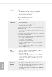
.../Keyboard Port • 2 x USB 3.2 Gen1 Ports (Supports ESD Protection) • 4 x USB 2.0 Ports (Supports ESD Protection) • 1 x RJ-45 LAN Port with max. resolution up to 1920x1200 @ 60Hz • Supports HDCP 2.3 with HDMI 2.1 TMDS Compatible and DisplayPort 1.4 Ports H610M-HVS/M.2 R2.0: • Dual graphics output: support HDMI and D-Sub ports by independent display controllers • Supports HDMI 2.1 TMDS Compatible with LED (ACT/LINK LED and SPEED LED) • HD Audio Jacks: Line in / Front Speaker / Microphone H610M-HDV/M.2 R2.0: • 1 x D-Sub Port • 1 x HDMI Port...
.../Keyboard Port • 2 x USB 3.2 Gen1 Ports (Supports ESD Protection) • 4 x USB 2.0 Ports (Supports ESD Protection) • 1 x RJ-45 LAN Port with max. resolution up to 1920x1200 @ 60Hz • Supports HDCP 2.3 with HDMI 2.1 TMDS Compatible and DisplayPort 1.4 Ports H610M-HVS/M.2 R2.0: • Dual graphics output: support HDMI and D-Sub ports by independent display controllers • Supports HDMI 2.1 TMDS Compatible with LED (ACT/LINK LED and SPEED LED) • HD Audio Jacks: Line in / Front Speaker / Microphone H610M-HDV/M.2 R2.0: • 1 x D-Sub Port • 1 x HDMI Port...
User Manual
Page 11
...x 8 pin 12V Power Connector • 1 x Front Panel Audio Connector • 1 x USB 2.0 Header (Supports 2 USB 2.0 ports) (Supports ESD Protection) • 1 x USB 3.2 Gen1 Header (Supports 2 USB 3.2 Gen1 ports) (Supports ESD Protection) BIOS Feature • AMI UEFI Legal BIOS with multilingual GUI support • ACPI 6.0 Compliant wake up events • SMBIOS 2.7 Support • CPU Core/Cache, CPU Core/Cache Load-Line, CPU GT, CPU GT Load-Line, DRAM, +0.82V PCH, +1.05V PCH, VCCIN AUX, +1.8V PROC, +1.05V PROC Voltage Multiadjustment Hardware Monitor • Fan Tachometer: CPU, Chassis...
...x 8 pin 12V Power Connector • 1 x Front Panel Audio Connector • 1 x USB 2.0 Header (Supports 2 USB 2.0 ports) (Supports ESD Protection) • 1 x USB 3.2 Gen1 Header (Supports 2 USB 3.2 Gen1 ports) (Supports ESD Protection) BIOS Feature • AMI UEFI Legal BIOS with multilingual GUI support • ACPI 6.0 Compliant wake up events • SMBIOS 2.7 Support • CPU Core/Cache, CPU Core/Cache Load-Line, CPU GT, CPU GT Load-Line, DRAM, +0.82V PCH, +1.05V PCH, VCCIN AUX, +1.8V PROC, +1.05V PROC Voltage Multiadjustment Hardware Monitor • Fan Tachometer: CPU, Chassis...
User Manual
Page 12
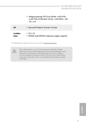
... damage to the components and devices of your own risk and expense. H610M-HDV/M.2 R2.0 H610M-HVS/M.2 R2.0 OS Certifications • Voltage monitoring: CPU Vcore, DRAM, +0.82V PCH, +1.05V PCH, VCCIN AUX, VCCSA, +1.05V PROC, +12V, +5V, +3.3V • Microsoft® Windows® 10 64-bit / 11 64-bit • FCC, CE • ErP/EuP ready (ErP/EuP ready power supply is required) * For detailed...
... damage to the components and devices of your own risk and expense. H610M-HDV/M.2 R2.0 H610M-HVS/M.2 R2.0 OS Certifications • Voltage monitoring: CPU Vcore, DRAM, +0.82V PCH, +1.05V PCH, VCCIN AUX, VCCSA, +1.05V PROC, +12V, +5V, +3.3V • Microsoft® Windows® 10 64-bit / 11 64-bit • FCC, CE • ErP/EuP ready (ErP/EuP ready power supply is required) * For detailed...
User Manual
Page 15
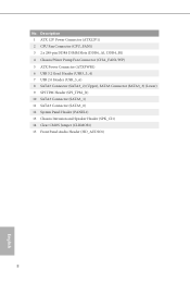
No. Description 1 ATX 12V Power Connector (ATX12V1) 2 CPU Fan Connector (CPU_FAN1) 3 2 x 288-pin DDR4 DIMM Slots (DDR4_A1, DDR4_B1) 4 Chassis/Water Pump Fan Connector (CHA_FAN1/WP) 5 ATX Power Connector (ATXPWR1) 6 USB 3.2 Gen1 Header (USB3_3_4) 7 USB 2.0 Header (USB_5_6) 8 SATA3 Connector (SATA3_2) (Upper), SATA3 Connector (SATA3_3) (Lower) 9 SPI TPM Header (SPI_TPM_J1) 10 SATA3 Connector (SATA3_1) 11 SATA3 Connector (SATA3_0) 12 System Panel Header (PANEL1) 13 Chassis Intrusion and Speaker Header (SPK_CI1) 14 Clear CMOS Jumper (CLRMOS1) 15 Front Panel Audio Header (HD_AUDIO1) 8 English
No. Description 1 ATX 12V Power Connector (ATX12V1) 2 CPU Fan Connector (CPU_FAN1) 3 2 x 288-pin DDR4 DIMM Slots (DDR4_A1, DDR4_B1) 4 Chassis/Water Pump Fan Connector (CHA_FAN1/WP) 5 ATX Power Connector (ATXPWR1) 6 USB 3.2 Gen1 Header (USB3_3_4) 7 USB 2.0 Header (USB_5_6) 8 SATA3 Connector (SATA3_2) (Upper), SATA3 Connector (SATA3_3) (Lower) 9 SPI TPM Header (SPI_TPM_J1) 10 SATA3 Connector (SATA3_1) 11 SATA3 Connector (SATA3_0) 12 System Panel Header (PANEL1) 13 Chassis Intrusion and Speaker Header (SPK_CI1) 14 Clear CMOS Jumper (CLRMOS1) 15 Front Panel Audio Header (HD_AUDIO1) 8 English
User Manual
Page 18
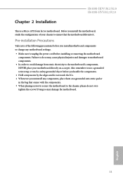
... not overtighten the screws! Before you install motherboard components or change any components, place them on a carpet. H610M-HDV/M.2 R2.0 H610M-HVS/M.2 R2.0 Chapter 2 Installation This is a Micro ATX form factor motherboard. Pre-installation Precautions Take note of your motherboard directly on a grounded anti-static pad or in the bag that the motherboard fits into it. Failure to the chassis, please do so may damage the...
... not overtighten the screws! Before you install motherboard components or change any components, place them on a carpet. H610M-HDV/M.2 R2.0 H610M-HVS/M.2 R2.0 Chapter 2 Installation This is a Micro ATX form factor motherboard. Pre-installation Precautions Take note of your motherboard directly on a grounded anti-static pad or in the bag that the motherboard fits into it. Failure to the chassis, please do so may damage the...
User Manual
Page 26
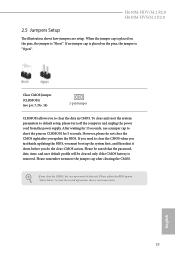
H610M-HDV/M.2 R2.0 H610M-HVS/M.2 R2.0 2.5 Jumpers Setup The illustration shows how jumpers are setup. Please remember toremove the jumper cap after you to clear the record of previous chassis intrusion status. Please adjust the BIOS option "Clear Status" to clear the data in CMOS. Clear CMOS Jumper (CLRMOS1) (see p.6, 7, No. 14) 2-pin Jumper CLRMOS1 allows you update the BIOS. If you need to clear the CMOS when you just finish updating the BIOS, you must boot up the system...
H610M-HDV/M.2 R2.0 H610M-HVS/M.2 R2.0 2.5 Jumpers Setup The illustration shows how jumpers are setup. Please remember toremove the jumper cap after you to clear the record of previous chassis intrusion status. Please adjust the BIOS option "Clear Status" to clear the data in CMOS. Clear CMOS Jumper (CLRMOS1) (see p.6, 7, No. 14) 2-pin Jumper CLRMOS1 allows you update the BIOS. If you need to clear the CMOS when you just finish updating the BIOS, you must boot up the system...
User Manual
Page 28
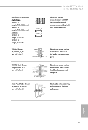
... support two ports. USB 2.0 Header (9-pin USB_5_6) (see p.6, 7, No. 7) DUMMY GND +B -B USB_PWR GND +A -A USB_PWR 1 There is for internal storage devices with up to the front audio panel. This USB 2.0 header can support two ports. H610M-HDV/M.2 R2.0 H610M-HVS/M.2 R2.0 Serial ATA3 Connectors Right Angle: (SATA3_2: see p.6, 7, No. 8) (Upper) (SATA3_3: see p.6, 7, No. 8) (Lower) Vertical: (SATA3_0: see p.6, 7, No. 11) (SATA3_1: see p.6, 7, No. 10) SATA3_1 SATA3_0 SATA3_2 SATA3_3 These four SATA3 connectors support SATA data cables for connecting audio devices...
... support two ports. USB 2.0 Header (9-pin USB_5_6) (see p.6, 7, No. 7) DUMMY GND +B -B USB_PWR GND +A -A USB_PWR 1 There is for internal storage devices with up to the front audio panel. This USB 2.0 header can support two ports. H610M-HDV/M.2 R2.0 H610M-HVS/M.2 R2.0 Serial ATA3 Connectors Right Angle: (SATA3_2: see p.6, 7, No. 8) (Upper) (SATA3_3: see p.6, 7, No. 8) (Lower) Vertical: (SATA3_0: see p.6, 7, No. 11) (SATA3_1: see p.6, 7, No. 10) SATA3_1 SATA3_0 SATA3_2 SATA3_3 These four SATA3 connectors support SATA data cables for connecting audio devices...
User Manual
Page 30
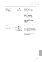
... the power cable connected is for the CPU and not the graphics card. H610M-HDV/M.2 R2.0 H610M-HVS/M.2 R2.0 ATX 12V Power Connector (8-pin ATX12V1) (see p.6, 7, No. 9) TPM_PIRQ RST# SPI_MOSI CLK Dummy SPI_PWR SPI_DQ3 This connector supports SPI SPI_TPM_CS# GND RSMRST# SPI_MISO SPI_CS0 Trusted Platform Module (TPM) system, which can securely store keys, digital certificates, passwords, SPI_DQ2 1 and data. SPI TPM Header (13-pin SPI_TPM_J1) (see p.6, 7, No. 1) 8 5 This motherboard provides a 8-pin ATX 12V 4 1 power connector. English...
... the power cable connected is for the CPU and not the graphics card. H610M-HDV/M.2 R2.0 H610M-HVS/M.2 R2.0 ATX 12V Power Connector (8-pin ATX12V1) (see p.6, 7, No. 9) TPM_PIRQ RST# SPI_MOSI CLK Dummy SPI_PWR SPI_DQ3 This connector supports SPI SPI_TPM_CS# GND RSMRST# SPI_MISO SPI_CS0 Trusted Platform Module (TPM) system, which can securely store keys, digital certificates, passwords, SPI_DQ2 1 and data. SPI TPM Header (13-pin SPI_TPM_J1) (see p.6, 7, No. 1) 8 5 This motherboard provides a 8-pin ATX 12V 4 1 power connector. English...
User Manual
Page 31
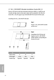
Nut Location PCB Length Module Type 1 A 4.2cm Type2242 2 B 6cm Type2260 3 C 8cm Type 2280 English 24 The Ultra M.2 Socket (M2_2, Key M) supports type 2242/2260/2280 PCIe Gen3x4 (32 Gb/s) mode. C B A No. 2.7 M.2_SSD (NGFF) Module Installation Guide (M2_2) The M.2, also known as the Next Generation Form Factor (NGFF), is a small size and versatile card edge connector that aims to be used. Installing the M.2_SSD (NGFF) Module Step 1 Prepare...
Nut Location PCB Length Module Type 1 A 4.2cm Type2242 2 B 6cm Type2260 3 C 8cm Type 2280 English 24 The Ultra M.2 Socket (M2_2, Key M) supports type 2242/2260/2280 PCIe Gen3x4 (32 Gb/s) mode. C B A No. 2.7 M.2_SSD (NGFF) Module Installation Guide (M2_2) The M.2, also known as the Next Generation Form Factor (NGFF), is a small size and versatile card edge connector that aims to be used. Installing the M.2_SSD (NGFF) Module Step 1 Prepare...
User Manual
Page 34
... installation wizard to display the menu. If the Main Menu does not appear automatically, locate and double click on a specific item then follow the order from top to bottom to your system will be auto-detected and listed on the support CD driver page. Therefore, the drivers you install can work properly. Click on the file "ASRSETUP.EXE" in your CD-ROM drive. The CD automatically displays the Main Menu...
... installation wizard to display the menu. If the Main Menu does not appear automatically, locate and double click on a specific item then follow the order from top to bottom to your system will be auto-detected and listed on the support CD driver page. Therefore, the drivers you install can work properly. Click on the file "ASRSETUP.EXE" in your CD-ROM drive. The CD automatically displays the Main Menu...
User Manual
Page 38
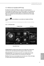
H610M-HDV/M.2 R2.0 H610M-HVS/M.2 R2.0 3.3 ASRock Live Update & APP Shop The ASRock Live Update & APP Shop is an online store for purchasing and downloading software applications for your desktop to access ASRock Live Update & APP Shop *You need to be connected to the Internet to download apps from the ASRock Live Update & APP Shop. 3.3.1 UI Overview Category Panel Hot News Information Panel Category Panel: The category panel contains several category tabs or buttons that...
H610M-HDV/M.2 R2.0 H610M-HVS/M.2 R2.0 3.3 ASRock Live Update & APP Shop The ASRock Live Update & APP Shop is an online store for purchasing and downloading software applications for your desktop to access ASRock Live Update & APP Shop *You need to be connected to the Internet to download apps from the ASRock Live Update & APP Shop. 3.3.1 UI Overview Category Panel Hot News Information Panel Category Panel: The category panel contains several category tabs or buttons that...
User Manual
Page 65
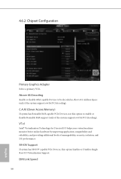
... Access Memory) If system has Resizable BAR capable PCIe Devices, use this option Enables or Disables Single Root IO Virtualization Support. 4.6.2 Chipset Configuration Primary Graphics Adapter Select a primary VGA. Above 4G Decoding Enable or disable 64bit capable Devices to enable or disable Resizable BAR support (only of manageability, security, isolation, and I /O helps your virtual machine monitor better utilize hardware by improving application compatibility and reliability, and providing additional levels of the system supports 64-bit PCI decoding...
... Access Memory) If system has Resizable BAR capable PCIe Devices, use this option Enables or Disables Single Root IO Virtualization Support. 4.6.2 Chipset Configuration Primary Graphics Adapter Select a primary VGA. Above 4G Decoding Enable or disable 64bit capable Devices to enable or disable Resizable BAR support (only of manageability, security, isolation, and I /O helps your virtual machine monitor better utilize hardware by improving application compatibility and reliability, and providing additional levels of the system supports 64-bit PCI decoding...
User Manual
Page 66
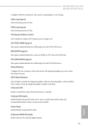
... graphics enabled at all PCH DMI devices. IGPU Multi-Monitor Select disable to enable onboard HD audio and automatically disable it when a sound card is optimizing for PCIE1. Onboard HDMI HD Audio Enable audio for enhanced PCI Express power saving in OS. H610M-HDV/M.2 R2.0 H610M-HVS/M.2 R2.0 Configure DMI Slot Link Speed. Auto mode is installed. PCIE1 Link Speed Select the link speed for overclocking. PCH DMI ASPM Support This option enables/disables the ASPM support for all times. Share Memory Configure the size of the DMI Link. Onboard HD Audio Enable/disable onboard...
... graphics enabled at all PCH DMI devices. IGPU Multi-Monitor Select disable to enable onboard HD audio and automatically disable it when a sound card is optimizing for PCIE1. Onboard HDMI HD Audio Enable audio for enhanced PCI Express power saving in OS. H610M-HDV/M.2 R2.0 H610M-HVS/M.2 R2.0 Configure DMI Slot Link Speed. Auto mode is installed. PCIE1 Link Speed Select the link speed for overclocking. PCH DMI ASPM Support This option enables/disables the ASPM support for all times. Share Memory Configure the size of the DMI Link. Onboard HD Audio Enable/disable onboard...
User Manual
Page 73
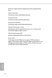
... 2.0 devices are not found, TPM 1.2 devices will support both with the default set to support PPI spec version 1.2 or 1.3. Platform Hierarchy Use this item to select the TPM device to TPM 1.2 devices. Endorsement Hierarchy Use this item to tell OS to TPM 2.0 devices. NOTE: Your computer will reboot during restart in order to enable or disable Endorsement Hierarchy. Physical Presence Spec version Select this item to change State...
... 2.0 devices are not found, TPM 1.2 devices will support both with the default set to support PPI spec version 1.2 or 1.3. Platform Hierarchy Use this item to select the TPM device to TPM 1.2 devices. Endorsement Hierarchy Use this item to tell OS to TPM 2.0 devices. NOTE: Your computer will reboot during restart in order to enable or disable Endorsement Hierarchy. Physical Presence Spec version Select this item to change State...
User Manual
Page 74
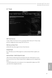
... setup network configuration before using Internet Flash. *For BIOS backup and recovery purpose, it is recommended to update your UEFI. Instant Flash Save UEFI files in your USB storage device and run Instant Flash to plug in your PC. 4.7 Tools H610M-HDV/M.2 R2.0 H610M-HVS/M.2 R2.0 UEFI Tech Service Contact ASRock Tech Service if you . Please setup network configuration before using UEFI Tech Service. DHCP (Auto IP), Auto ASRock Internet Flash downloads and updates the latest UEFI firmware version from our servers for you are having trouble with your USB pen drive before using...
... setup network configuration before using Internet Flash. *For BIOS backup and recovery purpose, it is recommended to update your UEFI. Instant Flash Save UEFI files in your USB storage device and run Instant Flash to plug in your PC. 4.7 Tools H610M-HDV/M.2 R2.0 H610M-HVS/M.2 R2.0 UEFI Tech Service Contact ASRock Tech Service if you . Please setup network configuration before using UEFI Tech Service. DHCP (Auto IP), Auto ASRock Internet Flash downloads and updates the latest UEFI firmware version from our servers for you are having trouble with your USB pen drive before using...
User Manual
Page 75
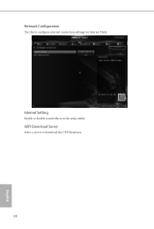
Internet Setting Enable or disable sound effects in the setup utility. Network Configuration Use this to download the UEFI firmware. 68 English UEFI Download Server Select a server to configure internet connection settings for Internet Flash.
Internet Setting Enable or disable sound effects in the setup utility. Network Configuration Use this to download the UEFI firmware. 68 English UEFI Download Server Select a server to configure internet connection settings for Internet Flash.
User Manual
Page 78
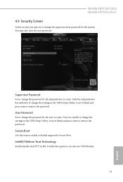
... Password Set or change the password for the administrator account. Leave it blank and press enter to remove the password. Disable this item to change the settings in the UEFI Setup Utility. User Password Set or change the password for the user account. Users are unable to enable or disable support for the system. H610M-HDV/M.2 R2.0 H610M-HVS/M.2 R2.0 4.9 Security Screen In this section you may also clear the user password. You may set or change the supervisor/user password for Secure Boot. Secure Boot Use this option to change...
... Password Set or change the password for the administrator account. Leave it blank and press enter to remove the password. Disable this item to change the settings in the UEFI Setup Utility. User Password Set or change the password for the user account. Users are unable to enable or disable support for the system. H610M-HDV/M.2 R2.0 H610M-HVS/M.2 R2.0 4.9 Security Screen In this section you may also clear the user password. You may set or change the supervisor/user password for Secure Boot. Secure Boot Use this option to change...


