
User Manual
Page 3
...Motherboard Layout 11 1.4 I/O Panel 12 2 Installation 13 2.1 Screw Holes 13 2.2 Pre-installation Precautions 13 2.3 CPU Installation 14 2.4 Installation of Heatsink and CPU fan 16 2.5 Installation of Memory Modules (DIMM 17 2.6 Expansion Slots (PCI Express Slots 18 2.7 Dual Monitor and Surround Display Features 19 2.8 Jumpers Setup 22 2.9 Onboard Headers and Connectors 23 2.10 Serial ATA (SATA) / Serial ATAII (SATAII) Hard Disks Installation 27 2.11 Hot Plug Function for SATA / SATAII HDDs 27 2.12 SATA / SATAII HDD Hot Plug Feature and Operation Guide 28 2.13 Driver Installation...
...Motherboard Layout 11 1.4 I/O Panel 12 2 Installation 13 2.1 Screw Holes 13 2.2 Pre-installation Precautions 13 2.3 CPU Installation 14 2.4 Installation of Heatsink and CPU fan 16 2.5 Installation of Memory Modules (DIMM 17 2.6 Expansion Slots (PCI Express Slots 18 2.7 Dual Monitor and Surround Display Features 19 2.8 Jumpers Setup 22 2.9 Onboard Headers and Connectors 23 2.10 Serial ATA (SATA) / Serial ATAII (SATAII) Hard Disks Installation 27 2.11 Hot Plug Function for SATA / SATAII HDDs 27 2.12 SATA / SATAII HDD Hot Plug Feature and Operation Guide 28 2.13 Driver Installation...

User Manual
Page 9
... to access ASRock Instant Flash. Due to your Apple devices, such as a profile and share with 64-bit CPU, there is subject to read the installation guide of output phases to update system BIOS without entering operating systems first like MS-DOS or Windows®. Deep Color mode will be enabled only if the display supports 12bpc in Flash ROM. In Overclocking, you can press key during the POST...
... to access ASRock Instant Flash. Due to your Apple devices, such as a profile and share with 64-bit CPU, there is subject to read the installation guide of output phases to update system BIOS without entering operating systems first like MS-DOS or Windows®. Deep Color mode will be enabled only if the display supports 12bpc in Flash ROM. In Overclocking, you can press key during the POST...
User Manual
Page 11
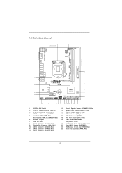
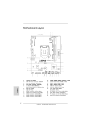
... Flash 8 SATA2 Connector (SATA2_1, Blue) 9 Chassis Fan Connector (CHA_FAN1) 10 SATA2 Connector (SATA2_0, Blue) 11 SATA2 Connector (SATA2_3, Blue) 12 SATA2 Connector (SATA2_2, Blue) 13 Chassis Speaker Header (SPEAKER 1, White) 14 System Panel Header (PANEL1, White) 15 USB 2.0 Header (USB6_7, Blue) 16 USB 2.0 Header (USB8_9, Blue) 17 COM Port Header (COM1) 18 Print Port Header (LPT1, White) 19 Front Panel Audio Header (HD_AUDIO1, White) 20 PCI Express 2.0 x1 Slot (PCIE2, White) 21 Clear CMOS Jumper (CLRCMOS1) 22 PCI Express 2.0 x16 Slot (PCIE1, Blue) 23 Power Fan Connector...
... Flash 8 SATA2 Connector (SATA2_1, Blue) 9 Chassis Fan Connector (CHA_FAN1) 10 SATA2 Connector (SATA2_0, Blue) 11 SATA2 Connector (SATA2_3, Blue) 12 SATA2 Connector (SATA2_2, Blue) 13 Chassis Speaker Header (SPEAKER 1, White) 14 System Panel Header (PANEL1, White) 15 USB 2.0 Header (USB6_7, Blue) 16 USB 2.0 Header (USB8_9, Blue) 17 COM Port Header (COM1) 18 Print Port Header (LPT1, White) 19 Front Panel Audio Header (HD_AUDIO1, White) 20 PCI Express 2.0 x1 Slot (PCIE2, White) 21 Clear CMOS Jumper (CLRCMOS1) 22 PCI Express 2.0 x16 Slot (PCIE1, Blue) 23 Power Fan Connector...
User Manual
Page 19
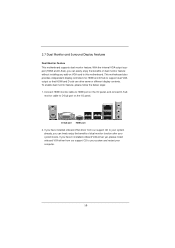
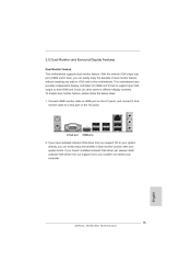
... can drive same or different display contents. D-Sub port HDMI port 2. 2.7 Dual Monitor and Surround Display Features Dual Monitor Feature This motherboard supports dual monitor feature. If you haven't installed onboard VGA driver yet, please install onboard VGA driver from our support CD to HDMI port on the I /O panel. With the internal VGA output support (HDMI and D-Sub), you can freely enjoy the benefits of dual monitor feature without installing any add-on the I /O panel, and connect D-Sub monitor cable to D-Sub port on VGA card to support dual VGA output...
... can drive same or different display contents. D-Sub port HDMI port 2. 2.7 Dual Monitor and Surround Display Features Dual Monitor Feature This motherboard supports dual monitor feature. If you haven't installed onboard VGA driver yet, please install onboard VGA driver from our support CD to HDMI port on the I /O panel. With the internal VGA output support (HDMI and D-Sub), you can freely enjoy the benefits of dual monitor feature without installing any add-on the I /O panel, and connect D-Sub monitor cable to D-Sub port on VGA card to support dual VGA output...

User Manual
Page 20
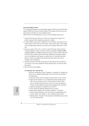
.... 20 Install the onboard VGA driver and the add-on the I /O panel, and connect D-Sub monitor cable to enter UEFI setup. C. Set the "Screen Resolution" and "Color Quality" as Secondary. Enter "Onboard VGA Share Memory" option to adjust the memory capability to [32MB], [64MB], [128MB], [256MB] or [512MB] to this monitor". Repeat steps C through E for details. 2. Install the PCI Express VGA card on PCIE1 slot. 3. Press or to D-Sub port on PCI Express VGA card driver to set up a multi-monitor display. D. G. For Windows® XP...
.... 20 Install the onboard VGA driver and the add-on the I /O panel, and connect D-Sub monitor cable to enter UEFI setup. C. Set the "Screen Resolution" and "Color Quality" as Secondary. Enter "Onboard VGA Share Memory" option to adjust the memory capability to [32MB], [64MB], [128MB], [256MB] or [512MB] to this monitor". Repeat steps C through E for details. 2. Install the PCI Express VGA card on PCIE1 slot. 3. Press or to D-Sub port on PCI Express VGA card driver to set up a multi-monitor display. D. G. For Windows® XP...

User Manual
Page 30
...;oppy diskette and copy SATA / SATAII drivers into the floppy drive. E. STEP 2: Make a SATA / SATAII driver diskette. (Please use USB floppy or floppy disk.) A. Insert the Support CD into the floppy drive, and press . Please select CD-ROM as the boot device. Then you want to install Windows® XP / XP 64-bit OS on your SATA / SATAII HDDs without RAID functions, please follow below...
...;oppy diskette and copy SATA / SATAII drivers into the floppy drive. E. STEP 2: Make a SATA / SATAII driver diskette. (Please use USB floppy or floppy disk.) A. Insert the Support CD into the floppy drive, and press . Please select CD-ROM as the boot device. Then you want to install Windows® XP / XP 64-bit OS on your SATA / SATAII HDDs without RAID functions, please follow below...
User Manual
Page 38
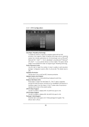
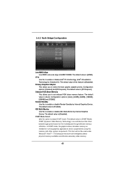
... turn on /off the MLC streamer prefetcher. Adjacent Cache Line Prefetch Use this to enable or disable CPU C3 (ACPI C2) report to OS. Set to [Enabled] if using Microsoft® Windows® XP, VistaTM, 7, or Linux kernel version 2.4.18 or higher. The default value is supported through the native processor instructions HLT and MWAIT and requires no hardware support from the chipset. 3.4.1 CPU Configuration Intel Hyper Threading Technology To enable...
... turn on /off the MLC streamer prefetcher. Adjacent Cache Line Prefetch Use this to enable or disable CPU C3 (ACPI C2) report to OS. Set to [Enabled] if using Microsoft® Windows® XP, VistaTM, 7, or Linux kernel version 2.4.18 or higher. The default value is supported through the native processor instructions HLT and MWAIT and requires no hardware support from the chipset. 3.4.1 CPU Configuration Intel Hyper Threading Technology To enable...
User Manual
Page 40
...;guration options: [Onboard] and [PCI Express]. Configuration options: [Auto], [32MB], [64MB], [128MB], [256MB] and [512MB]. The default value is [64MB]. IGD Multi-Monitor Use this feature is [Disabled]. DVMT Mode Select Use this memory with other system components. In DVMT mode, the graphics driver allocates memory as needed for running graphics applications and is [DVMT Mode]. VT-d Use this to enable or disable Intel® VT-d technology (Intel® Virtualization Technology for the motherboard...
...;guration options: [Onboard] and [PCI Express]. Configuration options: [Auto], [32MB], [64MB], [128MB], [256MB] and [512MB]. The default value is [64MB]. IGD Multi-Monitor Use this feature is [Disabled]. DVMT Mode Select Use this memory with other system components. In DVMT mode, the graphics driver allocates memory as needed for running graphics applications and is [DVMT Mode]. VT-d Use this to enable or disable Intel® VT-d technology (Intel® Virtualization Technology for the motherboard...
User Manual
Page 43
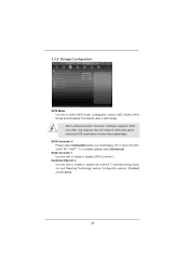
... to enable or disable SATA Controller 1. SATA Controller 1 Use this item to select SATA mode. The default value is installed, please select [Enhanced]. AHCI (Advanced Host Controller Interface) supports NCQ and other new features that will improve SATA disk performance but IDE mode does not have these advantages. Configuration options: [Disabled] and [Enabled]. 43 If native OS (Windows® XP / VistaTM / 7) is [IDE Mode]. 3.4.4 Storage Configuration SATA Mode Use this to enable or disable the S.M.A.R.T. (Self-Monitoring, Analysis, and Reporting Technology...
... to enable or disable SATA Controller 1. SATA Controller 1 Use this item to select SATA mode. The default value is installed, please select [Enhanced]. AHCI (Advanced Host Controller Interface) supports NCQ and other new features that will improve SATA disk performance but IDE mode does not have these advantages. Configuration options: [Disabled] and [Enabled]. 43 If native OS (Windows® XP / VistaTM / 7) is [IDE Mode]. 3.4.4 Storage Configuration SATA Mode Use this to enable or disable the S.M.A.R.T. (Self-Monitoring, Analysis, and Reporting Technology...
User Manual
Page 46
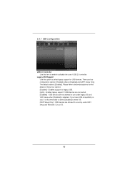
... default value is recommended to select [Disabled] to enter OS. [UEFI Setup Only] - USB devices are four configuration options: [Enabled], [Auto], [Disabled] and [UEFI Setup Only]. 3.4.7 USB Configuration USB 2.0 Controller Use this option to select legacy support for USB devices. There are allowed to use under UEFI setup and Windows / Linux OS. 46 Enables legacy support if USB devices are not allowed to use of these four options: [Enabled] - USB devices are connected. [Disabled] - Legacy USB Support Use this item to below descriptions for legacy USB. [Auto...
... default value is recommended to select [Disabled] to enter OS. [UEFI Setup Only] - USB devices are four configuration options: [Enabled], [Auto], [Disabled] and [UEFI Setup Only]. 3.4.7 USB Configuration USB 2.0 Controller Use this option to select legacy support for USB devices. There are allowed to use under UEFI setup and Windows / Linux OS. 46 Enables legacy support if USB devices are not allowed to use of these four options: [Enabled] - USB devices are connected. [Disabled] - Legacy USB Support Use this item to below descriptions for legacy USB. [Auto...

User Manual
Page 51
... 4: Software Support 4.1 Install Operating System This motherboard supports various Microsoft® Windows® operating systems: 7 / 7 64-bit / VistaTM / VistaTM 64-bit / XP / XP 64-bit. Refer to your OS documentation for more about ASRock, welcome to display the menus. 4.2.2 Drivers Menu The Drivers Menu shows the available devices drivers if the system detects installed devices. The CD automatically displays the Main Menu if "AUTORUN" is enabled in your CD-ROM drive. Please install the necessary drivers to install...
... 4: Software Support 4.1 Install Operating System This motherboard supports various Microsoft® Windows® operating systems: 7 / 7 64-bit / VistaTM / VistaTM 64-bit / XP / XP 64-bit. Refer to your OS documentation for more about ASRock, welcome to display the menus. 4.2.2 Drivers Menu The Drivers Menu shows the available devices drivers if the system detects installed devices. The CD automatically displays the Main Menu if "AUTORUN" is enabled in your CD-ROM drive. Please install the necessary drivers to install...
Quick Installation Guide
Page 2
... (SATA2_1, Blue) Chassis Fan Connector (CHA_FAN1) SATA2 Connector (SATA2_0, Blue) SATA2 Connector (SATA2_3, Blue) SATA2 Connector (SATA2_2, Blue) 13 14 15 16 17 18 19 20 21 22 23 Chassis Speaker Header (SPEAKER 1, White) System Panel Header (PANEL1, White) USB 2.0 Header (USB6_7, Blue) USB 2.0 Header (USB8_9, Blue) COM Port Header (COM1) Print Port Header (LPT1, White) Front Panel Audio Header (HD_AUDIO1, White) PCI Express 2.0 x1 Slot (PCIE2, White) Clear CMOS Jumper (CLRCMOS1) PCI Express 2.0 x16 Slot (PCIE1, Blue) Power Fan Connector (PWR_FAN1) English 2 ASRock H61M-HGS Motherboard
... (SATA2_1, Blue) Chassis Fan Connector (CHA_FAN1) SATA2 Connector (SATA2_0, Blue) SATA2 Connector (SATA2_3, Blue) SATA2 Connector (SATA2_2, Blue) 13 14 15 16 17 18 19 20 21 22 23 Chassis Speaker Header (SPEAKER 1, White) System Panel Header (PANEL1, White) USB 2.0 Header (USB6_7, Blue) USB 2.0 Header (USB8_9, Blue) COM Port Header (COM1) Print Port Header (LPT1, White) Front Panel Audio Header (HD_AUDIO1, White) PCI Express 2.0 x1 Slot (PCIE2, White) Clear CMOS Jumper (CLRCMOS1) PCI Express 2.0 x16 Slot (PCIE1, Blue) Power Fan Connector (PWR_FAN1) English 2 ASRock H61M-HGS Motherboard
Quick Installation Guide
Page 4
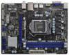
... quality control. You may find the latest VGA cards and CPU support lists on ASRock website without notice. English 4 ASRock H61M-HGS Motherboard www.asrock.com/support/index.asp 1.1 Package Contents ASRock H61M-HGS Motherboard (Micro ATX Form Factor: 8.9-in x 6.8-in, 22.6 cm x 17.3 cm) ASRock H61M-HGS Quick Installation Guide ASRock H61M-HGS Support CD 2 x Serial ATA (SATA) Data Cables (Optional) 1 x I/O Panel Shield ASRock Reminds You...To get better performance in Windows® 7 / 7 64-bit / VistaTM / VistaTM 64bit, it is recommended to change without...
... quality control. You may find the latest VGA cards and CPU support lists on ASRock website without notice. English 4 ASRock H61M-HGS Motherboard www.asrock.com/support/index.asp 1.1 Package Contents ASRock H61M-HGS Motherboard (Micro ATX Form Factor: 8.9-in x 6.8-in, 22.6 cm x 17.3 cm) ASRock H61M-HGS Quick Installation Guide ASRock H61M-HGS Support CD 2 x Serial ATA (SATA) Data Cables (Optional) 1 x I/O Panel Shield ASRock Reminds You...To get better performance in Windows® 7 / 7 64-bit / VistaTM / VistaTM 64bit, it is recommended to change without...

Quick Installation Guide
Page 5
... CAUTION 3) - 1 x PCI Express 2.0 x16 slot (blue @ x16 mode) - 1 x PCI Express 2.0 x1 slot - Realtek RTL8111E - Supports PXE Chipset Memory Expansion Slot Graphics Audio LAN 5 ASRock H61M-HGS Motherboard English Supports 2nd Generation Intel® CoreTM i7 / i5 / i3 in Visuals: Intel® Quick Sync Video, Intel® Clear Video HD Technology, Intel® HD Graphics 2000/3000, Intel® Advanced Vector Extensions (AVX) - Supports Auto Lip Sync, Deep Color (12bpc), xvYCC and HBR (High Bit Rate Audio) with HDMI port - 1.2 Platform CPU Specifications - Supports Intel...
... CAUTION 3) - 1 x PCI Express 2.0 x16 slot (blue @ x16 mode) - 1 x PCI Express 2.0 x1 slot - Realtek RTL8111E - Supports PXE Chipset Memory Expansion Slot Graphics Audio LAN 5 ASRock H61M-HGS Motherboard English Supports 2nd Generation Intel® CoreTM i7 / i5 / i3 in Visuals: Intel® Quick Sync Video, Intel® Clear Video HD Technology, Intel® HD Graphics 2000/3000, Intel® Advanced Vector Extensions (AVX) - Supports Auto Lip Sync, Deep Color (12bpc), xvYCC and HBR (High Bit Rate Audio) with HDMI port - 1.2 Platform CPU Specifications - Supports Intel...

Quick Installation Guide
Page 6
...Wake Up Events - Boot Failure Guard (B.F.G.) English 6 ASRock H61M-HGS Motherboard Supports jumperfree - OEM and Trial; Trial; Front panel audio connector - 2 x USB 2.0 headers (support 4 USB 2.0 ports) - 32Mb AMI BIOS - Drivers, Utilities, AntiVirus Software (Trial Version), CyberLink MediaEspresso 6.5 Trial, ASRock Software Suite (CyberLink DVD Suite - ASRock Instant Boot - HD Audio Jack: Line in/Front Speaker/Microphone - 4 x SATA2 3.0 Gb/s connectors, support NCQ, AHCI and Hot Plug functions - 1 x Print Port header - 1 x COM port header - CPU/Chassis/Power FAN...
...Wake Up Events - Boot Failure Guard (B.F.G.) English 6 ASRock H61M-HGS Motherboard Supports jumperfree - OEM and Trial; Trial; Front panel audio connector - 2 x USB 2.0 headers (support 4 USB 2.0 ports) - 32Mb AMI BIOS - Drivers, Utilities, AntiVirus Software (Trial Version), CyberLink MediaEspresso 6.5 Trial, ASRock Software Suite (CyberLink DVD Suite - ASRock Instant Boot - HD Audio Jack: Line in/Front Speaker/Microphone - 4 x SATA2 3.0 Gb/s connectors, support NCQ, AHCI and Hot Plug functions - 1 x Print Port header - 1 x COM port header - CPU/Chassis/Power FAN...
Quick Installation Guide
Page 8
... of your BIOS only in Flash ROM. About the setting of "Hyper Threading Technology", please check page 38 of output phases to improve efficiency when the CPU cores are allowed to read the installation guide of charging your Apple devices, such as a profile and share with 64-bit CPU, there is including Hardware Monitor, Fan Control, Overclocking, OC DNA and IES. This motherboard supports Dual Channel Memory Technology. CAUTION...
... of your BIOS only in Flash ROM. About the setting of "Hyper Threading Technology", please check page 38 of output phases to improve efficiency when the CPU cores are allowed to read the installation guide of charging your Apple devices, such as a profile and share with 64-bit CPU, there is including Hardware Monitor, Fan Control, Overclocking, OC DNA and IES. This motherboard supports Dual Channel Memory Technology. CAUTION...
Quick Installation Guide
Page 15
... I /O panel, and connect D-Sub monitor cable to support dual VGA output so that HDMI and D-sub can easily enjoy the benefits of dual monitor function after your computer. 15 ASRock H61M-HGS Motherboard English To enable dual monitor feature, please follow the below steps: 1. D-Sub port HDMI port 2. If you can drive same or different display contents. With the internal VGA output support (HDMI and D-Sub), you have installed onboard VGA driver from our support CD to this motherboard. This motherboard...
... I /O panel, and connect D-Sub monitor cable to support dual VGA output so that HDMI and D-sub can easily enjoy the benefits of dual monitor function after your computer. 15 ASRock H61M-HGS Motherboard English To enable dual monitor feature, please follow the below steps: 1. D-Sub port HDMI port 2. If you can drive same or different display contents. With the internal VGA output support (HDMI and D-Sub), you have installed onboard VGA driver from our support CD to this motherboard. This motherboard...
Quick Installation Guide
Page 16
.... Install the onboard VGA driver and the add-on each monitor. Set the "Screen Resolution" and "Color Quality" as Secondary. English 16 ASRock H61M-HGS Motherboard Surround Display Feature This motherboard supports surround display upgrade. Connect HDMI monitor cable to HDMI port on the I/O panel, and connect D-Sub monitor cable to display a large number on PCI Express VGA card driver to be designated as appropriate for the diaplay icon identified by the number 2. Boot your system. Set up a surround display environment: 1. A. If you use...
.... Install the onboard VGA driver and the add-on each monitor. Set the "Screen Resolution" and "Color Quality" as Secondary. English 16 ASRock H61M-HGS Motherboard Surround Display Feature This motherboard supports surround display upgrade. Connect HDMI monitor cable to HDMI port on the I/O panel, and connect D-Sub monitor cable to display a large number on PCI Express VGA card driver to be designated as appropriate for the diaplay icon identified by the number 2. Boot your system. Set up a surround display environment: 1. A. If you use...
Quick Installation Guide
Page 22
Using SATA / SATAII HDDs without RAID functions, please follow below steps. Enter UEFI SETUP UTILITY Advanced screen SATA Configuration. English 22 ASRock H61M-HGS Motherboard Serial port Header (9-pin COM1) (see p.2 No. 2) Please connect an ATX 12V power supply to this connector. Then, the drivers compatible to your optical drive first. Please follow below procedures according to the OS you install. 2.9.1 Installing Windows® XP / XP 64-bit Without RAID Functions If you want to install Windows® 7 / 7 64-bit / VistaTM / VistaTM...
Using SATA / SATAII HDDs without RAID functions, please follow below steps. Enter UEFI SETUP UTILITY Advanced screen SATA Configuration. English 22 ASRock H61M-HGS Motherboard Serial port Header (9-pin COM1) (see p.2 No. 2) Please connect an ATX 12V power supply to this connector. Then, the drivers compatible to your optical drive first. Please follow below procedures according to the OS you install. 2.9.1 Installing Windows® XP / XP 64-bit Without RAID Functions If you want to install Windows® 7 / 7 64-bit / VistaTM / VistaTM...
Quick Installation Guide
Page 24
... Main Menu does not appear automatically, locate and double-click on the motherboard stores BIOS Setup Utility. 3. The Support CD that will display the Main Menu automatically if "AUTORUN" is a menu-driven program, which allows you start up the computer, please press or during the Power-On-Self-Test (POST) to the User Manual (PDF file) contained in your CD-ROM drive. otherwise, POST continues with the motherboard contains necessary drivers and useful utilities...
... Main Menu does not appear automatically, locate and double-click on the motherboard stores BIOS Setup Utility. 3. The Support CD that will display the Main Menu automatically if "AUTORUN" is a menu-driven program, which allows you start up the computer, please press or during the Power-On-Self-Test (POST) to the User Manual (PDF file) contained in your CD-ROM drive. otherwise, POST continues with the motherboard contains necessary drivers and useful utilities...


