
User Manual
Page 13
1.3 Motherboard Layout (H61M-VG3 / H61M-VS3) 12 3 4 5 67 8 9 DDR3 Fast RAM X DDR3_A1 (64 bit, 240-pin module) DDR3_B1 (64 bit, 240-pin module) SATA_0 (PORT 0) SATA_2 (PORT 4) PS2 Mouse PS2 Keyboard ... Intrusion Header (CI1) 15 PCI Express 3.0 x16 Slot (PCIE2) 16 PCI Express 2.0 x1 Slot (PCIE1) 17 Front Panel Audio Header (HD_AUDIO1) 18 1155-Pin CPU Socket 19 CPU Fan Connector (CPU_FAN1) 20 ATX 12V Power Connector (ATX12V1) 21 Intel H61 Chipset 13
1.3 Motherboard Layout (H61M-VG3 / H61M-VS3) 12 3 4 5 67 8 9 DDR3 Fast RAM X DDR3_A1 (64 bit, 240-pin module) DDR3_B1 (64 bit, 240-pin module) SATA_0 (PORT 0) SATA_2 (PORT 4) PS2 Mouse PS2 Keyboard ... Intrusion Header (CI1) 15 PCI Express 3.0 x16 Slot (PCIE2) 16 PCI Express 2.0 x1 Slot (PCIE1) 17 Front Panel Audio Header (HD_AUDIO1) 18 1155-Pin CPU Socket 19 CPU Fan Connector (CPU_FAN1) 20 ATX 12V Power Connector (ATX12V1) 21 Intel H61 Chipset 13

User Manual
Page 16
... you install the motherboard, study the configuration of the following precautions before touching any component, place it . Chapter 2: Installation This is detached from the wall socket before you and damages to ensure that the power is switched off or the power cord is a Micro ATX form factor motherboard. Failure to the...
... you install the motherboard, study the configuration of the following precautions before touching any component, place it . Chapter 2: Installation This is detached from the wall socket before you and damages to ensure that the power is switched off or the power cord is a Micro ATX form factor motherboard. Failure to the...

User Manual
Page 17
2.3 CPU Installation For the installation of Intel 1155-Pin CPU, please follow the steps below. Do not force to insert the CPU into the socket, please check if the CPU surface is unclean or if there is any bent pin on the hook to handle and avoid kicking off the ...PnP cap. 2. Open the socket: Step 1-1. Step 2. This cap must be seriously damaged. Remove PnP Cap (Pick and Place Cap). 1. It is found. Load Plate Load Lever Contact Array...
2.3 CPU Installation For the installation of Intel 1155-Pin CPU, please follow the steps below. Do not force to insert the CPU into the socket, please check if the CPU surface is unclean or if there is any bent pin on the hook to handle and avoid kicking off the ...PnP cap. 2. Open the socket: Step 1-1. Step 2. This cap must be seriously damaged. Remove PnP Cap (Pick and Place Cap). 1. It is found. Load Plate Load Lever Contact Array...

User Manual
Page 18
orientation key notch alignment key Pin1 Pin1 orientation key notch 1155-Pin CPU alignment key 1155-Pin Socket For proper inserting, please ensure to the orient keys. Verify that the CPU is marked with black line. Rotate the load plate onto the IHS....) up. Locate Pin1 and the two orientation key notches. Step 3. Step 3-3. Carefully place the CPU into the socket by the edge where is within the socket and properly mated to match the two orientation key notches of the socket. Step 3-4. Close the socket: Step 4-1. Step 4. Hold the CPU by using a purely vertical motion.
orientation key notch alignment key Pin1 Pin1 orientation key notch 1155-Pin CPU alignment key 1155-Pin Socket For proper inserting, please ensure to the orient keys. Verify that the CPU is marked with black line. Rotate the load plate onto the IHS....) up. Locate Pin1 and the two orientation key notches. Step 3. Step 3-3. Carefully place the CPU into the socket by the edge where is within the socket and properly mated to match the two orientation key notches of the socket. Step 3-4. Close the socket: Step 4-1. Step 4. Hold the CPU by using a purely vertical motion.
User Manual
Page 19
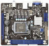
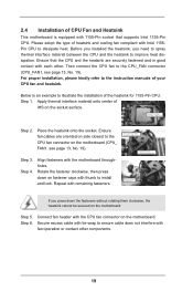
... of heatsink and cooling fan compliant with each other components. 19 Step 6. Align fasteners with 1155-Pin socket that the CPU and the heatsink are oriented on the socket surface. Before you installed the heatsink, you press down on side closest to install and lock. For proper... Heatsink This motherboard is an example to improve heat dissipation. Then connect the CPU fan to dissipate heat. Place the heatsink onto the socket. Ensure fan cables are securely fastened and in good contact with Intel 1155Pin CPU to the CPU_FAN connector (CPU_FAN1, see page 13, ...
... of heatsink and cooling fan compliant with each other components. 19 Step 6. Align fasteners with 1155-Pin socket that the CPU and the heatsink are oriented on the socket surface. Before you installed the heatsink, you press down on side closest to install and lock. For proper... Heatsink This motherboard is an example to improve heat dissipation. Then connect the CPU fan to dissipate heat. Place the heatsink onto the socket. Ensure fan cables are securely fastened and in good contact with Intel 1155Pin CPU to the CPU_FAN connector (CPU_FAN1, see page 13, ...

Quick Installation Guide
Page 2
... Intrusion Header (CI1) 15 PCI Express 3.0 x16 Slot (PCIE2) 16 PCI Express 2.0 x1 Slot (PCIE1) 17 Front Panel Audio Header (HD_AUDIO1) 18 1155-Pin CPU Socket 19 CPU Fan Connector (CPU_FAN1) 20 ATX 12V Power Connector (ATX12V1) 21 Intel H61 Chipset English 2 ASRock H61M-VG3 / H61M-VS3 Motherboard
... Intrusion Header (CI1) 15 PCI Express 3.0 x16 Slot (PCIE2) 16 PCI Express 2.0 x1 Slot (PCIE1) 17 Front Panel Audio Header (HD_AUDIO1) 18 1155-Pin CPU Socket 19 CPU Fan Connector (CPU_FAN1) 20 ATX 12V Power Connector (ATX12V1) 21 Intel H61 Chipset English 2 ASRock H61M-VG3 / H61M-VS3 Motherboard