User Manual
Page 4
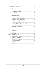
...UEFI SETUP UTILITY 44 3.1 Introduction 44 3.1.1 UEFI Menu Bar 44 3.1.2 Navigation Keys 45 3.2 Main Screen 45 3.3 OC Tweaker Screen 47 3.4 Advanced Screen 51 3.4.1 CPU Configuration 52 3.4.2 North Bridge Configuration 54 3.4.3 South Bridge Configuration 55 3.4.4 Storage Configuration 56 3.4.5 Intel(R) Rapid Start Technology 57 3.4.6 Intel(R) Smart Connect Technology 58 3.4.7 ACPI Configuration 59 3.4.8 USB Configuration 60 3.5 Tool 61 3.6 Hardware Health Event Monitoring Screen 63 3.7 Boot Screen 64 3.8 Security Screen 66 3.9 Exit Screen 67 4 Software Support 68 4.1 Install...
...UEFI SETUP UTILITY 44 3.1 Introduction 44 3.1.1 UEFI Menu Bar 44 3.1.2 Navigation Keys 45 3.2 Main Screen 45 3.3 OC Tweaker Screen 47 3.4 Advanced Screen 51 3.4.1 CPU Configuration 52 3.4.2 North Bridge Configuration 54 3.4.3 South Bridge Configuration 55 3.4.4 Storage Configuration 56 3.4.5 Intel(R) Rapid Start Technology 57 3.4.6 Intel(R) Smart Connect Technology 58 3.4.7 ACPI Configuration 59 3.4.8 USB Configuration 60 3.5 Tool 61 3.6 Hardware Health Event Monitoring Screen 63 3.7 Boot Screen 64 3.8 Security Screen 66 3.9 Exit Screen 67 4 Software Support 68 4.1 Install...

User Manual
Page 5
... updated, the content of the Support CD. Chapter 1: Introduction Thank you for specific information about the model you require technical support related to the hardware installation. www.asrock.com/support/index.asp 1.1 Package Contents ASRock H61M-VG3 / H61M-VS3 Motherboard (Micro ATX Form Factor) ASRock H61M-VG3 / H61M-VS3 Quick Installation Guide ASRock H61M-VG3 / H61M-VS3 Support CD 2 x Serial ATA (SATA) Data Cables (Optional) 1 x I/O Panel Shield ASRock Reminds You... ASRock website http://www.asrock.com If you are using. Because the motherboard specifications and the BIOS...
... updated, the content of the Support CD. Chapter 1: Introduction Thank you for specific information about the model you require technical support related to the hardware installation. www.asrock.com/support/index.asp 1.1 Package Contents ASRock H61M-VG3 / H61M-VS3 Motherboard (Micro ATX Form Factor) ASRock H61M-VG3 / H61M-VS3 Quick Installation Guide ASRock H61M-VG3 / H61M-VS3 Support CD 2 x Serial ATA (SATA) Data Cables (Optional) 1 x I/O Panel Shield ASRock Reminds You... ASRock website http://www.asrock.com If you are using. Because the motherboard specifications and the BIOS...
User Manual
Page 6
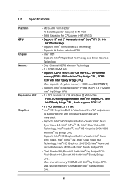
...; InTruTM 3D, Intel® Clear Video HD Technology, Intel® InsiderTM, Intel® HD Graphics 2500/4000 with Intel® Sandy Bridge CPU - Supports Intel® Rapid Start Technology and Smart Connect Technology - Max. All Solid Capacitor design (H61M-VG3) - Supports Intel® HD Graphics Built-in LGA1155 Package - shared memory 1760MB with Intel® Sandy Bridge CPU. 6 1.2 Specifications Platform CPU Chipset Memory Expansion Slot Graphics - Solid Capacitor for CPU power (H61M-VS3) - Supports 3rd and 2nd Generation...
...; InTruTM 3D, Intel® Clear Video HD Technology, Intel® InsiderTM, Intel® HD Graphics 2500/4000 with Intel® Sandy Bridge CPU - Supports Intel® Rapid Start Technology and Smart Connect Technology - Max. All Solid Capacitor design (H61M-VG3) - Supports Intel® HD Graphics Built-in LGA1155 Package - shared memory 1760MB with Intel® Sandy Bridge CPU. 6 1.2 Specifications Platform CPU Chipset Memory Expansion Slot Graphics - Solid Capacitor for CPU power (H61M-VS3) - Supports 3rd and 2nd Generation...
User Manual
Page 7
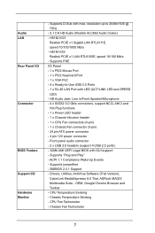
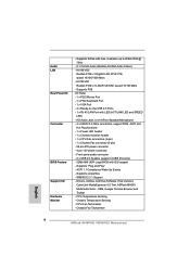
...ASRock MAGIX Multimedia Suite - H61M-VG3 Realtek PCIE x1 Gigabit LAN RTL8111E, speed 10/100/1000 Mb/s - HD Audio Jack: Line in/Front Speaker/Microphone - 4 x SATA2 3.0 Gb/s connectors, support NCQ, AHCI and Hot Plug functions - 1 x Power LED header - 1 x Chassis Intrusion header - 1 x CPU Fan connectors (4-pin) - 1 x Chassis Fan connector (3-pin) - 24 pin ATX power connector - 4 pin 12V power connector - resolution up to -Use USB 2.0 Ports - 1 x RJ-45 LAN Port with LED (ACT/LINK LED and SPEED LED) - Audio LAN Rear Panel I /O Panel - 1 x PS/2 Mouse Port - 1 x PS/2 Keyboard Port - 1 x VGA Port...
...ASRock MAGIX Multimedia Suite - H61M-VG3 Realtek PCIE x1 Gigabit LAN RTL8111E, speed 10/100/1000 Mb/s - HD Audio Jack: Line in/Front Speaker/Microphone - 4 x SATA2 3.0 Gb/s connectors, support NCQ, AHCI and Hot Plug functions - 1 x Power LED header - 1 x Chassis Intrusion header - 1 x CPU Fan connectors (4-pin) - 1 x Chassis Fan connector (3-pin) - 24 pin ATX power connector - 4 pin 12V power connector - resolution up to -Use USB 2.0 Ports - 1 x RJ-45 LAN Port with LED (ACT/LINK LED and SPEED LED) - Audio LAN Rear Panel I /O Panel - 1 x PS/2 Mouse Port - 1 x PS/2 Keyboard Port - 1 x VGA Port...

User Manual
Page 9
...-bit CPU. In Fan Control, it fully utilizes the memory space that the USB flash drive or hard drive must use FAT32/16/12 file system. 9 ASRock Instant Boot ASRock Instant Boot allows you to ne-tune different system functions in a user-friendly interface, which normally enable the Sleep/Standby and Hibernation modes in Windows® to enter your system. This convenient BIOS update tool allows you to save the new BIOS file to access ASRock Instant Flash. 1.3 Unique Features ASRock...
...-bit CPU. In Fan Control, it fully utilizes the memory space that the USB flash drive or hard drive must use FAT32/16/12 file system. 9 ASRock Instant Boot ASRock Instant Boot allows you to ne-tune different system functions in a user-friendly interface, which normally enable the Sleep/Standby and Hibernation modes in Windows® to enter your system. This convenient BIOS update tool allows you to save the new BIOS file to access ASRock Instant Flash. 1.3 Unique Features ASRock...

User Manual
Page 13
... SPI Flash 2 SATA2 Connector (SATA_1 (PORT 1)) 3 SATA2 Connector (SATA_0 (PORT 0)) 4 SATA2 Connector (SATA_2 (PORT 4)) 5 SATA2 Connector (SATA_3 (PORT 5)) 6 USB 2.0 Header (USB6_7) 7 USB 2.0 Header (USB4_5) 8 ATX Power Connector (ATXPWR1) 9 2 x 240-pin DDR3 DIMM Slots (Dual Channel: DDR3_A1, DDR3_B1) 10 Clear CMOS Jumper (CLRCMOS1) 11 Power LED Header (PLED1) 12 System Panel Header (PANEL1) 13 Chassis Fan Connector (CHA_FAN1) 14 Chassis Intrusion Header (CI1) 15 PCI Express 3.0 x16 Slot (PCIE2) 16 PCI Express 2.0 x1 Slot (PCIE1) 17 Front Panel Audio Header (HD_AUDIO1) 18 1155-Pin CPU Socket...
... SPI Flash 2 SATA2 Connector (SATA_1 (PORT 1)) 3 SATA2 Connector (SATA_0 (PORT 0)) 4 SATA2 Connector (SATA_2 (PORT 4)) 5 SATA2 Connector (SATA_3 (PORT 5)) 6 USB 2.0 Header (USB6_7) 7 USB 2.0 Header (USB4_5) 8 ATX Power Connector (ATXPWR1) 9 2 x 240-pin DDR3 DIMM Slots (Dual Channel: DDR3_A1, DDR3_B1) 10 Clear CMOS Jumper (CLRCMOS1) 11 Power LED Header (PLED1) 12 System Panel Header (PANEL1) 13 Chassis Fan Connector (CHA_FAN1) 14 Chassis Intrusion Header (CI1) 15 PCI Express 3.0 x16 Slot (PCIE2) 16 PCI Express 2.0 x1 Slot (PCIE1) 17 Front Panel Audio Header (HD_AUDIO1) 18 1155-Pin CPU Socket...
User Manual
Page 22
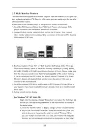
... motherboard. 4. 2.7 Multi Monitor Feature This motherboard supports multi monitor upgrade. Boot your card, one monitor will always be your system. Set up a multi monitor environment: 1. With the internal VGA output support and external add-on PCIE2 slot. Enter "Onboard VGA Share Memory" option to adjust the memory capability to [32MB], [64MB], [128MB], [256MB] or [512MB] to your primary monitor, and then select "Primary". Install the onboard VGA driver and the add-on each monitor. A. Right-click the display...
... motherboard. 4. 2.7 Multi Monitor Feature This motherboard supports multi monitor upgrade. Boot your card, one monitor will always be your system. Set up a multi monitor environment: 1. With the internal VGA output support and external add-on PCIE2 slot. Enter "Onboard VGA Share Memory" option to adjust the memory capability to [32MB], [64MB], [128MB], [256MB] or [512MB] to your primary monitor, and then select "Primary". Install the onboard VGA driver and the add-on each monitor. A. Right-click the display...

User Manual
Page 32
... support CD driver page. E. Therefore, the drivers you install can be auto-detected and listed on your SATA / SATA2 HDDs without RAID functions, please follow below procedures according to the OS you install. 2.14.1 Installing Windows® XP / XP 64-bit Without RAID Functions If you want to [AHCI]. A. B. STEP 2: Make a SATA / SATA2 driver diskette. (Please use an USB floppy or a floppy disk.) A. C. Then you want to install those required drivers. Enter UEFI SETUP UTILITY Advanced screen Storage Configuration. Formatting the floppy...
... support CD driver page. E. Therefore, the drivers you install can be auto-detected and listed on your SATA / SATA2 HDDs without RAID functions, please follow below procedures according to the OS you install. 2.14.1 Installing Windows® XP / XP 64-bit Without RAID Functions If you want to [AHCI]. A. B. STEP 2: Make a SATA / SATA2 driver diskette. (Please use an USB floppy or a floppy disk.) A. C. Then you want to install those required drivers. Enter UEFI SETUP UTILITY Advanced screen Storage Configuration. Formatting the floppy...
User Manual
Page 52
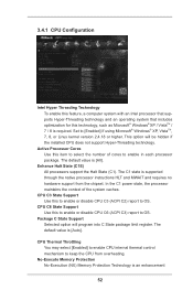
... each processor package. CPU C3 State Support Use this to enable or disable CPU C6 (ACPI C3) report to [Enabled] if using Microsoft® Windows® XP, VistaTM, 7, 8, or Linux kernel version 2.4.18 or higher. Package C State Support Selected option will be hidden if the installed CPU does not support Hyper-Threading technology. The default value is required. No-Execute Memory Protection No-Execution (NX) Memory Protection Technology is an enhancement 52 Set...
... each processor package. CPU C3 State Support Use this to enable or disable CPU C6 (ACPI C3) report to [Enabled] if using Microsoft® Windows® XP, VistaTM, 7, 8, or Linux kernel version 2.4.18 or higher. Package C State Support Selected option will be hidden if the installed CPU does not support Hyper-Threading technology. The default value is required. No-Execute Memory Protection No-Execution (NX) Memory Protection Technology is an enhancement 52 Set...
User Manual
Page 54
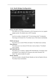
... Internal Graphics Device. PCIE2 Link Speed This allows you to set onboard VGA share memory feature. The default value is [Enabled]. 54 Render Standby Use this feature is [PCI Express]. The default value is [Enabled]. VT-d Use this option. Share Memory This allows you to select PCIE2 Link Speed. If you install the PCI Express card under Windows® XP / VistaTM OS, please disable this to enable or disable Intel® VT-d technology (Intel® Virtualization Technology for Directed I/O). The default...
... Internal Graphics Device. PCIE2 Link Speed This allows you to set onboard VGA share memory feature. The default value is [Enabled]. 54 Render Standby Use this feature is [PCI Express]. The default value is [Enabled]. VT-d Use this option. Share Memory This allows you to select PCIE2 Link Speed. If you install the PCI Express card under Windows® XP / VistaTM OS, please disable this to enable or disable Intel® VT-d technology (Intel® Virtualization Technology for Directed I/O). The default...

User Manual
Page 56
... SATA disk performance but IDE mode does not have these advantages. Configuration options: [Disabled] and [Enabled]. 56 The default value is [AHCI Mode]. Use this item to select SATA mode. SATA Mode Selection Use this to enable or disable the S.M.A.R.T. (Self-Monitoring, Analysis, and Reporting Technology) feature. Hard Disk S.M.A.R.T. SATA Aggressive Link Power Management Use this item to enable or disable the SATA Controller feature. Configuration options: [IDE Mode], [AHCI Mode] and [Disabled]. 3.4.4 Storage Configuration SATA Controller(s) Use this item to configure SATA...
... SATA disk performance but IDE mode does not have these advantages. Configuration options: [Disabled] and [Enabled]. 56 The default value is [AHCI Mode]. Use this item to select SATA mode. SATA Mode Selection Use this to enable or disable the S.M.A.R.T. (Self-Monitoring, Analysis, and Reporting Technology) feature. Hard Disk S.M.A.R.T. SATA Aggressive Link Power Management Use this item to enable or disable the SATA Controller feature. Configuration options: [IDE Mode], [AHCI Mode] and [Disabled]. 3.4.4 Storage Configuration SATA Controller(s) Use this item to configure SATA...

User Manual
Page 60
Enables legacy support if USB devices are four configuration options: [Enabled], [Auto], [Disabled] and [UEFI Setup Only]. There are connected. [Disabled] - Enables support for the details of USB 2.0 controller. The default value is selected. USB devices are allowed to enter OS. [UEFI Setup Only] - If you enable Fast Boot option. USB devices are not allowed to use under UEFI setup and Windows / Linux OS. 60 The default value is recommended to select [Disabled] to use of these four options: [Enabled] - Please refer to select legacy support for USB devices. CSM...
Enables legacy support if USB devices are four configuration options: [Enabled], [Auto], [Disabled] and [UEFI Setup Only]. There are connected. [Disabled] - Enables support for the details of USB 2.0 controller. The default value is selected. USB devices are allowed to enter OS. [UEFI Setup Only] - If you enable Fast Boot option. USB devices are not allowed to use under UEFI setup and Windows / Linux OS. 60 The default value is recommended to select [Disabled] to use of these four options: [Enabled] - Please refer to select legacy support for USB devices. CSM...
User Manual
Page 63
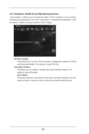
... only when the case open detection feature. Use this section, it allows you to monitor the status of the hardware on your system, including the parameters of previous chassis intrusion status. 63 Configuration options: [Full On] and [Automatic Mode]. 3.6 Hardware Health Event Monitoring Screen In this option to keep or clear the record of the CPU temperature, motherboard temperature, CPU fan speed, chassis fan speed, and the critical voltage. The default is value [Enabled].
... only when the case open detection feature. Use this section, it allows you to monitor the status of the hardware on your system, including the parameters of previous chassis intrusion status. 63 Configuration options: [Full On] and [Automatic Mode]. 3.6 Hardware Health Event Monitoring Screen In this option to keep or clear the record of the CPU temperature, motherboard temperature, CPU fan speed, chassis fan speed, and the critical voltage. The default is value [Enabled].

User Manual
Page 68
... Main Menu if "AUTORUN" is enabled in your CD-ROM drive. Because motherboard settings and hardware options vary, use the setup procedures in the Support CD to visit ASRock's website at http://www.asrock.com; Click on the file "ASSETUP.EXE" from the BIN folder in this chapter for more about ASRock, welcome to display the menus. 4.2.2 Drivers Menu The Drivers Menu shows the available devices drivers if the system detects installed devices. Please install...
... Main Menu if "AUTORUN" is enabled in your CD-ROM drive. Because motherboard settings and hardware options vary, use the setup procedures in the Support CD to visit ASRock's website at http://www.asrock.com; Click on the file "ASSETUP.EXE" from the BIN folder in this chapter for more about ASRock, welcome to display the menus. 4.2.2 Drivers Menu The Drivers Menu shows the available devices drivers if the system detects installed devices. Please install...

Quick Installation Guide
Page 2
... (PORT 5)) 6 USB 2.0 Header (USB6_7) 7 USB 2.0 Header (USB4_5) 8 ATX Power Connector (ATXPWR1) 9 2 x 240-pin DDR3 DIMM Slots (Dual Channel: DDR3_A1, DDR3_B1) 10 Clear CMOS Jumper (CLRCMOS1) 11 Power LED Header (PLED1) 12 System Panel Header (PANEL1) 13 Chassis Fan Connector (CHA_FAN1) 14 Chassis Intrusion Header (CI1) 15 PCI Express 3.0 x16 Slot (PCIE2) 16 PCI Express 2.0 x1 Slot (PCIE1) 17 Front Panel Audio Header (HD_AUDIO1) 18 1155-Pin CPU Socket 19 CPU Fan Connector (CPU_FAN1) 20 ATX 12V Power Connector (ATX12V1) 21 Intel H61 Chipset English 2 ASRock H61M-VG3 / H61M-VS3 Motherboard
... (PORT 5)) 6 USB 2.0 Header (USB6_7) 7 USB 2.0 Header (USB4_5) 8 ATX Power Connector (ATXPWR1) 9 2 x 240-pin DDR3 DIMM Slots (Dual Channel: DDR3_A1, DDR3_B1) 10 Clear CMOS Jumper (CLRCMOS1) 11 Power LED Header (PLED1) 12 System Panel Header (PANEL1) 13 Chassis Fan Connector (CHA_FAN1) 14 Chassis Intrusion Header (CI1) 15 PCI Express 3.0 x16 Slot (PCIE2) 16 PCI Express 2.0 x1 Slot (PCIE1) 17 Front Panel Audio Header (HD_AUDIO1) 18 1155-Pin CPU Socket 19 CPU Fan Connector (CPU_FAN1) 20 ATX 12V Power Connector (ATX12V1) 21 Intel H61 Chipset English 2 ASRock H61M-VG3 / H61M-VS3 Motherboard

Quick Installation Guide
Page 4
...-bit, it is recommended to set the BIOS option in Storage Configuration to quality and endurance. 1. Because the motherboard specifications and the BIOS software might be updated, the content of the motherboard can be subject to the "User Manual" in the Support CD. www.asrock.com/support/index.asp 1.1 Package Contents ASRock H61M-VG3 / H61M-VS3 Motherboard (Micro ATX Form Factor) ASRock H61M-VG3 / H61M-VS3 Quick Installation Guide ASRock H61M-VG3 / H61M-VS3 Support CD 2 x Serial ATA (SATA) Data Cables (Optional) 1 x I/O Panel...
...-bit, it is recommended to set the BIOS option in Storage Configuration to quality and endurance. 1. Because the motherboard specifications and the BIOS software might be updated, the content of the motherboard can be subject to the "User Manual" in the Support CD. www.asrock.com/support/index.asp 1.1 Package Contents ASRock H61M-VG3 / H61M-VS3 Motherboard (Micro ATX Form Factor) ASRock H61M-VG3 / H61M-VS3 Quick Installation Guide ASRock H61M-VG3 / H61M-VS3 Support CD 2 x Serial ATA (SATA) Data Cables (Optional) 1 x I/O Panel...

Quick Installation Guide
Page 5
...; InTruTM 3D, Intel® Clear Video HD Technology, Intel® InsiderTM, Intel® HD Graphics 2500/4000 with processors which are GPU integrated. - Supports K-Series unlocked CPU - Max. All Solid Capacitor design (H61M-VG3) - Supports Intel® Extreme Memory Profile (XMP) 1.3 / 1.2 with Intel® Ivy Bridge CPU - 1 x PCI Express 3.0 x16 slot (blue @ x16 mode) * PCIE 3.0 is only supported with Intel® Sandy Bridge CPU) - 1.2 Specifications Platform CPU Chipset Memory Expansion Slot Graphics -
...; InTruTM 3D, Intel® Clear Video HD Technology, Intel® InsiderTM, Intel® HD Graphics 2500/4000 with processors which are GPU integrated. - Supports K-Series unlocked CPU - Max. All Solid Capacitor design (H61M-VG3) - Supports Intel® Extreme Memory Profile (XMP) 1.3 / 1.2 with Intel® Ivy Bridge CPU - 1 x PCI Express 3.0 x16 slot (blue @ x16 mode) * PCIE 3.0 is only supported with Intel® Sandy Bridge CPU) - 1.2 Specifications Platform CPU Chipset Memory Expansion Slot Graphics -
Quick Installation Guide
Page 6
... Port - 1 x PS/2 Keyboard Port - 1 x VGA Port - 4 x Ready-to 2048x1536 @ 75Hz - 5.1 CH HD Audio (Realtek ALC662 Audio Codec) - resolution up to -Use USB 2.0 Ports - 1 x RJ-45 LAN Port with LED (ACT/LINK LED and SPEED LED) - H61M-VS3 Realtek PCIE x1 LAN RTL8105E, speed 10/100 Mb/s - HD Audio Jack: Line in/Front Speaker/Microphone - 4 x SATA2 3.0 Gb/s connectors, support NCQ, AHCI and Hot Plug functions - 1 x Power LED header - 1 x Chassis Intrusion header - 1 x CPU Fan connectors (4-pin) - 1 x Chassis Fan connector (3-pin) - 24 pin ATX power connector - 4 pin 12V power connector - Supports...
... Port - 1 x PS/2 Keyboard Port - 1 x VGA Port - 4 x Ready-to 2048x1536 @ 75Hz - 5.1 CH HD Audio (Realtek ALC662 Audio Codec) - resolution up to -Use USB 2.0 Ports - 1 x RJ-45 LAN Port with LED (ACT/LINK LED and SPEED LED) - H61M-VS3 Realtek PCIE x1 LAN RTL8105E, speed 10/100 Mb/s - HD Audio Jack: Line in/Front Speaker/Microphone - 4 x SATA2 3.0 Gb/s connectors, support NCQ, AHCI and Hot Plug functions - 1 x Power LED header - 1 x Chassis Intrusion header - 1 x CPU Fan connectors (4-pin) - 1 x Chassis Fan connector (3-pin) - 24 pin ATX power connector - 4 pin 12V power connector - Supports...

Quick Installation Guide
Page 8
... 8 ASRock H61M-VG3 / H61M-VS3 Motherboard Please be noted that the password, date, time and user default profile will be detected. 1.3 Jumpers Setup The illustration shows how jumpers are "Short" when jumper cap is "Open". After waiting for 5 seconds. When the jumper cap is placed on these 2 pins. If you do not clear the CMOS right after you clear the CMOS, the case open may be cleared only if the CMOS battery...
... 8 ASRock H61M-VG3 / H61M-VS3 Motherboard Please be noted that the password, date, time and user default profile will be detected. 1.3 Jumpers Setup The illustration shows how jumpers are "Short" when jumper cap is "Open". After waiting for 5 seconds. When the jumper cap is placed on these 2 pins. If you do not clear the CMOS right after you clear the CMOS, the case open may be cleared only if the CMOS battery...

Quick Installation Guide
Page 13
... the User Manual (PDF file) contained in your CD-ROM drive. It is a menu-driven program, which allows you start up the computer, please press or during the Power-On-Self-Test (POST) to be user-friendly. BIOS Information The Flash Memory on the system chassis. The Support CD that will display the Main Menu automatically if "AUTORUN" is designed to enter BIOS Setup utility; It will enhance motherboard features. If the Main Menu...
... the User Manual (PDF file) contained in your CD-ROM drive. It is a menu-driven program, which allows you start up the computer, please press or during the Power-On-Self-Test (POST) to be user-friendly. BIOS Information The Flash Memory on the system chassis. The Support CD that will display the Main Menu automatically if "AUTORUN" is designed to enter BIOS Setup utility; It will enhance motherboard features. If the Main Menu...


