Intel Rapid Storage Guide
Page 13
... the disk labeled Manufacturer-supplied hardware support disk into Drive A:, insert ;a floppy disk containing the following steps to scroll through the list as all controllers may not be prompted Note with the Note necessary files. 4. This message appears at the beginning of available SCSI adapters. You will then be visible. 6. Use the Floppy Configuration Utility to create the volume. 9. Press Enter to Specify Additional Device. 3. Setup will...
... the disk labeled Manufacturer-supplied hardware support disk into Drive A:, insert ;a floppy disk containing the following steps to scroll through the list as all controllers may not be prompted Note with the Note necessary files. 4. This message appears at the beginning of available SCSI adapters. You will then be visible. 6. Use the Floppy Configuration Utility to create the volume. 9. Press Enter to Specify Additional Device. 3. Setup will...

User Manual
Page 9
This motherboard supports Dual Channel Memory Technology. For microphone input, this utility, you to access ASRock Instant Flash. ASRock Extreme Tuning Utility (AXTU) is an all-in a user-friendly interface, which is including Hardware Monitor, Fan Control, Overclocking, OC DNA and IES. Please visit our website for system usage under Windows® 7 / VistaTM / XP. This convenient BIOS update tool allows you can press key during the POST or press key to BIOS setup menu to update system BIOS without...
This motherboard supports Dual Channel Memory Technology. For microphone input, this utility, you to access ASRock Instant Flash. ASRock Extreme Tuning Utility (AXTU) is an all-in a user-friendly interface, which is including Hardware Monitor, Fan Control, Overclocking, OC DNA and IES. Please visit our website for system usage under Windows® 7 / VistaTM / XP. This convenient BIOS update tool allows you can press key during the POST or press key to BIOS setup menu to update system BIOS without...

User Manual
Page 12
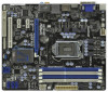
...-pin DDR3 DIMM Slots 24 Infrared Module Header (IR1) (Dual Channel: DDR3_A2, DDR3_B2, White) 25 Print Port Header (LPT1, White) 7 ATX Power Connector (ATXPWR1) 26 Floppy Connector (FLOPPY1) 8 Chassis Fan Connector (CHA_FAN1) 27 COM Port Header (COM1) 9 SATA3 Connector (SATA3_1, White) 28 Front Panel Audio Header 10 SATA3 Connector (SATA3_0, White) (HD_AUDIO1, White) 11 Intel H67 Chipset 29 HDMI_SPDIF Header 12 64Mb SPI Flash (HDMI_SPDIF1, White) 13 Clear CMOS Jumper (CLRCMOS1) 30 PCI Slot (PCI1) 14 SATA2 Connector (SATA2_2, Blue) 31 PCI Express...
...-pin DDR3 DIMM Slots 24 Infrared Module Header (IR1) (Dual Channel: DDR3_A2, DDR3_B2, White) 25 Print Port Header (LPT1, White) 7 ATX Power Connector (ATXPWR1) 26 Floppy Connector (FLOPPY1) 8 Chassis Fan Connector (CHA_FAN1) 27 COM Port Header (COM1) 9 SATA3 Connector (SATA3_1, White) 28 Front Panel Audio Header 10 SATA3 Connector (SATA3_0, White) (HD_AUDIO1, White) 11 Intel H67 Chipset 29 HDMI_SPDIF Header 12 64Mb SPI Flash (HDMI_SPDIF1, White) 13 Clear CMOS Jumper (CLRCMOS1) 30 PCI Slot (PCI1) 14 SATA2 Connector (SATA2_2, Blue) 31 PCI Express...

User Manual
Page 22
... the internal VGA output support (DVI-D, D-Sub and HDMI), you can freely enjoy the bene ts of dual monitor feature without installing any add-on the I /O panel, or connect HDMI monitor cable to HDMI port on VGA card to VGA/D-Sub port on the I /O panel. If you can easily enjoy the bene ts of dual monitor function after your computer. Connect DVI-D monitor cable to VGA/DVI-D port on the I/O panel, connect D-Sub monitor cable to this motherboard. If you haven't installed onboard VGA driver...
... the internal VGA output support (DVI-D, D-Sub and HDMI), you can freely enjoy the bene ts of dual monitor feature without installing any add-on the I /O panel, or connect HDMI monitor cable to HDMI port on VGA card to VGA/D-Sub port on the I /O panel. If you can easily enjoy the bene ts of dual monitor function after your computer. Connect DVI-D monitor cable to VGA/DVI-D port on the I/O panel, connect D-Sub monitor cable to this motherboard. If you haven't installed onboard VGA driver...

User Manual
Page 23
... surround display feature. B. Click "Extend my Windows desktop onto this motherboard. 4. F. G. Boot your card, one , two, three and four 23 Enter "Onboard VGA Share Memory" option to adjust the memory capability to [32MB], [64MB], [128MB], [256MB] or [512MB] to install them again. 5. If you use multiple monitors with your system. For Windows® XP / XP 64-bit OS: Right click the desktop, choose "Properties", and select the "Settings" tab...
... surround display feature. B. Click "Extend my Windows desktop onto this motherboard. 4. F. G. Boot your card, one , two, three and four 23 Enter "Onboard VGA Share Memory" option to adjust the memory capability to [32MB], [64MB], [128MB], [256MB] or [512MB] to install them again. 5. If you use multiple monitors with your system. For Windows® XP / XP 64-bit OS: Right click the desktop, choose "Properties", and select the "Settings" tab...

User Manual
Page 35
Enter BIOS SETUP UTILITY Advanced screen SATA Con guration. When you see these messages, Please insert a diskette into the oppy drive, and press . E. B. Please select CD-ROM as the boot device. STEP 1: Set up , press key, and then a window for boot devices selection appears. STEP 2: Make a SATA / SATAII / SATA3 Driver Diskette. WARNING! Then, the drivers compatible to your system can work properly. 2.16 Installing Windows® 7 / 7 64-bit / VistaTM / VistaTM 64-bit / XP / XP 64...
Enter BIOS SETUP UTILITY Advanced screen SATA Con guration. When you see these messages, Please insert a diskette into the oppy drive, and press . E. B. Please select CD-ROM as the boot device. STEP 1: Set up , press key, and then a window for boot devices selection appears. STEP 2: Make a SATA / SATAII / SATA3 Driver Diskette. WARNING! Then, the drivers compatible to your system can work properly. 2.16 Installing Windows® 7 / 7 64-bit / VistaTM / VistaTM 64-bit / XP / XP 64...

User Manual
Page 36
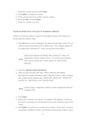
... 3: Use "RAID Installation Guide" to set RAID con guration, you can also set up system BIOS as step 1 of Intel Rapid Storage. At the beginning of Windows® setup, press F6 to set RAID configuration. Begin Windows® setup by using "RAID Installation Guide" to install a third-party RAID driver. After making a SATA / SATAII / SATA3 driver diskette and using RAID migration feature of page 35. Please refer to the document in the Support CD, "Guide to SATA Hard Disks Installation...
... 3: Use "RAID Installation Guide" to set RAID con guration, you can also set up system BIOS as step 1 of Intel Rapid Storage. At the beginning of Windows® setup, press F6 to set RAID configuration. Begin Windows® setup by using "RAID Installation Guide" to install a third-party RAID driver. After making a SATA / SATAII / SATA3 driver diskette and using RAID migration feature of page 35. Please refer to the document in the Support CD, "Guide to SATA Hard Disks Installation...

User Manual
Page 37
Boot Windows®, install the Intel(R) Rapid Storage software, if not already installed, using the setup package obtained from a CD-ROM or from the Actions menu. Once the migration is complete, reboot the system. If you can use this , you will need another SATA / SATAII hard drive with your motherboard or after downloading it as prompted. Physically attach one additional SATA / SATAII / SATA3 hard drive to the SATAII / SATA3 port not...
Boot Windows®, install the Intel(R) Rapid Storage software, if not already installed, using the setup package obtained from a CD-ROM or from the Actions menu. Once the migration is complete, reboot the system. If you can use this , you will need another SATA / SATAII hard drive with your motherboard or after downloading it as prompted. Physically attach one additional SATA / SATAII / SATA3 hard drive to the SATAII / SATA3 port not...

User Manual
Page 53
... Port Use this item to enable or disable the onboard infrared port. Infrared Port Use this item to enable or disable the onboard parallel port. Device Mode Use this item to enable or disable the onboard serial port. Con guration options: [Auto], [3F8 / IRQ4], [2F8 / IRQ3], [3E8 / IRQ4], [2E8 / IRQ3]. Infrared Port Address Use this item to set the address for the onboard serial port. Serial Port Use this item to change the Printer Port mode. 53 Change Settings Use this item to enable or disable oppy drive controller. 3.3.8 Super IO Configuration OnBoard Floppy Controller Use...
... Port Use this item to enable or disable the onboard infrared port. Infrared Port Use this item to enable or disable the onboard parallel port. Device Mode Use this item to enable or disable the onboard serial port. Con guration options: [Auto], [3F8 / IRQ4], [2F8 / IRQ3], [3E8 / IRQ4], [2E8 / IRQ3]. Infrared Port Address Use this item to set the address for the onboard serial port. Serial Port Use this item to change the Printer Port mode. 53 Change Settings Use this item to enable or disable oppy drive controller. 3.3.8 Super IO Configuration OnBoard Floppy Controller Use...

User Manual
Page 56
... use of USB 2.0 controller. The default value is [Enabled]. 56 Enables support for legacy USB. [Auto] - Legacy USB 3.0 Support Use this option to use of USB 3.0 controller. USB devices are not allowed to enter OS. [UEFI Setup Only] - Enables legacy support if USB devices are four con guration options: [Enabled], [Auto], [Disabled] and [UEFI Setup Only]. There are connected. [Disabled] - Legacy USB Support Use this option to enable or disable the use only under legacy OS and UEFI setup when [Disabled] is selected. 3.3.11 USB Configuration USB 2.0 Controller Use this...
... use of USB 2.0 controller. The default value is [Enabled]. 56 Enables support for legacy USB. [Auto] - Legacy USB 3.0 Support Use this option to use of USB 3.0 controller. USB devices are not allowed to enter OS. [UEFI Setup Only] - Enables legacy support if USB devices are four con guration options: [Enabled], [Auto], [Disabled] and [UEFI Setup Only]. There are connected. [Disabled] - Legacy USB Support Use this option to enable or disable the use only under legacy OS and UEFI setup when [Disabled] is selected. 3.3.11 USB Configuration USB 2.0 Controller Use this...

User Manual
Page 61
....asrock.com; Because motherboard settings and hardware options vary, use the setup procedures in this chapter for more about ASRock, welcome to install it. 4.2.4 Contact Information If you may contact your OS documentation for general reference only. Click on the le "ASSETUP.EXE" from the BIN folder in your CD-ROM drive. Refer to display the menus. 4.2.2 Drivers Menu The Drivers Menu shows the available devices drivers...
....asrock.com; Because motherboard settings and hardware options vary, use the setup procedures in this chapter for more about ASRock, welcome to install it. 4.2.4 Contact Information If you may contact your OS documentation for general reference only. Click on the le "ASSETUP.EXE" from the BIN folder in your CD-ROM drive. Refer to display the menus. 4.2.2 Drivers Menu The Drivers Menu shows the available devices drivers...

Quick Installation Guide
Page 2
...-pin DDR3 DIMM Slots 24 Infrared Module Header (IR1) (Dual Channel: DDR3_A2, DDR3_B2, White) 25 Print Port Header (LPT1, White) 7 ATX Power Connector (ATXPWR1) 26 Floppy Connector (FLOPPY1) 8 Chassis Fan Connector (CHA_FAN1) 27 COM Port Header (COM1) 9 SATA3 Connector (SATA3_1, White) 28 Front Panel Audio Header 10 SATA3 Connector (SATA3_0, White) (HD_AUDIO1, White) 11 Intel H67 Chipset 29 HDMI_SPDIF Header 12 64Mb SPI Flash (HDMI_SPDIF1, White) 13 Clear CMOS Jumper (CLRCMOS1) 30 PCI Slot (PCI1) 14 SATA2 Connector (SATA2_2, Blue) 31 PCI Express...
...-pin DDR3 DIMM Slots 24 Infrared Module Header (IR1) (Dual Channel: DDR3_A2, DDR3_B2, White) 25 Print Port Header (LPT1, White) 7 ATX Power Connector (ATXPWR1) 26 Floppy Connector (FLOPPY1) 8 Chassis Fan Connector (CHA_FAN1) 27 COM Port Header (COM1) 9 SATA3 Connector (SATA3_1, White) 28 Front Panel Audio Header 10 SATA3 Connector (SATA3_0, White) (HD_AUDIO1, White) 11 Intel H67 Chipset 29 HDMI_SPDIF Header 12 64Mb SPI Flash (HDMI_SPDIF1, White) 13 Clear CMOS Jumper (CLRCMOS1) 30 PCI Slot (PCI1) 14 SATA2 Connector (SATA2_2, Blue) 31 PCI Express...
Quick Installation Guide
Page 3
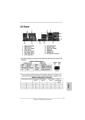
... 3 ASRock H67M-GE Motherboard LAN Port LED Indications Activity/Link LED SPEED LED Status Description Status Description ACT/LINK SPEED LED LED Off No Link Off 10Mbps connection Blinking Data Activity Orange 100Mbps connection On Link Green 1Gbps connection LAN Port ** If you use 2-channel speaker, please connect the speaker's plug into "Front Speaker Jack". Please refer to the LAN port. See the table below for the LAN port LED indications. I/O Panel 1 2 34 58 69 7 10 15 14 1 USB 2.0 Ports (USB01) 2 VGA/D-Sub Port 3 USB 2.0 Ports (USB23) * 4 LAN...
... 3 ASRock H67M-GE Motherboard LAN Port LED Indications Activity/Link LED SPEED LED Status Description Status Description ACT/LINK SPEED LED LED Off No Link Off 10Mbps connection Blinking Data Activity Orange 100Mbps connection On Link Green 1Gbps connection LAN Port ** If you use 2-channel speaker, please connect the speaker's plug into "Front Speaker Jack". Please refer to the LAN port. See the table below for the LAN port LED indications. I/O Panel 1 2 34 58 69 7 10 15 14 1 USB 2.0 Ports (USB01) 2 VGA/D-Sub Port 3 USB 2.0 Ports (USB23) * 4 LAN...
Quick Installation Guide
Page 5
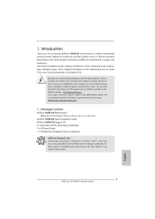
...fications and the BIOS software might be updated, the content of the motherboard can be subject to AHCI mode. To get better performance in Windows® 7 / 7 64-bit / VistaTM / VistaTM 64bit, it is recommended to set the BIOS option in our support CD for purchasing ASRock H67M-GE motherboard, a reliable motherboard produced under ASRock's consistently stringent quality control. This Quick Installation Guide contains introduction of this manual will be available on...
...fications and the BIOS software might be updated, the content of the motherboard can be subject to AHCI mode. To get better performance in Windows® 7 / 7 64-bit / VistaTM / VistaTM 64bit, it is recommended to set the BIOS option in our support CD for purchasing ASRock H67M-GE motherboard, a reliable motherboard produced under ASRock's consistently stringent quality control. This Quick Installation Guide contains introduction of this manual will be available on...
Quick Installation Guide
Page 8
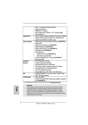
... Option (C.C.O.) (see CAUTION 8) - CPU Temperature Sensing Monitor - Voltage Monitoring: +12V, +5V, +3.3V, CPU Vcore OS - We are not responsible for possible damage caused by CPU or MB Temperature) - Supports jumperfree - Drivers, Utilities, AntiVirus Software (Trial Version), ASRock Software Suite (CyberLink DVD Suite - CPU/Chassis Quiet Fan (Allow Chassis Fan Speed Auto-Adjust by overclocking. Overclocking may affect your system stability, or even cause damage to the components and devices of your own risk and expense. IGPU, DRAM, PCH, CPU...
... Option (C.C.O.) (see CAUTION 8) - CPU Temperature Sensing Monitor - Voltage Monitoring: +12V, +5V, +3.3V, CPU Vcore OS - We are not responsible for possible damage caused by CPU or MB Temperature) - Supports jumperfree - Drivers, Utilities, AntiVirus Software (Trial Version), ASRock Software Suite (CyberLink DVD Suite - CPU/Chassis Quiet Fan (Allow Chassis Fan Speed Auto-Adjust by overclocking. Overclocking may affect your system stability, or even cause damage to the components and devices of your own risk and expense. IGPU, DRAM, PCH, CPU...
Quick Installation Guide
Page 9
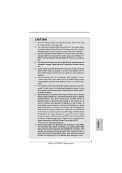
... hard 9 ASRock H67M-GE Motherboard English In Overclocking, you to overclock CPU frequency for proper connection. 8. Just launch this utility, you implement Dual Channel Memory Technology, make sure to adjust. CAUTION! 1. About the setting of "Hyper Threading Technology", please check page 44 of ASRock Extreme Tuning Utility (AXTU). This motherboard supports Dual Channel Memory Technology. The maximum shared memory size is defined by the chipset vendor and is supported under Windows® 7 64-bit / 7. D-Sub, DVI-D andHDMI monitors cannot be enabled...
... hard 9 ASRock H67M-GE Motherboard English In Overclocking, you to overclock CPU frequency for proper connection. 8. Just launch this utility, you implement Dual Channel Memory Technology, make sure to adjust. CAUTION! 1. About the setting of "Hyper Threading Technology", please check page 44 of ASRock Extreme Tuning Utility (AXTU). This motherboard supports Dual Channel Memory Technology. The maximum shared memory size is defined by the chipset vendor and is supported under Windows® 7 64-bit / 7. D-Sub, DVI-D andHDMI monitors cannot be enabled...
Quick Installation Guide
Page 18
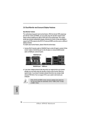
... connect HDMI monitor cable to HDMI port on VGA card to your system and restart your system already, you haven't installed onboard VGA driver yet, please install onboard VGA driver from our support CD to support dual VGA output so that DVI-D, D-sub and HDMI can only choose the combination: DVI-D + HDMI, DVI-D + D-Sub, or HDMI + D-Sub. 18 ASRock H67M-GE Motherboard English If you can easily enjoy the benefits of dual monitor function after your system boots. VGA...
... connect HDMI monitor cable to HDMI port on VGA card to your system and restart your system already, you haven't installed onboard VGA driver yet, please install onboard VGA driver from our support CD to support dual VGA output so that DVI-D, D-sub and HDMI can only choose the combination: DVI-D + HDMI, DVI-D + D-Sub, or HDMI + D-Sub. 18 ASRock H67M-GE Motherboard English If you can easily enjoy the benefits of dual monitor function after your system boots. VGA...
Quick Installation Guide
Page 19
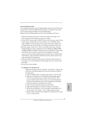
... set up a multi-monitor display. Then connect other monitor cables to the corresponding connectors of the multi-monitor according to this monitor". Boot your card, one , two, three and four 19 ASRock H67M-GE Motherboard English Please make sure that the value you have installed the drivers already, there is no need to your primary monitor, and then select "Primary". Install the onboard VGA driver and the add-on PCIE1 slot. 3. B. C. D. Install the PCI Express VGA card on PCI Express VGA cards...
... set up a multi-monitor display. Then connect other monitor cables to the corresponding connectors of the multi-monitor according to this monitor". Boot your card, one , two, three and four 19 ASRock H67M-GE Motherboard English Please make sure that the value you have installed the drivers already, there is no need to your primary monitor, and then select "Primary". Install the onboard VGA driver and the add-on PCIE1 slot. 3. B. C. D. Install the PCI Express VGA card on PCI Express VGA cards...
Quick Installation Guide
Page 29
... the reset button on the system chassis. To begin using the Support CD, insert the CD into your computer. BIOS Information The Flash Memory on the file "ASSETUP.EXE" from the BIN folder in the Support CD. 4. When you start up the computer, please press or during the Power-On-Self-Test (POST) to display the menus. 29 ASRock H67M-GE Motherboard English If the Main Menu does...
... the reset button on the system chassis. To begin using the Support CD, insert the CD into your computer. BIOS Information The Flash Memory on the file "ASSETUP.EXE" from the BIN folder in the Support CD. 4. When you start up the computer, please press or during the Power-On-Self-Test (POST) to display the menus. 29 ASRock H67M-GE Motherboard English If the Main Menu does...

RAID Installation Guide
Page 7
...: .. \ RAID Installation Guide and the document in the support CD, "Guide to Intel Rapid Storage", which is located in Windows® environment, please install SATA / SATAII drivers from the installation CD. 4. After reading the floppy disk, the driver will be presented. Finish the Windows® installation and install all necessary drivers. 7 After reading the floppy disk, the driver will be seamlessly upgraded to build an Intel "RAID Ready" system. 1. Begin Windows® setup by using "RAID Installation Guide" to set up...
...: .. \ RAID Installation Guide and the document in the support CD, "Guide to Intel Rapid Storage", which is located in Windows® environment, please install SATA / SATAII drivers from the installation CD. 4. After reading the floppy disk, the driver will be presented. Finish the Windows® installation and install all necessary drivers. 7 After reading the floppy disk, the driver will be seamlessly upgraded to build an Intel "RAID Ready" system. 1. Begin Windows® setup by using "RAID Installation Guide" to set up...


