User Manual
Page 3
...Power Menu 27 4. Boot Menu 28 5. Contents 1 Introduction 4 1.1 Package Contents 4 1.2 Specifications 5 1.3 Motherboard Layout 7 1.4 ASRock I/OTM 8 2 Installation 9 2.1 Screw Holes 9 2.2 Pre-installation Precautions 9 2.3 CPU Installation 10 2.4 Installation of Heatsink and CPU fan 10 2.5 Installation of Memory Modules (DIMM 11 2.6 Expansion Slots 11 2.7 Jumpers Setup 12 2.8 Connectors 15 3 BIOS Setup 17 3.1 BIOS Setup Utility 17 3.1.1 BIOS Menu Bar 17 3.1.2 Legend Bar 17 3.2 Main Menu 18 3.3 Advanced, Security, Power, Boot, and Exit Menus ...... 20 4 Software Support...
...Power Menu 27 4. Boot Menu 28 5. Contents 1 Introduction 4 1.1 Package Contents 4 1.2 Specifications 5 1.3 Motherboard Layout 7 1.4 ASRock I/OTM 8 2 Installation 9 2.1 Screw Holes 9 2.2 Pre-installation Precautions 9 2.3 CPU Installation 10 2.4 Installation of Heatsink and CPU fan 10 2.5 Installation of Memory Modules (DIMM 11 2.6 Expansion Slots 11 2.7 Jumpers Setup 12 2.8 Connectors 15 3 BIOS Setup 17 3.1 BIOS Setup Utility 17 3.1.1 BIOS Menu Bar 17 3.1.2 Legend Bar 17 3.2 Main Menu 18 3.3 Advanced, Security, Power, Boot, and Exit Menus ...... 20 4 Software Support...
User Manual
Page 4
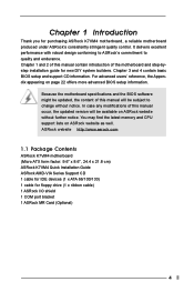
... basic BIOS setup and support CD information. Chapter 1 and 2 of the motherboard and step-bystep installation guide for floppy drive (1 x ribbon cable) 1 ASRock I/O shield 1 COM port bracket 1 ASRock MR Card (Optional) 4 Because the motherboard specifications and the BIOS software might be updated, the content of this manual contain introduction of this manual will be subject to quality and endurance. Chapter 1 Introduction Thank you for purchasing ASRock K7VM4 motherboard, a reliable motherboard produced under ASRock's consistently stringent quality control.
... basic BIOS setup and support CD information. Chapter 1 and 2 of the motherboard and step-bystep installation guide for floppy drive (1 x ribbon cable) 1 ASRock I/O shield 1 COM port bracket 1 ASRock MR Card (Optional) 4 Because the motherboard specifications and the BIOS software might be updated, the content of this manual contain introduction of this manual will be subject to quality and endurance. Chapter 1 Introduction Thank you for purchasing ASRock K7VM4 motherboard, a reliable motherboard produced under ASRock's consistently stringent quality control.

User Manual
Page 5
...VGA: VIA UniChrome Graphics, Max. 64MB VRAM Memory: 2 DDR DIMM slots: DDR1 and DDR2 PC2700 (DDR333) / PC2100 (DDR266) / PC1600 (DDR200), Max. 2GB (see CAUTION 2); CPU overheat shutdown to 4 IDE devices Floppy Port: Supports 2 floppy disk drives Audio: 5.1 channels AC'97 Audio LAN: Speed: 802.3u (10/100 Ethernet), supports Wake-On-LAN Hardware Monitor: CPU temperature sensing; Audio Jack: Line Out / Line In / Microphone + Game port BIOS: AMI legal BIOS; Voltage monitoring: +12V, +5V, +3V, Vcore; CPU frequency stepless control (only for two ASRock I/OTM: additional USB...
...VGA: VIA UniChrome Graphics, Max. 64MB VRAM Memory: 2 DDR DIMM slots: DDR1 and DDR2 PC2700 (DDR333) / PC2100 (DDR266) / PC1600 (DDR200), Max. 2GB (see CAUTION 2); CPU overheat shutdown to 4 IDE devices Floppy Port: Supports 2 floppy disk drives Audio: 5.1 channels AC'97 Audio LAN: Speed: 802.3u (10/100 Ethernet), supports Wake-On-LAN Hardware Monitor: CPU temperature sensing; Audio Jack: Line Out / Line In / Microphone + Game port BIOS: AMI legal BIOS; Voltage monitoring: +12V, +5V, +3V, Vcore; CPU frequency stepless control (only for two ASRock I/OTM: additional USB...
User Manual
Page 6
... as PCI clock, AGP clock, and Memory clock will automatically shutdown. It may not work properly under Microsoft® Windows® XP. Please refer to spray thermal grease between the CPU and the heatsink when you resume the system. When the CPU frequency of K7VM4 motherboard! PC1600 (DDR200) is detected, the system will also be overclocked proportionally. While CPU overheat is supported ONLY when using FSB200 (Duron) processor...
... as PCI clock, AGP clock, and Memory clock will automatically shutdown. It may not work properly under Microsoft® Windows® XP. Please refer to spray thermal grease between the CPU and the heatsink when you resume the system. When the CPU frequency of K7VM4 motherboard! PC1600 (DDR200) is detected, the system will also be overclocked proportionally. While CPU overheat is supported ONLY when using FSB200 (Duron) processor...
User Manual
Page 7
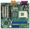
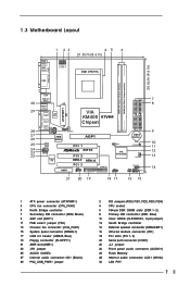
...) 13 Chassis fan connector (CHA_FAN1) 15 System panel connector (PANEL1) 17 USB 2.0 header (USB45, Blue) 19 Floppy connector (FLOPPY1) 21 AMR slot (AMR1) 23 JR1 jumper 25 AUDIO CODEC 27 Internal audio connector: CD1 (Black) 29 PS2_USB_PWR1 jumper 2 FID Jumpers (FID0, FID1, FID2, FID3, FID4) 4 CPU socket 6 184-pin DDR DIMM slots (DDR 1- 2) 8 Primary IDE connector (IDE1, Blue) 10 Clear CMOS (CLRCMOS1, 2-pin jumper) 12 South Bridge controller 14 External speaker connector (SPEAKER 1) 16 Infrared module connector (IR1) 18 PCI slots (PCI 1- 3) 20 Serial port connector (COM1...
...) 13 Chassis fan connector (CHA_FAN1) 15 System panel connector (PANEL1) 17 USB 2.0 header (USB45, Blue) 19 Floppy connector (FLOPPY1) 21 AMR slot (AMR1) 23 JR1 jumper 25 AUDIO CODEC 27 Internal audio connector: CD1 (Black) 29 PS2_USB_PWR1 jumper 2 FID Jumpers (FID0, FID1, FID2, FID3, FID4) 4 CPU socket 6 184-pin DDR DIMM slots (DDR 1- 2) 8 Primary IDE connector (IDE1, Blue) 10 Clear CMOS (CLRCMOS1, 2-pin jumper) 12 South Bridge controller 14 External speaker connector (SPEAKER 1) 16 Infrared module connector (IR1) 18 PCI slots (PCI 1- 3) 20 Serial port connector (COM1...

User Manual
Page 9
... electricity, NEVER place your chassis to you uninstall any motherboard settings. 1. Also remember to do not touch the ICs. 4. Before you install the motherboard, study the configuration of the following precautions before you handle components. 3. Failure to use a grounded wrist strap or touch a safety grounded object before you install motherboard components or change any component, place it . Failure to do so may...
... electricity, NEVER place your chassis to you uninstall any motherboard settings. 1. Also remember to do not touch the ICs. 4. Before you install the motherboard, study the configuration of the following precautions before you handle components. 3. Failure to use a grounded wrist strap or touch a safety grounded object before you install motherboard components or change any component, place it . Failure to do so may...

User Manual
Page 15
...) Internal audio connectors (4-pin CD1, 4-pin AUX1) (CD1: see p.7 item 27) (AUX1: see p.7 item 7) PIN1 IDE1 PIN1 IDE2 connect the blue end connect the black end to the motherboard to the IDE devices 80-Pin ATA 100/133 cable Note: To optimize compatibility and performance, please connect your hard disk drive to the primary IDE connector (IDE1, blue) and CD-ROM to receive stereo audio input from sound sources such as a CD-ROM, DVD-ROM...
...) Internal audio connectors (4-pin CD1, 4-pin AUX1) (CD1: see p.7 item 27) (AUX1: see p.7 item 7) PIN1 IDE1 PIN1 IDE2 connect the blue end connect the black end to the motherboard to the IDE devices 80-Pin ATA 100/133 cable Note: To optimize compatibility and performance, please connect your hard disk drive to the primary IDE connector (IDE1, blue) and CD-ROM to receive stereo audio input from sound sources such as a CD-ROM, DVD-ROM...

User Manual
Page 16
... panel audio cable that allows convenient connection and control of audio devices. CHA_FAN_SPEED +12V GND Connect the fan cable to the connector matching the black wire to an external speaker. L GND A U D - Serial port connector (9-pin COM1) (see p.7 item 1) Connect an ATX power supply to the connector. O U T- This connector allows you to attach to the ground pin. O U T- ATX power connector (20-pin ATXPWR1) (see p.7 item 20) RRXD1 DDTR#1 DDSR#1 CCTS#1 1 RRI#1 RRTS#1 GND TTXD1 DDCD#1 This COM1 header supports a serial port module. 16 CPU fan connector (3-pin...
... panel audio cable that allows convenient connection and control of audio devices. CHA_FAN_SPEED +12V GND Connect the fan cable to the connector matching the black wire to an external speaker. L GND A U D - Serial port connector (9-pin COM1) (see p.7 item 1) Connect an ATX power supply to the connector. O U T- This connector allows you to attach to the ground pin. O U T- ATX power connector (20-pin ATXPWR1) (see p.7 item 20) RRXD1 DDTR#1 DDSR#1 CCTS#1 1 RRI#1 RRTS#1 GND TTXD1 DDCD#1 This COM1 header supports a serial port module. 16 CPU fan connector (3-pin...
User Manual
Page 17
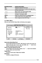
... BIOS Setup Utility to configure your screen. 3.1.1 BIOS Menu Bar The top of the screen has a menu bar with the following selections: MAIN Sets up the basic system configuration ADVANCED Sets up the advanced features SECURITY Sets up the computer. If you start up the security features POWER Configures Power Management features BOOT Configures the default system device that is used to locate and load the Operating System EXIT Exits the current menu or the BIOS Setup To access...
... BIOS Setup Utility to configure your screen. 3.1.1 BIOS Menu Bar The top of the screen has a menu bar with the following selections: MAIN Sets up the basic system configuration ADVANCED Sets up the advanced features SECURITY Sets up the computer. If you start up the security features POWER Configures Power Management features BOOT Configures the default system device that is used to locate and load the Operating System EXIT Exits the current menu or the BIOS Setup To access...
User Manual
Page 18
IDE Devices Use this to set the type of floppy drives installed. Valid values for month, day, and year are Month: (Jan to Dec), Day: (1 to 31), Year: (up a selected menu for a highlighted field Loads all setup items to the default values Saves changes and exits BIOS Setup 3.2 Main Menu When you enter the BIOS Setup Utility, the following screen appears. Floppy Drives Use this to configure IDE devices. 18 Navigation Key(s) / / + / Function Description Displays the General Help Screen Jumps to the...
IDE Devices Use this to set the type of floppy drives installed. Valid values for month, day, and year are Month: (Jan to Dec), Day: (1 to 31), Year: (up a selected menu for a highlighted field Loads all setup items to the default values Saves changes and exits BIOS Setup 3.2 Main Menu When you enter the BIOS Setup Utility, the following screen appears. Floppy Drives Use this to configure IDE devices. 18 Navigation Key(s) / / + / Function Description Displays the General Help Screen Jumps to the...

User Manual
Page 20
..., Power, Boot, and Exit Menus Detailed descriptions of these menus are listed in the Appendix. Sectors This is used to configure the number of cylinders. Refer to the drive documentation to maximize the IDE hard disk data transfer rate. Fast Programmed I/O Modes This allows user to set the PIO mode to enhance hard disk performance by optimizing the hard disk timing. 32 Bit Transfer Mode It allows user to enable 32-bit access...
..., Power, Boot, and Exit Menus Detailed descriptions of these menus are listed in the Appendix. Sectors This is used to configure the number of cylinders. Refer to the drive documentation to maximize the IDE hard disk data transfer rate. Fast Programmed I/O Modes This allows user to set the PIO mode to enhance hard disk performance by optimizing the hard disk timing. 32 Bit Transfer Mode It allows user to enable 32-bit access...
User Manual
Page 21
... motherboard settings and hardware options vary, use the setup procedures in your computer. Refer to display the menus. 4.2.2 Drivers Menu The Drivers Menu shows the available devices drivers if the system detects installed devices. Click on the file ASSETUP.EXE from the BIN folder in the Support CD to your CD-ROM drive. or you may contact your own PC system step by step. Chapter 4 Software Support 4.1 Install Operating System This motherboard supports...
... motherboard settings and hardware options vary, use the setup procedures in your computer. Refer to display the menus. 4.2.2 Drivers Menu The Drivers Menu shows the available devices drivers if the system detects installed devices. Click on the file ASSETUP.EXE from the BIN folder in the Support CD to your CD-ROM drive. or you may contact your own PC system step by step. Chapter 4 Software Support 4.1 Install Operating System This motherboard supports...
User Manual
Page 22
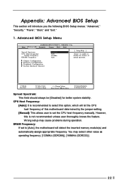
... Monitor F1:Help Esc:Exit :Select Item :Select Menu +/-:Change Values Enter:Select Sub-Menu F9:Setup Defaults F10:Save & Exit Spread Spectrum: This field should always be [Disabled] for better system stability. VERSION 3.31a Security Power Boot Exit Spread Spectrum CPU Host Frequency Actual Frequency DRAM Frequency Disabled Auto 166MHz Auto [ Setup Help ] to select this option, which will let the CPU host frequency of spread spectrum. However, this motherboard determined by the jumper-setting. [Manual...
... Monitor F1:Help Esc:Exit :Select Item :Select Menu +/-:Change Values Enter:Select Sub-Menu F9:Setup Defaults F10:Save & Exit Spread Spectrum: This field should always be [Disabled] for better system stability. VERSION 3.31a Security Power Boot Exit Spread Spectrum CPU Host Frequency Actual Frequency DRAM Frequency Disabled Auto 166MHz Auto [ Setup Help ] to select this option, which will let the CPU host frequency of spread spectrum. However, this motherboard determined by the jumper-setting. [Manual...
User Manual
Page 23
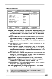
...is used for graphics memory. DRAM CAS# Latency: This is recommended to [Auto] automatically. Chipset Configuration: Advanced AMIBIOS SETUP UTILITY - VERSION 3.31a Chipset Configuration [ Setup Help ] AGP Mode AGP Aperture Size AGP Fast Write Onboard VGA Share Memory PCI Delay Transaction USB Controller USB Device Legacy Support DRAM CAS# Latency Over Vcore Voltage Auto 128MB Disabled Auto Disabled Enabled Disabled Auto Disabled to emulate legacy I/O devices such as the default value. If the installed AGP card is [Disabled]. Onboard VGA will free the PCI Bus when the CPU...
...is used for graphics memory. DRAM CAS# Latency: This is recommended to [Auto] automatically. Chipset Configuration: Advanced AMIBIOS SETUP UTILITY - VERSION 3.31a Chipset Configuration [ Setup Help ] AGP Mode AGP Aperture Size AGP Fast Write Onboard VGA Share Memory PCI Delay Transaction USB Controller USB Device Legacy Support DRAM CAS# Latency Over Vcore Voltage Auto 128MB Disabled Auto Disabled Enabled Disabled Auto Disabled to emulate legacy I/O devices such as the default value. If the installed AGP card is [Disabled]. Onboard VGA will free the PCI Bus when the CPU...

User Manual
Page 24
... (PCI Clocks) 32 Primary Graphics Adapter PCI to enable or disable the floppy drive controller. Peripheral Configuration: Advanced AMIBIOS SETUP UTILITY - OnBoard Infrared Port: You may select [Auto] or [Disabled] for this to enable or disable floppy drive controller. F1:Help Esc:Previous Menu :Select Item +/-:Change Values Enter:Select Sub-Menu F9:Setup Defaults F10:Save & Exit OnBoard FDC: Use this onboard infrared port feature. 24 It is 32. VERSION 3.31a Peripheral Configuration [ Setup Help ] OnBoard FDC OnBoard Serial Port OnBoard Infrared Port OnBoard...
... (PCI Clocks) 32 Primary Graphics Adapter PCI to enable or disable the floppy drive controller. Peripheral Configuration: Advanced AMIBIOS SETUP UTILITY - OnBoard Infrared Port: You may select [Auto] or [Disabled] for this to enable or disable floppy drive controller. F1:Help Esc:Previous Menu :Select Item +/-:Change Values Enter:Select Sub-Menu F9:Setup Defaults F10:Save & Exit OnBoard FDC: Use this onboard infrared port feature. 24 It is 32. VERSION 3.31a Peripheral Configuration [ Setup Help ] OnBoard FDC OnBoard Serial Port OnBoard Infrared Port OnBoard...

User Manual
Page 25
...primary IDE channel or the secondary IDE channel. VERSION 3.31a System Hardware Monitor [ Setup Help ] CPU Temperature M / B Temperature CPU FAN Speed Chassis FAN Speed Vcore + 3.30V + 5.00V + 12.00V 35 C / 95 F 27 C / 82 F 3110 RPM 0 RPM 1.72 V 3.31 V 4.97 V 12.16 V F1:Help Esc:Previous Menu :Select Item +/-:Change Values Enter:Select Sub-Menu F9:Setup Defaults F10:Save & Exit 25 Configuration options: [Disabled], [Primary], [Secondary], [Both]. Configuration options: [Auto], [Disabled], [378], [278]. Advanced AMIBIOS SETUP UTILITY - OnBoard Parallel Port: Select...
...primary IDE channel or the secondary IDE channel. VERSION 3.31a System Hardware Monitor [ Setup Help ] CPU Temperature M / B Temperature CPU FAN Speed Chassis FAN Speed Vcore + 3.30V + 5.00V + 12.00V 35 C / 95 F 27 C / 82 F 3110 RPM 0 RPM 1.72 V 3.31 V 4.97 V 12.16 V F1:Help Esc:Previous Menu :Select Item +/-:Change Values Enter:Select Sub-Menu F9:Setup Defaults F10:Save & Exit 25 Configuration options: [Disabled], [Primary], [Secondary], [Both]. Configuration options: [Auto], [Disabled], [378], [278]. Advanced AMIBIOS SETUP UTILITY - OnBoard Parallel Port: Select...

User Manual
Page 26
...create a new password. Security Setup Menu Main Advanced AMIBIOS SETUP UTILITY - If you already have a password, you must enter your current password first in order to set User Password. If you already have a password, you must enter your current password first in order to 6 alphanumeric characters combination. VERSION 3.31a Security Power Boot Exit Supervisor Password User Password Set Supervisor Password Set User Password Clear Clear [ Enter ] [ Enter ] [ Setup Help ] to create a new p assword. Configuration options: [Setup], [Always]. If [Always] option is selected...
...create a new password. Security Setup Menu Main Advanced AMIBIOS SETUP UTILITY - If you already have a password, you must enter your current password first in order to set User Password. If you already have a password, you must enter your current password first in order to 6 alphanumeric characters combination. VERSION 3.31a Security Power Boot Exit Supervisor Password User Password Set Supervisor Password Set User Password Clear Clear [ Enter ] [ Enter ] [ Setup Help ] to create a new p assword. Configuration options: [Setup], [Always]. If [Always] option is selected...

User Manual
Page 27
3. PCI Devices Power On: Use this to enable or disable PS/2 keyboard to turn on the system from the power-soft-off mode. If [Enable] is recommended to enable this to enable or disable RTC (Real Time Clock) to boot up time you to -RAM feature. Repost Video on STR resume. RTC Alarm Power On: Use this feature under Microsoft® Windows® 98 / ME. VERSION 3.31a Security Power Boot Exit Suspend To RAM Repost Video on...
3. PCI Devices Power On: Use this to enable or disable PS/2 keyboard to turn on the system from the power-soft-off mode. If [Enable] is recommended to enable this to enable or disable RTC (Real Time Clock) to boot up time you to -RAM feature. Repost Video on STR resume. RTC Alarm Power On: Use this feature under Microsoft® Windows® 98 / ME. VERSION 3.31a Security Power Boot Exit Suspend To RAM Repost Video on...

User Manual
Page 28
... No Disabled [ Setup Help ] to set the boot device priority. 28 Boot From Network: Use this mode will automatically activate the Numeric Lock function after boot-up to enable or disable "boot from network" feature. Boot Setup Menu Main Advanced AMIBIOS SETUP UTILITY - 4. Boot Up Num-Lock: If this is enabled, it will speed up the boot-up routine by skipping memory retestings. Boot Device Priority F1:Help Esc:Exit :Select Item :Select Menu +/-:Change Values Enter:Select Sub-Menu F9:Setup Defaults...
... No Disabled [ Setup Help ] to set the boot device priority. 28 Boot From Network: Use this mode will automatically activate the Numeric Lock function after boot-up to enable or disable "boot from network" feature. Boot Setup Menu Main Advanced AMIBIOS SETUP UTILITY - 4. Boot Up Num-Lock: If this is enabled, it will speed up the boot-up routine by skipping memory retestings. Boot Device Priority F1:Help Esc:Exit :Select Item :Select Menu +/-:Change Values Enter:Select Sub-Menu F9:Setup Defaults...
User Manual
Page 29
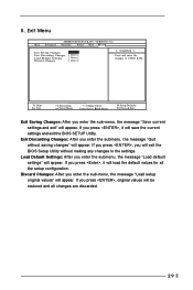
VERSION 3.31a Security Power Boot Exit Exit Saving Changes Exit Discarding Changes Load Default Settings Discard Changes [ Enter ] [ Enter ] [ Enter ] [ Enter ] [ Setup Help ] Exits and saves the changes to the settings. If you press , original values will be restored and all the setup configuration. Exit Menu Main Advanced AMIBIOS SETUP UTILITY - 5. If you press , it will save the current settings and exit the BIOS SETUP Utility. If you press , you press , it will load the default values for all...
VERSION 3.31a Security Power Boot Exit Exit Saving Changes Exit Discarding Changes Load Default Settings Discard Changes [ Enter ] [ Enter ] [ Enter ] [ Enter ] [ Setup Help ] Exits and saves the changes to the settings. If you press , original values will be restored and all the setup configuration. Exit Menu Main Advanced AMIBIOS SETUP UTILITY - 5. If you press , it will save the current settings and exit the BIOS SETUP Utility. If you press , you press , it will load the default values for all...


