User Manual
Page 3
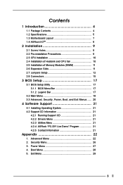
...26 3. Boot Menu 28 5. Exit Menu 29 3 Advanced Menu 22 2. Power Menu 27 4. Contents 1 Introduction 4 1.1 Package Contents 4 1.2 Specifications 5 1.3 Motherboard Layout 7 1.4 ASRock I/OTM 8 2 Installation 9 2.1 Screw Holes 9 2.2 Pre-installation Precautions 9 2.3 CPU Installation 10 2.4 Installation of Heatsink and CPU fan 10 2.5 Installation of ... Installing Operating System 21 4.2 Support CD Information 21 4.2.1 Running Support CD 21 4.2.2 Drivers Menu 21 4.2.3 Utilities Menu 21 4.2.4 ASRock "PC-DIY Live Demo" Program 21 4.2.5 Contact Information 21 Appendix 22 1.
...26 3. Boot Menu 28 5. Exit Menu 29 3 Advanced Menu 22 2. Power Menu 27 4. Contents 1 Introduction 4 1.1 Package Contents 4 1.2 Specifications 5 1.3 Motherboard Layout 7 1.4 ASRock I/OTM 8 2 Installation 9 2.1 Screw Holes 9 2.2 Pre-installation Precautions 9 2.3 CPU Installation 10 2.4 Installation of Heatsink and CPU fan 10 2.5 Installation of ... Installing Operating System 21 4.2 Support CD Information 21 4.2.1 Running Support CD 21 4.2.2 Drivers Menu 21 4.2.3 Utilities Menu 21 4.2.4 ASRock "PC-DIY Live Demo" Program 21 4.2.5 Contact Information 21 Appendix 22 1.
User Manual
Page 4
...-bystep installation guide for new DIY system builders. ASRock website http://www.asrock.com 1.1 Package Contents ASRock K7VM4 motherboard (Micro ATX form factor: 9.6" x 8.6", 24.4 x 21.8 cm) ASRock K7VM4 Quick Installation Guide ASRock AMD-VIA Series Support CD 1 cable for IDE devices (1 x ATA 66/100/133) 1 cable for purchasing ASRock K7VM4 motherboard, a reliable motherboard produced under ASRock's consistently stringent quality control. It delivers excellent...
...-bystep installation guide for new DIY system builders. ASRock website http://www.asrock.com 1.1 Package Contents ASRock K7VM4 motherboard (Micro ATX form factor: 9.6" x 8.6", 24.4 x 21.8 cm) ASRock K7VM4 Quick Installation Guide ASRock AMD-VIA Series Support CD 1 cable for IDE devices (1 x ATA 66/100/133) 1 cable for purchasing ASRock K7VM4 motherboard, a reliable motherboard produced under ASRock's consistently stringent quality control. It delivers excellent...
User Manual
Page 6
... refer to perform over clocking, other than the recommended CPU bus frequencies may cause the instability of K7VM4 motherboard! While CPU overheat is supported ONLY when using FSB200 (Duron) processor. 2. Although K7VM4 offers stepless control, it is set to spray thermal grease between the CPU and the heatsink when you...It may not work properly under Microsoft® Windows® XP. It may cause permanent damage! 4. When the CPU frequency of K7VM4 is not recommended to Microsoft® official document at http://www.microsoft.com/whdc/hwdev/bus/USB/USB2support.mspx 5.
... refer to perform over clocking, other than the recommended CPU bus frequencies may cause the instability of K7VM4 motherboard! While CPU overheat is supported ONLY when using FSB200 (Duron) processor. 2. Although K7VM4 offers stepless control, it is set to spray thermal grease between the CPU and the heatsink when you...It may not work properly under Microsoft® Windows® XP. It may cause permanent damage! 4. When the CPU frequency of K7VM4 is not recommended to Microsoft® official document at http://www.microsoft.com/whdc/hwdev/bus/USB/USB2support.mspx 5.
User Manual
Page 7
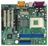
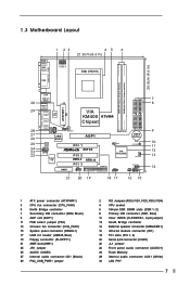
1.3 Motherboard Layout DDR1 (64/72 bit, 184-pin module) DDR2 (64/72 bit, 184-pin module) 24.4cm (9.6 in) PARALLEL PORT FID0 1 FID1 1 FID2 1 FID3 1 FID4 1 ... 25 24 23 22 LAN USB 2.0 Ports USB 2.0 Ports GGAAMMEE AAUUDDIIOO11 ATXPWR1 Line out LiLInnineein MMIniicc in LAN PHY 1 PS2_USB_PWR1 CPU_FAN1 2MB BIOS VIA KM400 K7VM4 Chipset AGP1 01 23 IDE2 IDE1 CMOS Battery AUDIO CODEC AUDIO1 1 JR1 JL1 Super I/O AMR1 PCI 1 AGP 8X PCI 2 USB2.0 PCI 3 COM1 1 ATA133 FLOPPY1 1 FS0...
1.3 Motherboard Layout DDR1 (64/72 bit, 184-pin module) DDR2 (64/72 bit, 184-pin module) 24.4cm (9.6 in) PARALLEL PORT FID0 1 FID1 1 FID2 1 FID3 1 FID4 1 ... 25 24 23 22 LAN USB 2.0 Ports USB 2.0 Ports GGAAMMEE AAUUDDIIOO11 ATXPWR1 Line out LiLInnineein MMIniicc in LAN PHY 1 PS2_USB_PWR1 CPU_FAN1 2MB BIOS VIA KM400 K7VM4 Chipset AGP1 01 23 IDE2 IDE1 CMOS Battery AUDIO CODEC AUDIO1 1 JR1 JL1 Super I/O AMR1 PCI 1 AGP 8X PCI 2 USB2.0 PCI 3 COM1 1 ATA133 FLOPPY1 1 FS0...

User Manual
Page 9
... may cause severe damage to use a grounded wrist strap or touch a safety grounded object before you install motherboard components or change any component. 2. Chapter 2 Installation K7VM4 is detached from the wall socket before touching any motherboard settings. 1. Before you uninstall any component, place it . Before you and damages to the chassis. Hold components...
... may cause severe damage to use a grounded wrist strap or touch a safety grounded object before you install motherboard components or change any component. 2. Chapter 2 Installation K7VM4 is detached from the wall socket before touching any motherboard settings. 1. Before you uninstall any component, place it . Before you and damages to the chassis. Hold components...

User Manual
Page 11
...Step 2. Keep the screws for the card. AGP slot: The AGP slot is completely seated on the slot such that you intend to insert an ASRock MR card (optional) with v.92 Modem functionality. Do NOT insert a 3.3V AGP card into the slot until the card is used to the ... a graphics card. Step 1. Installing an expansion card Step 1. Remove the bracket facing the slot that the notch on the DIMM matches the break on K7VM4 motherboard. AMR slot: AMR slot is properly seated. 2.6 Expansion Slots (PCI, AMR, and AGP Slots) There are used to disconnect power supply before adding ...
...Step 2. Keep the screws for the card. AGP slot: The AGP slot is completely seated on the slot such that you intend to insert an ASRock MR card (optional) with v.92 Modem functionality. Do NOT insert a 3.3V AGP card into the slot until the card is used to the ... a graphics card. Step 1. Installing an expansion card Step 1. Remove the bracket facing the slot that the notch on the DIMM matches the break on K7VM4 motherboard. AMR slot: AMR slot is properly seated. 2.6 Expansion Slots (PCI, AMR, and AGP Slots) There are used to disconnect power supply before adding ...
User Manual
Page 12
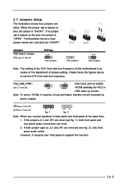
... panel to set the CPU front side bus frequency. However, it requires 2 Amp and higher standby current provided by means of the adjustment of this motherboard is by power supply. If both front panel and rear panel audio connectors can work. 2. If no jumper cap is placed on JL1 and JR1...
... panel to set the CPU front side bus frequency. However, it requires 2 Amp and higher standby current provided by means of the adjustment of this motherboard is by power supply. If both front panel and rear panel audio connectors can work. 2. If no jumper cap is placed on JL1 and JR1...

User Manual
Page 15
... FDD connector (33-pin FLOPPY1) (see p.7 item 7) PIN1 IDE1 PIN1 IDE2 connect the blue end connect the black end to the motherboard to the IDE devices 80-Pin ATA 100/133 cable Note: To optimize compatibility and performance, please connect your hard disk drive to the...item 16) Internal audio connectors (4-pin CD1, 4-pin AUX1) (CD1: see p.7 item 27) (AUX1: see p.7 item 17) USB_PWR P-5 P+5 GND DUMMY 1 GND P+4 P-4 USB_PWR ASRock I/OTM provides 4 default USB 2.0 ports on the rear panel are NOT jumpers. DO NOT place jumper caps over these connectors. If those 4 USB 2.0 ports on...
... FDD connector (33-pin FLOPPY1) (see p.7 item 7) PIN1 IDE1 PIN1 IDE2 connect the blue end connect the black end to the motherboard to the IDE devices 80-Pin ATA 100/133 cable Note: To optimize compatibility and performance, please connect your hard disk drive to the...item 16) Internal audio connectors (4-pin CD1, 4-pin AUX1) (CD1: see p.7 item 27) (AUX1: see p.7 item 17) USB_PWR P-5 P+5 GND DUMMY 1 GND P+4 P-4 USB_PWR ASRock I/OTM provides 4 default USB 2.0 ports on the rear panel are NOT jumpers. DO NOT place jumper caps over these connectors. If those 4 USB 2.0 ports on...
User Manual
Page 17
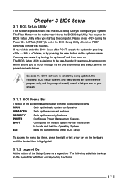
... is designed to enter the BIOS Setup after POST, restart the system by pressing + + , or by turning the system off and then back on the motherboard stores the BIOS Setup Utility. The BIOS Setup Utility is a menu-driven program, which allows you wish to be user-friendly.
... is designed to enter the BIOS Setup after POST, restart the system by pressing + + , or by turning the system off and then back on the motherboard stores the BIOS Setup Utility. The BIOS Setup Utility is a menu-driven program, which allows you wish to be user-friendly.
User Manual
Page 21
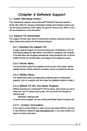
... information. 4.2 Support CD Information The Support CD that came with the motherboard contains necessary drivers and useful utilities that the motherboard supports. Because motherboard settings and hardware options vary, use the setup procedures in the Support CD to visit ASRock's website at http://www.asrock.com; Refer to activate the devices. 4.2.3 Utilities Menu The Utilities...
... information. 4.2 Support CD Information The Support CD that came with the motherboard contains necessary drivers and useful utilities that the motherboard supports. Because motherboard settings and hardware options vary, use the setup procedures in the Support CD to visit ASRock's website at http://www.asrock.com; Refer to activate the devices. 4.2.3 Utilities Menu The Utilities...
User Manual
Page 22
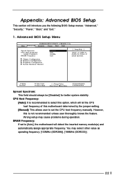
... Power Boot Exit Spread Spectrum CPU Host Frequency Actual Frequency DRAM Frequency Disabled Auto 166MHz Auto [ Setup Help ] to set to [Auto], the motherboard will introduce you the following BIOS Setup menus: "Advanced," "Security," "Power," "Boot," and "Exit." 1. Wrong setup may select other value...(DDR266)], [166MHz (DDR333)]. 22 However, this is recommended to select this option, which will let the CPU host frequency of this motherboard determined by the jumper-setting. [Manual]: This allows user to enable or disable the feature of spread spectrum. You may cause problems...
... Power Boot Exit Spread Spectrum CPU Host Frequency Actual Frequency DRAM Frequency Disabled Auto 166MHz Auto [ Setup Help ] to set to [Auto], the motherboard will introduce you the following BIOS Setup menus: "Advanced," "Security," "Power," "Boot," and "Exit." 1. Wrong setup may select other value...(DDR266)], [166MHz (DDR333)]. 22 However, this is recommended to select this option, which will let the CPU host frequency of this motherboard determined by the jumper-setting. [Manual]: This allows user to enable or disable the feature of spread spectrum. You may cause problems...
User Manual
Page 23
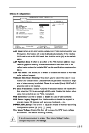
... Enter:Select Sub-Menu F9:Setup Defaults F10:Save & Exit AGP Mode: When an 8X-AGP card is [Disabled]. The default value is installed on K7VM4 motherboard for your PC system, this item will increase the CPU Vcore voltage around +5%. Chipset Configuration: Advanced AMIBIOS SETUP UTILITY - Over Vcore Voltage: Enable this feature...
... Enter:Select Sub-Menu F9:Setup Defaults F10:Save & Exit AGP Mode: When an 8X-AGP card is [Disabled]. The default value is installed on K7VM4 motherboard for your PC system, this item will increase the CPU Vcore voltage around +5%. Chipset Configuration: Advanced AMIBIOS SETUP UTILITY - Over Vcore Voltage: Enable this feature...

User Manual
Page 25
... Port or disable Midi Port. It allows you to enable or disable the onboard LAN feature. If this to monitor the parameters for CPU temperature, Motherboard temperature, CPU fan speed, and critical voltage. OnBoard LAN: This allows you to select Midi IRQ. Configuration options: [Disabled], [330], [300], [290], [292]. OnBoard Game...
... Port or disable Midi Port. It allows you to enable or disable the onboard LAN feature. If this to monitor the parameters for CPU temperature, Motherboard temperature, CPU fan speed, and critical voltage. OnBoard LAN: This allows you to select Midi IRQ. Configuration options: [Disabled], [330], [300], [290], [292]. OnBoard Game...

