User Manual
Page 3
...1 Introduction 4 1.1 Package Contents 4 1.2 Specifications 5 1.3 Motherboard Layout 7 1.4 ASRock I/OTM 8 2 Installation 9 2.1 Screw Holes 9 2.2 Pre-installation Precautions 9 2.3 CPU Installation 10 2.4 Installation of Heatsink and CPU fan 10 2.5 Installation of Memory Modules (DIMM 11 2.6 Expansion Slots 11 2.7 Jumpers..., Boot, and Exit Menus ...... 20 4 Software Support 21 4.1 Installing Operating System 21 4.2 Support CD Information 21 4.2.1 Running Support CD 21 4.2.2 Drivers Menu 21 4.2.3 Utilities Menu 21 4.2.4 ASRock "PC-DIY Live Demo" Program 21 4.2.5 Contact ...
...1 Introduction 4 1.1 Package Contents 4 1.2 Specifications 5 1.3 Motherboard Layout 7 1.4 ASRock I/OTM 8 2 Installation 9 2.1 Screw Holes 9 2.2 Pre-installation Precautions 9 2.3 CPU Installation 10 2.4 Installation of Heatsink and CPU fan 10 2.5 Installation of Memory Modules (DIMM 11 2.6 Expansion Slots 11 2.7 Jumpers..., Boot, and Exit Menus ...... 20 4 Software Support 21 4.1 Installing Operating System 21 4.2 Support CD Information 21 4.2.1 Running Support CD 21 4.2.2 Drivers Menu 21 4.2.3 Utilities Menu 21 4.2.4 ASRock "PC-DIY Live Demo" Program 21 4.2.5 Contact ...
User Manual
Page 4
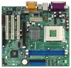
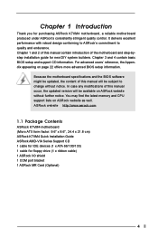
... the latest memory and CPU support lists on page 22 offers more advanced BIOS setup information. ASRock website http://www.asrock.com 1.1 Package Contents ASRock K7VM4 motherboard (Micro ATX form factor: 9.6" x 8.6", 24.4 x 21.8 cm) ASRock K7VM4 Quick Installation Guide ASRock AMD-VIA Series Support CD 1 cable for IDE devices (1 x ATA 66/100/133) 1 cable for purchasing ASRock K7VM4 motherboard, a reliable motherboard produced...
... the latest memory and CPU support lists on page 22 offers more advanced BIOS setup information. ASRock website http://www.asrock.com 1.1 Package Contents ASRock K7VM4 motherboard (Micro ATX form factor: 9.6" x 8.6", 24.4 x 21.8 cm) ASRock K7VM4 Quick Installation Guide ASRock AMD-VIA Series Support CD 1 cable for IDE devices (1 x ATA 66/100/133) 1 cable for purchasing ASRock K7VM4 motherboard, a reliable motherboard produced...

User Manual
Page 5
... up to protect CPU life (ASRock U-COP)(see CAUTION 1) IDE: IDE1: ATA 133 / Ultra DMA Mode 6; IDE2: ATA 133 / Ultra DMA Mode 6; Supports "Plug and Play"; SMBIOS 2.3.1 support; Chassis fan tachometer PCI slots: 3 slots with PCI Specification 2.2 AGP slot: 1 AGP slot, supports 1.5V, 8X/4X AGP card (see CAUTION 3) AMR slot: 1 slot, supports ASRock MR card (optional...
... up to protect CPU life (ASRock U-COP)(see CAUTION 1) IDE: IDE1: ATA 133 / Ultra DMA Mode 6; IDE2: ATA 133 / Ultra DMA Mode 6; Supports "Plug and Play"; SMBIOS 2.3.1 support; Chassis fan tachometer PCI slots: 3 slots with PCI Specification 2.2 AGP slot: 1 AGP slot, supports 1.5V, 8X/4X AGP card (see CAUTION 3) AMR slot: 1 slot, supports ASRock MR card (optional...
User Manual
Page 6
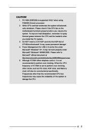
... to perform over clocking, other than the recommended CPU bus frequencies may cause permanent damage! 4. It may not work properly under Microsoft® Windows® XP. Do NOT insert a 3.3V AGP card into the AGP slot of K7VM4 is supported ONLY when using FSB200 (Duron) processor. 2. Please... check if the CPU fan on the motherboard functions properly before you install the PC system. 3. PC1600 (DDR200) is set to...
... to perform over clocking, other than the recommended CPU bus frequencies may cause permanent damage! 4. It may not work properly under Microsoft® Windows® XP. Do NOT insert a 3.3V AGP card into the AGP slot of K7VM4 is supported ONLY when using FSB200 (Duron) processor. 2. Please... check if the CPU fan on the motherboard functions properly before you install the PC system. 3. PC1600 (DDR200) is set to...
User Manual
Page 12
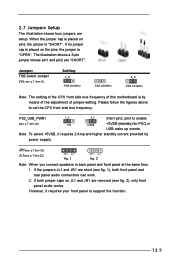
.... 2 Note: When you connect speakers in back panel and front panel at the same time, 1. Note: To select +5VSB, it requires your front panel to support the function. 12 However, it requires 2 Amp and higher standby current provided by means of the adjustment of jumper-setting. When the jumper cap is... is placed on JL1 and JR1 are removed (see p.7 item 11) Setting 1_2 FSB 200MHz FSB 266MHz 2_3 FSB 333MHz Note: The setting of the CPU front side bus frequency of this motherboard is by power supply. JR1(see p.7 item 23) JL1(see p.7 item 29) +5V +5VSB +5VSB (standby) for ...
.... 2 Note: When you connect speakers in back panel and front panel at the same time, 1. Note: To select +5VSB, it requires your front panel to support the function. 12 However, it requires 2 Amp and higher standby current provided by means of the adjustment of jumper-setting. When the jumper cap is... is placed on JL1 and JR1 are removed (see p.7 item 11) Setting 1_2 FSB 200MHz FSB 266MHz 2_3 FSB 333MHz Note: The setting of the CPU front side bus frequency of this motherboard is by power supply. JR1(see p.7 item 23) JL1(see p.7 item 29) +5V +5VSB +5VSB (standby) for ...
User Manual
Page 13
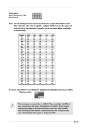
... Please follow the table below to all multiplier-locked or even some unlocked AMD CPU. Please understand that ASRock does not guarantee and support the adjustment of multiplier. Frequencies other than the recommended CPU bus frequencies may not apply to adjust the multiplier of multiplier. FID Jumpers (FID0, FID1, FID2, FID3, FID4) (see p.7 item...
... Please follow the table below to all multiplier-locked or even some unlocked AMD CPU. Please understand that ASRock does not guarantee and support the adjustment of multiplier. Frequencies other than the recommended CPU bus frequencies may not apply to adjust the multiplier of multiplier. FID Jumpers (FID0, FID1, FID2, FID3, FID4) (see p.7 item...

User Manual
Page 16
...p.7 item 14) Chassis fan connector (3-pin CHA_FAN1) (see p.7 item 20) RRXD1 DDTR#1 DDSR#1 CCTS#1 1 RRI#1 RRTS#1 GND TTXD1 DDCD#1 This COM1 header supports a serial port module. 16 O U T- Serial port connector (9-pin COM1) (see p.7 item 13) GND +5VA BACKOUT-R BACKOUT-L 1 A U D - This... connector allows you to attach to the ground pin. CPU fan connector (3-pin CPU_FAN1) (see p.7 item 1) Connect an ATX power supply to the ground pin. O U T- This connector accommodates several system front panel ...
...p.7 item 14) Chassis fan connector (3-pin CHA_FAN1) (see p.7 item 20) RRXD1 DDTR#1 DDSR#1 CCTS#1 1 RRI#1 RRTS#1 GND TTXD1 DDCD#1 This COM1 header supports a serial port module. 16 O U T- Serial port connector (9-pin COM1) (see p.7 item 13) GND +5VA BACKOUT-R BACKOUT-L 1 A U D - This... connector allows you to attach to the ground pin. CPU fan connector (3-pin CPU_FAN1) (see p.7 item 1) Connect an ATX power supply to the ground pin. O U T- This connector accommodates several system front panel ...
User Manual
Page 23
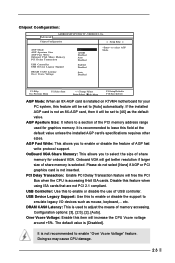
... enable "Over Vcore Voltage" feature. If the installed AGP card is not an 8X-AGP card, then it will free the PCI Bus when the CPU is recommended to leave this feature when using ISA cards that are not PCI 2.1 compliant. AGP Aperture Size: It refers to [4X] as mouse, keyboard... [Auto] automatically. Please do not select [None] if AGP or PCI graphics card is [Disabled]. It is installed on K7VM4 motherboard for your PC system, this to enable or disable the support to select the size of USB controller. OnBoard VGA Share Memory: This allows you to select AGP Mode. F1:Help...
... enable "Over Vcore Voltage" feature. If the installed AGP card is not an 8X-AGP card, then it will free the PCI Bus when the CPU is recommended to leave this feature when using ISA cards that are not PCI 2.1 compliant. AGP Aperture Size: It refers to [4X] as mouse, keyboard... [Auto] automatically. Please do not select [None] if AGP or PCI graphics card is [Disabled]. It is installed on K7VM4 motherboard for your PC system, this to enable or disable the support to select the size of USB controller. OnBoard VGA Share Memory: This allows you to select AGP Mode. F1:Help...


