
User Manual
Page 3
Exit Menu 23 3 Boot Menu 23 5. Security Menu 21 3. Contents 1 Introduction 4 1.1 Package Contents 4 1.2 Specifications 4 1.3 Motherboard Layout 6 1.4 ASRock I/O 7 TM ...2 Installation 8 2.1 Screw Holes 8 2.2 Pre-installation Precautions 8 2.3 CPU Installation 8 2.4 Installation of Heatsink and CPU fan 9 2.5 Installation of... System 18 4.2 Support CD Information 18 4.2.1 Running Support CD 18 4.2.2 Drivers Menu 18 4.2.3 Utilities Menu 18 4.2.4 ASRock "PC-DIY Live Demo" Program 18 4.2.5 Contact Information 18 Appendix 19 1. Advanced Menu 19 2. Power Menu 22 4.
Exit Menu 23 3 Boot Menu 23 5. Security Menu 21 3. Contents 1 Introduction 4 1.1 Package Contents 4 1.2 Specifications 4 1.3 Motherboard Layout 6 1.4 ASRock I/O 7 TM ...2 Installation 8 2.1 Screw Holes 8 2.2 Pre-installation Precautions 8 2.3 CPU Installation 8 2.4 Installation of Heatsink and CPU fan 9 2.5 Installation of... System 18 4.2 Support CD Information 18 4.2.1 Running Support CD 18 4.2.2 Drivers Menu 18 4.2.3 Utilities Menu 18 4.2.4 ASRock "PC-DIY Live Demo" Program 18 4.2.5 Contact Information 18 Appendix 19 1. Advanced Menu 19 2. Power Menu 22 4.

User Manual
Page 4
...advanced users' reference, the Appendix offers more advanced BIOS Setup information. 1.1 Package Contents ASRock K7VT2 motherboard (ATX form factor: 12" x 9.6", 30.5 x 24.4 cm) ASRock K7VT2 Quick Installation Guide ASRock AMD-VIA Series Support CD 1 cable for IDE devices (1 x ATA 66/100/...: ATX form factor (12" x 9.6", 30.5 x 24.4 cm) Supports Socket A (462 pins) for purchasing ASRock K7VT2 motherboard, a reliable motherboard produced under ASRock's consistently stringent quality control. Chassis temperature sensing; Chapter 1 Introduction Thank you for AMD AthlonTM / AthlonTM XP/ DuronTM ...
...advanced users' reference, the Appendix offers more advanced BIOS Setup information. 1.1 Package Contents ASRock K7VT2 motherboard (ATX form factor: 12" x 9.6", 30.5 x 24.4 cm) ASRock K7VT2 Quick Installation Guide ASRock AMD-VIA Series Support CD 1 cable for IDE devices (1 x ATA 66/100/...: ATX form factor (12" x 9.6", 30.5 x 24.4 cm) Supports Socket A (462 pins) for purchasing ASRock K7VT2 motherboard, a reliable motherboard produced under ASRock's consistently stringent quality control. Chassis temperature sensing; Chapter 1 Introduction Thank you for AMD AthlonTM / AthlonTM XP/ DuronTM ...

User Manual
Page 5
...) OS: Microsoft® Windows® 98 SE / ME / 2000 / XP compliant 1. CPU fan tachometer; Supports "Plug and Play"; Although K7VT2 offers stepless control, it is detected, the system will be disabled. Audio Jack: Line Out/ Line In/ Microphone + Game port BIOS: AMI ... if the CPU fan on the chassis will automatically shutdown and the power button on the motherboard functions properly before you resume the system. 2. CPU frequency stepless control (only for two additional USB ports upgrade ASRock I/OTM: PS/2: 1 keyboard port / 1 mouse port; 1 RJ 45 port; 4 ...
...) OS: Microsoft® Windows® 98 SE / ME / 2000 / XP compliant 1. CPU fan tachometer; Supports "Plug and Play"; Although K7VT2 offers stepless control, it is detected, the system will be disabled. Audio Jack: Line Out/ Line In/ Microphone + Game port BIOS: AMI ... if the CPU fan on the chassis will automatically shutdown and the power button on the motherboard functions properly before you resume the system. 2. CPU frequency stepless control (only for two additional USB ports upgrade ASRock I/OTM: PS/2: 1 keyboard port / 1 mouse port; 1 RJ 45 port; 4 ...

User Manual
Page 8
... factor (12" x 9.6", 30.5 x 24.4 cm) motherboard. Chapter 2 Installation K7VT2 is detached from the wall socket before installing or removing the motherboard. Do not over-tighten the screws! Whenever you install or remove any motherboard settings. 1. Unlock the socket by the edges and do ...so may damage the motherboard. 2.2 Pre-installation Precautions ...
... factor (12" x 9.6", 30.5 x 24.4 cm) motherboard. Chapter 2 Installation K7VT2 is detached from the wall socket before installing or removing the motherboard. Do not over-tighten the screws! Whenever you install or remove any motherboard settings. 1. Unlock the socket by the edges and do ...so may damage the motherboard. 2.2 Pre-installation Precautions ...

User Manual
Page 10
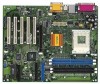
...1. Remove the bracket facing the slot that have the 32-bit PCI interface. Step 4. AMR slot (optional): The AMR slot on K7VT2 motherboard. Step 3. Align the card connector with screws. Step 3. PCI slots: PCI slots are 5 PCI slots, 1 AGP slot and 1 AMR slot (optional...) on K7VT2 motherboard is properly seated. 2.6 Expansion Slots (PCI, AGP, and AMR Slots) There are used to install a graphics card. The ASRock AGP slot has a special locking mechanism which can securely fasten the graphics card inserted. Remove the...
...1. Remove the bracket facing the slot that have the 32-bit PCI interface. Step 4. AMR slot (optional): The AMR slot on K7VT2 motherboard. Step 3. Align the card connector with screws. Step 3. PCI slots: PCI slots are 5 PCI slots, 1 AGP slot and 1 AMR slot (optional...) on K7VT2 motherboard is properly seated. 2.6 Expansion Slots (PCI, AGP, and AMR Slots) There are used to install a graphics card. The ASRock AGP slot has a special locking mechanism which can securely fasten the graphics card inserted. Remove the...

User Manual
Page 12
... IRRX CD-R GND GND CD-L CD1 AUX-R GND GND AUX-L AUX1 Front panel audio connector (9-pin AUDIO1) (see p.6 item 13) USB_PWR P-5 P+5 GND DUMMY ASRock I/OTM already provided 4 default USB ports. L DUMMY A U D - External speaker connector (4-pin SPEAKER 1) (see p.6 item 12) PLED+ PLEDPWRBTN# GND 1... DUMMY RESET# GND HDLEDHDLED+ This connector accommodates several system front panel functions. BLUE Connect to the motherboard BLACK Connect to the IDE devices 80-Pin ATA 100/133 cable Note: To optimize compatibility and performance, please connect your hard ...
... IRRX CD-R GND GND CD-L CD1 AUX-R GND GND AUX-L AUX1 Front panel audio connector (9-pin AUDIO1) (see p.6 item 13) USB_PWR P-5 P+5 GND DUMMY ASRock I/OTM already provided 4 default USB ports. L DUMMY A U D - External speaker connector (4-pin SPEAKER 1) (see p.6 item 12) PLED+ PLEDPWRBTN# GND 1... DUMMY RESET# GND HDLEDHDLED+ This connector accommodates several system front panel functions. BLUE Connect to the motherboard BLACK Connect to the IDE devices 80-Pin ATA 100/133 cable Note: To optimize compatibility and performance, please connect your hard ...

User Manual
Page 14
... you wish to enter the BIOS Setup after POST, restart the system by pressing + + , or by turning the system off and then back on the motherboard stores the BIOS Setup Utility. Chapter 3 BIOS Setup 3.1 BIOS Setup Utility This section explains how to configure your screen. 3.1.1 BIOS Menu Bar The top of...
... you wish to enter the BIOS Setup after POST, restart the system by pressing + + , or by turning the system off and then back on the motherboard stores the BIOS Setup Utility. Chapter 3 BIOS Setup 3.1 BIOS Setup Utility This section explains how to configure your screen. 3.1.1 BIOS Menu Bar The top of...

User Manual
Page 18
...necessary drivers to your OS documentation for more about ASRock, welcome to ASRock's website: http://www.asrock.com; Chapter 4 Software Support 4.1 Install Operating System This motherboard supports various Windows operating systems (98SE / ME / 2000 / XP). Because motherboard settings and hardware options vary, use the setup ... Microsoft Media Player to play the file. 4.2.5 Contact Information If you need to contact ASRock or want to know more information. 4.2 Support CD Information The Support CD that came with the motherboard contains necessary drivers and useful utilities that the...
...necessary drivers to your OS documentation for more about ASRock, welcome to ASRock's website: http://www.asrock.com; Chapter 4 Software Support 4.1 Install Operating System This motherboard supports various Windows operating systems (98SE / ME / 2000 / XP). Because motherboard settings and hardware options vary, use the setup ... Microsoft Media Player to play the file. 4.2.5 Contact Information If you need to contact ASRock or want to know more information. 4.2 Support CD Information The Support CD that came with the motherboard contains necessary drivers and useful utilities that the...

User Manual
Page 19
... you the following BIOS setup menus: "Advanced," "Security," "Power," "Boot," and "Exit." 1. Chipset Configuration: AGP Mode: This motherboard supports the AGP 4X interface that transfers video data at the default value unless your AGP card requires other value as operating frequency: [200MHz...thoroughly knows the feature. Appendix: Advanced BIOS Setup This section will free the PCI Bus when the CPU is selected, the motherboard detects the memory module(s) inserted and automatically assigns appropriate frequency. Advanced BIOS Setup Menu Spread Spectrum: This field should always be...
... you the following BIOS setup menus: "Advanced," "Security," "Power," "Boot," and "Exit." 1. Chipset Configuration: AGP Mode: This motherboard supports the AGP 4X interface that transfers video data at the default value unless your AGP card requires other value as operating frequency: [200MHz...thoroughly knows the feature. Appendix: Advanced BIOS Setup This section will free the PCI Bus when the CPU is selected, the motherboard detects the memory module(s) inserted and automatically assigns appropriate frequency. Advanced BIOS Setup Menu Spread Spectrum: This field should always be...

User Manual
Page 21
... check the status of the User Password. [Clear]: No password has been set. [Set]: User password has been set [Auto] or [Disabled] for CPU temperature, Motherboard temperature, CPU fan speed, and critical voltage. 2.
... check the status of the User Password. [Clear]: No password has been set. [Set]: User password has been set [Auto] or [Disabled] for CPU temperature, Motherboard temperature, CPU fan speed, and critical voltage. 2.

