
User Manual
Page 3
... Contents 5 1.2 Specifications 6 1.3 Supported PCI Express VGA Card List for SATA / SATAII HDDs and eSATAII Devices 31 2.13 Using SATA / SATAII HDDs With RAID Functions 32 2.14 Using SATA / SATAII HDDs Without RAID Functions 33 2.15 Untied Overclocking Technology 33 3 . BIOS SETUP UTILITY 34 3.1 Introduction 34 3.1.1 BIOS Menu Bar 34 3.1.2 Navigation Keys 35 3.2 Main Screen 35 3.3 Advanced Screen 36 3.3.1 CPU Configuration 37 3.3.2 Chipset Configuration 39 3.3.3 ACPI Configuration 41 3.3.4 IDE Configuration 42 3.3.5 PCIPnP Configuration 44 3.3.6 Floppy Configuration 45...
... Contents 5 1.2 Specifications 6 1.3 Supported PCI Express VGA Card List for SATA / SATAII HDDs and eSATAII Devices 31 2.13 Using SATA / SATAII HDDs With RAID Functions 32 2.14 Using SATA / SATAII HDDs Without RAID Functions 33 2.15 Untied Overclocking Technology 33 3 . BIOS SETUP UTILITY 34 3.1 Introduction 34 3.1.1 BIOS Menu Bar 34 3.1.2 Navigation Keys 35 3.2 Main Screen 35 3.3 Advanced Screen 36 3.3.1 CPU Configuration 37 3.3.2 Chipset Configuration 39 3.3.3 ACPI Configuration 41 3.3.4 IDE Configuration 42 3.3.5 PCIPnP Configuration 44 3.3.6 Floppy Configuration 45...

User Manual
Page 7
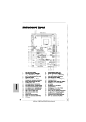
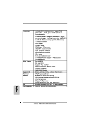
Front panel audio connector - 2 x USB 2.0 headers (support 4 USB 2.0 ports) (see CAUTION 7) - 2 x ATA133 IDE connectors (support 4 x IDE devices) - 1 x Floppy connector - 1 x IR header - 1 x Game header - ACPI 1.1 Compliance Wake Up Events - SMBIOS 2.3.1 Support - Voltage Monitoring: +12V, +5V, +3.3V, Vcore - CD in header - SLI/XFIRE power connector - Motherboard Temperature Sensing - Chassis Fan Tachometer - CPU/Chassis FAN connector - 20 pin ATX power connector - 4 pin 12V power connector - Drivers, Utilities, AntiVirus Software (Trial Version) - Microsoft® Windows...
Front panel audio connector - 2 x USB 2.0 headers (support 4 USB 2.0 ports) (see CAUTION 7) - 2 x ATA133 IDE connectors (support 4 x IDE devices) - 1 x Floppy connector - 1 x IR header - 1 x Game header - ACPI 1.1 Compliance Wake Up Events - SMBIOS 2.3.1 Support - Voltage Monitoring: +12V, +5V, +3.3V, Vcore - CD in header - SLI/XFIRE power connector - Motherboard Temperature Sensing - Chassis Fan Tachometer - CPU/Chassis FAN connector - 20 pin ATX power connector - 4 pin 12V power connector - Drivers, Utilities, AntiVirus Software (Trial Version) - Microsoft® Windows...
User Manual
Page 8
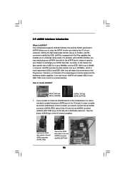
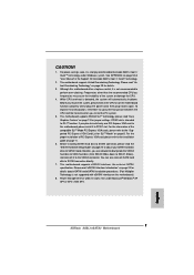
... "Supported PCI Express VGA Card List for jumper settings. You can also connect SATA hard disk to enable AMD's Cool 'n' QuietTM technology. 2. This motherboard supports eSATAII interface, the external SATAII specification. See APPENDIX on page 9. Please read "Dual Graphics Feature" on page 17 for SLITM Mode" on page 52 to SATAII connector directly. 7. To improve heat dissipation, remember to spray thermal grease between the CPU and the heatsink when you plan to install only one PCI Express VGA card...
... "Supported PCI Express VGA Card List for jumper settings. You can also connect SATA hard disk to enable AMD's Cool 'n' QuietTM technology. 2. This motherboard supports eSATAII interface, the external SATAII specification. See APPENDIX on page 9. Please read "Dual Graphics Feature" on page 17 for SLITM Mode" on page 52 to SATAII connector directly. 7. To improve heat dissipation, remember to spray thermal grease between the CPU and the heatsink when you plan to install only one PCI Express VGA card...
User Manual
Page 23
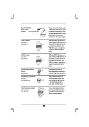
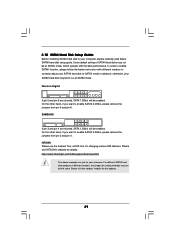
... the power connector on the I /O panel are not sufficient, this USB 2.0 header is an interface for front panel audio cable that allows convenient connection and control of audio devices. 23 Front Panel Audio Header (9-pin HD_AUDIO1) (see p.10 No. 26) IRTX +5VSB DUMMY 1 GND IRRX CD1 CD-R GND GND CD-L ASRock eSATAII I /O accommodates 4 default USB 2.0 ports. Serial ATA (SATA) Power Cable (Optional) connect to the SATA HDD power connector connect to the power supply Please connect the black end of SATA power cable to support 2 additional USB 2.0 ports. USB 2.0 Header (9-pin...
... the power connector on the I /O panel are not sufficient, this USB 2.0 header is an interface for front panel audio cable that allows convenient connection and control of audio devices. 23 Front Panel Audio Header (9-pin HD_AUDIO1) (see p.10 No. 26) IRTX +5VSB DUMMY 1 GND IRRX CD1 CD-R GND GND CD-L ASRock eSATAII I /O accommodates 4 default USB 2.0 ports. Serial ATA (SATA) Power Cable (Optional) connect to the SATA HDD power connector connect to the power supply Please connect the black end of SATA power cable to support 2 additional USB 2.0 ports. USB 2.0 Header (9-pin...

User Manual
Page 24
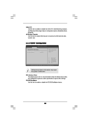
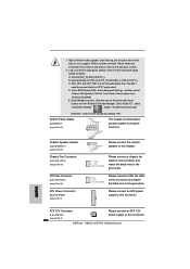
Enter BIOS Setup Utility. System Panel Header (9-pin PANEL1) (see p.10 No. 22) Chassis Speaker Header (4-pin SPEAKER 1) (see p.10 No. 39) Please connect a CPU fan cable to this connector and match the black wire to MIC2_L. Please connect the chassis speaker to this connector and match the black wire to the ground pin. If you use AC'97 audio panel, please install it to [Enabled]. Click "Audio I/O", select "Connector Settings" , choose "Disable front panel jack detection", and save the change by clicking "OK". Chassis Fan Connector (3-pin CHA_FAN1) (see...
Enter BIOS Setup Utility. System Panel Header (9-pin PANEL1) (see p.10 No. 22) Chassis Speaker Header (4-pin SPEAKER 1) (see p.10 No. 39) Please connect a CPU fan cable to this connector and match the black wire to MIC2_L. Please connect the chassis speaker to this connector and match the black wire to the ground pin. If you use AC'97 audio panel, please install it to [Enabled]. Click "Audio I/O", select "Connector Settings" , choose "Disable front panel jack detection", and save the change by clicking "OK". Chassis Fan Connector (3-pin CHA_FAN1) (see...
User Manual
Page 26
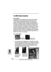
... will replace USB 2.0 and IEEE 1394 to 400Mb/ s. Connect the SATA data cable to the red SATAII connector (SATAII_RED) Connect the SATA data cable to install eSATAII? Currently, on the basis of your chassis to connect the red SATAII connector (SATAII_RED; Then the bottom eSATAII port of opening your computer, offering the high speed data transfer rate up to be a trend for IEEE 1394 is enabled. SATAII_RED...
... will replace USB 2.0 and IEEE 1394 to 400Mb/ s. Connect the SATA data cable to the red SATAII connector (SATAII_RED) Connect the SATA data cable to install eSATAII? Currently, on the basis of your chassis to connect the red SATAII connector (SATAII_RED; Then the bottom eSATAII port of opening your computer, offering the high speed data transfer rate up to be a trend for IEEE 1394 is enabled. SATAII_RED...
User Manual
Page 29
... for details: http://www.hitachigst.com/hdd/support/download.htm The above examples are shorted, SATA 1.5Gb/s will be enabled. Some default setting of different vendors, the jumper pin setting methods may fail to run at SATAII mode, which operate with different vendors to correctly adjust your SATAII hard disk to SATAII mode in advance; 2.10 SATAII Hard Disk Setup Guide Before installing SATAII hard disk to your computer, please carefully read...
... for details: http://www.hitachigst.com/hdd/support/download.htm The above examples are shorted, SATA 1.5Gb/s will be enabled. Some default setting of different vendors, the jumper pin setting methods may fail to run at SATAII mode, which operate with different vendors to correctly adjust your SATAII hard disk to SATAII mode in advance; 2.10 SATAII Hard Disk Setup Guide Before installing SATAII hard disk to your computer, please carefully read...
User Manual
Page 44
... cards' specifications require other settings. Use this item to malfunction. Configuration options: [Disabled], [Auto], [Enabled]. 32-Bit Data Transfer Use this section may cause the system to enable or disable the S.M.A.R.T. (Self-Monitoring, Analysis, and Reporting Technology) feature. PCI IDE BusMaster Use this item to maximize the IDE hard disk data transfer rate. 3.3.5 PCIPnP Configuration BIOS SETUP UTILITY Advanced Advanced PCI / PnP Settings PCI Latency Timer PCI IDE BusMaster [32] [Enabled] Value in this item to enable 32-bit access to enable or disable the PCI IDE...
... cards' specifications require other settings. Use this item to malfunction. Configuration options: [Disabled], [Auto], [Enabled]. 32-Bit Data Transfer Use this section may cause the system to enable or disable the S.M.A.R.T. (Self-Monitoring, Analysis, and Reporting Technology) feature. PCI IDE BusMaster Use this item to maximize the IDE hard disk data transfer rate. 3.3.5 PCIPnP Configuration BIOS SETUP UTILITY Advanced Advanced PCI / PnP Settings PCI Latency Timer PCI IDE BusMaster [32] [Enabled] Value in this item to enable 32-bit access to enable or disable the PCI IDE...
User Manual
Page 47
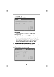
... connected, "Auto" option will start to enable or disable the use of the CPU temperature, motherboard temperature, CPU fan speed, chassis fan speed, and the critical voltage. 3.3.8 USB Configuration BIOS SETUP UTILITY Advanced USB Configuration USB Controller USB 2.0 Support Legacy USB Support [Enabled] [Enabled] [Disabled] To enable or disable the onboard USB controllers. +F1 F9 F10 ESC Select Screen Select Item Change Option General Help Load Defaults Save and Exit Exit v02.54 (C) Copyright 1985-2003, American Megatrends, Inc. BIOS SETUP UTILITY Main Advanced H/W Monitor Boot...
... connected, "Auto" option will start to enable or disable the use of the CPU temperature, motherboard temperature, CPU fan speed, chassis fan speed, and the critical voltage. 3.3.8 USB Configuration BIOS SETUP UTILITY Advanced USB Configuration USB Controller USB 2.0 Support Legacy USB Support [Enabled] [Enabled] [Disabled] To enable or disable the onboard USB controllers. +F1 F9 F10 ESC Select Screen Select Item Change Option General Help Load Defaults Save and Exit Exit v02.54 (C) Copyright 1985-2003, American Megatrends, Inc. BIOS SETUP UTILITY Main Advanced H/W Monitor Boot...

User Manual
Page 51
...-bit. The CD automatically displays the Main Menu if "AUTORUN" is enabled in this chapter for more about ASRock, welcome to display the menus. 4.2.2 Drivers Menu The Drivers Menu shows the available devices drivers including ASRock Express GbL PCI Express LAN card driver if the system detects the installed devices. Click on the file "ASSETUP.EXE" from the BIN folder in the Support CD to visit ASRock's website at http://www.asrock.com; 4. Because motherboard settings and hardware options...
...-bit. The CD automatically displays the Main Menu if "AUTORUN" is enabled in this chapter for more about ASRock, welcome to display the menus. 4.2.2 Drivers Menu The Drivers Menu shows the available devices drivers including ASRock Express GbL PCI Express LAN card driver if the system detects the installed devices. Click on the file "ASSETUP.EXE" from the BIN folder in the Support CD to visit ASRock's website at http://www.asrock.com; 4. Because motherboard settings and hardware options...
User Manual
Page 52
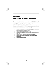
... to install "AMD Processor Driver" from the "Support CD" first. button. Click OK to enable AMD's Cool 'n' QuietTM technology: 1. Select Settings, then Control Panel. 2. From the Windows 2000 / XP/ XP 64-bit operating system, click the Start button. Double-click the Display icon in the Control Panel then select the Screen Saver tab. 4. The following dialog box appears. 5. From the Power schemes combo list box, select Minimal Power Management. 6. APPENDIX: AMD's Cool 'n' QuietTM Technology For power...
... to install "AMD Processor Driver" from the "Support CD" first. button. Click OK to enable AMD's Cool 'n' QuietTM technology: 1. Select Settings, then Control Panel. 2. From the Windows 2000 / XP/ XP 64-bit operating system, click the Start button. Double-click the Display icon in the Control Panel then select the Screen Saver tab. 4. The following dialog box appears. 5. From the Power schemes combo list box, select Minimal Power Management. 6. APPENDIX: AMD's Cool 'n' QuietTM Technology For power...
Quick Installation Guide
Page 2
...PANEL1) 23 Chassis Speaker Header (SPEAKER 1) 24 Clear CMOS Jumper (CLRCMOS1) 25 Game Port Header (GAME1) 26 Internal Audio Connector: CD1 (Black) 27 PCI Slots (PCI1- 3) 28 Front Panel Audio Header (HD_AUDIO1) 29 PCI Express x 1 / x 8 Slot (PCIE3) 30 J21 Jumper 31 PCI Express x 1 Slot (PCIE2) 32 J11 / J12 Jumpers 33 PCI Express x 16 / x 8 Slot (PCIE1) 34 SLI / XFIRE Power Connector 35 Future CPU Port (FUTURE_CPU_PORT1) 36 J1 / J2 / J3 / J4 / J7 / J8 / J9 / J10 Jumpers 37 eSATAII Connector (eSATAII_TOP) 38 eSATAII Connector (eSATAII_BOTTOM) 39 CPU Fan Connector (CPU_FAN1) 2 ASRock K8SLI-eSATA2...
...PANEL1) 23 Chassis Speaker Header (SPEAKER 1) 24 Clear CMOS Jumper (CLRCMOS1) 25 Game Port Header (GAME1) 26 Internal Audio Connector: CD1 (Black) 27 PCI Slots (PCI1- 3) 28 Front Panel Audio Header (HD_AUDIO1) 29 PCI Express x 1 / x 8 Slot (PCIE3) 30 J21 Jumper 31 PCI Express x 1 Slot (PCIE2) 32 J11 / J12 Jumpers 33 PCI Express x 16 / x 8 Slot (PCIE1) 34 SLI / XFIRE Power Connector 35 Future CPU Port (FUTURE_CPU_PORT1) 36 J1 / J2 / J3 / J4 / J7 / J8 / J9 / J10 Jumpers 37 eSATAII Connector (eSATAII_TOP) 38 eSATAII Connector (eSATAII_BOTTOM) 39 CPU Fan Connector (CPU_FAN1) 2 ASRock K8SLI-eSATA2...
Quick Installation Guide
Page 6
... 4 USB 2.0 ports) (see CAUTION 7) - 2 x ATA133 IDE connectors (support 4 x IDE devices) - 1 x Floppy connector - 1 x IR header - 1 x Game header - CD in header - AMI Legal BIOS - ACPI 1.1 Compliance Wake Up Events - CPU Temperature Sensing - CPU Fan Tachometer - SLI/XFIRE power connector - Chassis Fan Tachometer - Microsoft® Windows® 2000 / XP / XP 64-bit compliant - Supports jumperfree - Drivers, Utilities, AntiVirus Software (Trial Version) - CPU Overheat Shutdown to Protect CPU Life - FCC, CE, Microsoft® WHQL Certificated English 6 ASRock K8SLI-eSATA2...
... 4 USB 2.0 ports) (see CAUTION 7) - 2 x ATA133 IDE connectors (support 4 x IDE devices) - 1 x Floppy connector - 1 x IR header - 1 x Game header - CD in header - AMI Legal BIOS - ACPI 1.1 Compliance Wake Up Events - CPU Temperature Sensing - CPU Fan Tachometer - SLI/XFIRE power connector - Chassis Fan Tachometer - Microsoft® Windows® 2000 / XP / XP 64-bit compliant - Supports jumperfree - Drivers, Utilities, AntiVirus Software (Trial Version) - CPU Overheat Shutdown to Protect CPU Life - FCC, CE, Microsoft® WHQL Certificated English 6 ASRock K8SLI-eSATA2...
Quick Installation Guide
Page 7
... information of PCI Express VGA card, please refer to SATAII connector directly. 7. You can also connect SATA hard disk to the installation guide on page 29 for jumper settings. Please read the "SATAII Hard Disk Setup Guide" on the motherboard functions properly and unplug the power cord, then plug it to enable AMD's Cool 'n' QuietTM technology under Microsoft® Windows® XP SP1 or SP2 / 2000 SP4. 7 ASRock K8SLI-eSATA2 Motherboard English Frequencies other than the recommended CPU bus frequencies may cause...
... information of PCI Express VGA card, please refer to SATAII connector directly. 7. You can also connect SATA hard disk to the installation guide on page 29 for jumper settings. Please read the "SATAII Hard Disk Setup Guide" on the motherboard functions properly and unplug the power cord, then plug it to enable AMD's Cool 'n' QuietTM technology under Microsoft® Windows® XP SP1 or SP2 / 2000 SP4. 7 ASRock K8SLI-eSATA2 Motherboard English Frequencies other than the recommended CPU bus frequencies may cause...
Quick Installation Guide
Page 11
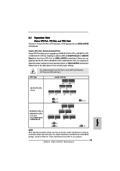
... CPU Port, 3 PCI slots and 3 PCI Express slots on K8SLI-eSATA2 motherboard. This yellow-colored Future CPU Port is bundled in your motherboard package, and please follow the "Jumper Cap Remover Instruction" to use the tool, Jumper Cap Remover, to help you to upgrade your AMD K8 754-Pin CPU to the table below for those required jumpers on ASRock 939CPU Board or AM2CPU Board) J1 J2 J3 J4 J11 J12 J13 NOTE When adjusting the jumper settings, you...
... CPU Port, 3 PCI slots and 3 PCI Express slots on K8SLI-eSATA2 motherboard. This yellow-colored Future CPU Port is bundled in your motherboard package, and please follow the "Jumper Cap Remover Instruction" to use the tool, Jumper Cap Remover, to help you to upgrade your AMD K8 754-Pin CPU to the table below for those required jumpers on ASRock 939CPU Board or AM2CPU Board) J1 J2 J3 J4 J11 J12 J13 NOTE When adjusting the jumper settings, you...
Quick Installation Guide
Page 18
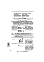
... (SATAII) connectors support SATAII_ORANGE SATA data cables for external SATAII function. ASRock K8SLI-eSATA2 Motherboard English Primary IDE Connector (Blue) Secondary IDE Connector (Black) (39-pin IDE1, see p.2 No. 8) (39-pin IDE2, see p.2 No. 7) connect the blue end to the motherboard connect the black end to the secondary IDE connector (IDE2, black). Besides, to optimize compatibility and performance, please connect your IDE device vendor for the details. SATAII_RED and SATAII_ORANGE connectors can be used for...
... (SATAII) connectors support SATAII_ORANGE SATA data cables for external SATAII function. ASRock K8SLI-eSATA2 Motherboard English Primary IDE Connector (Blue) Secondary IDE Connector (Black) (39-pin IDE1, see p.2 No. 8) (39-pin IDE2, see p.2 No. 7) connect the blue end to the motherboard connect the black end to the secondary IDE connector (IDE2, black). Besides, to optimize compatibility and performance, please connect your IDE device vendor for the details. SATAII_RED and SATAII_ORANGE connectors can be used for...
Quick Installation Guide
Page 19
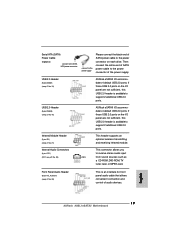
... default USB 2.0 ports. English 19 ASRock K8SLI-eSATA2 Motherboard Infrared Module Header (5-pin IR1) (see p.2 No. 28) This is available to support 2 additional USB 2.0 ports. Internal Audio Connectors (4-pin CD1) (CD1: see p.2 No. 26) This connector allows you to the power connector of the power supply. Front Panel Audio Header (9-pin HD_AUDIO1) (see p.2 No. 21) This header supports an optional wireless transmitting and receiving infrared module. Serial ATA (SATA) Power Cable (Optional) connect to the SATA HDD power connector connect to the power supply Please connect...
... default USB 2.0 ports. English 19 ASRock K8SLI-eSATA2 Motherboard Infrared Module Header (5-pin IR1) (see p.2 No. 28) This is available to support 2 additional USB 2.0 ports. Internal Audio Connectors (4-pin CD1) (CD1: see p.2 No. 26) This connector allows you to the power connector of the power supply. Front Panel Audio Header (9-pin HD_AUDIO1) (see p.2 No. 21) This header supports an optional wireless transmitting and receiving infrared module. Serial ATA (SATA) Power Cable (Optional) connect to the SATA HDD power connector connect to the power supply Please connect...
Quick Installation Guide
Page 20
... [Enabled]. Enter Windows system. High Definition Audio supports Jack Sensing, but the panel wire on the lower right hand taskbar to enter Realtek HD Audio Manager. D. E. Click the icon on the chassis must support HDA to this connector. (see p.2 No. 2) 20 ASRock K8SLI-eSATA2 Motherboard English System Panel Header (9-pin PANEL1) (see p.2 No. 4) Please connect the chassis speaker to this connector and match the black wire to this connector. Set the Front Panel Control option from [Auto] to OUT2_L. Please connect an ATX power supply...
... [Enabled]. Enter Windows system. High Definition Audio supports Jack Sensing, but the panel wire on the lower right hand taskbar to enter Realtek HD Audio Manager. D. E. Click the icon on the chassis must support HDA to this connector. (see p.2 No. 2) 20 ASRock K8SLI-eSATA2 Motherboard English System Panel Header (9-pin PANEL1) (see p.2 No. 4) Please connect the chassis speaker to this connector and match the black wire to this connector. Set the Front Panel Control option from [Auto] to OUT2_L. Please connect an ATX power supply...
Quick Installation Guide
Page 22
... the high speed data transfer rate up to connect the red SATAII connector (SATAII_RED; SATAII_RED and SATAII_ORANGE eSATAII_TOP and eSATAII_BOTTOM 1. For example, with eSATAII interface, you to 3.0Gb/s, and the convenient mobility like USB. How to the red eSATAII connector (eSATAII_BOTTOM) 22 ASRock K8SLI-eSATA2 Motherboard eSATAII is equipped with a SATA data cable first. In order to enable the bottom eSATAII port of the...
... the high speed data transfer rate up to connect the red SATAII connector (SATAII_RED; SATAII_RED and SATAII_ORANGE eSATAII_TOP and eSATAII_BOTTOM 1. For example, with eSATAII interface, you to 3.0Gb/s, and the convenient mobility like USB. How to the red eSATAII connector (eSATAII_BOTTOM) 22 ASRock K8SLI-eSATA2 Motherboard eSATAII is equipped with a SATA data cable first. In order to enable the bottom eSATAII port of the...
Quick Installation Guide
Page 30
... CD-ROM drive. If you to scroll through its test routines. The Support CD that came with its various sub-menus and to enter BIOS Setup after POST, please restart the system by pressing + + , or pressing the reset button on the motherboard stores BIOS Setup Utility. 3. The BIOS Setup program is designed to display the menus. 30 ASRock K8SLI-eSATA2 Motherboard English BIOS Information The Flash Memory on the system chassis. If the Main Menu does...
... CD-ROM drive. If you to scroll through its test routines. The Support CD that came with its various sub-menus and to enter BIOS Setup after POST, please restart the system by pressing + + , or pressing the reset button on the motherboard stores BIOS Setup Utility. 3. The BIOS Setup program is designed to display the menus. 30 ASRock K8SLI-eSATA2 Motherboard English BIOS Information The Flash Memory on the system chassis. If the Main Menu does...


