RAID Installation Guide
Page 2
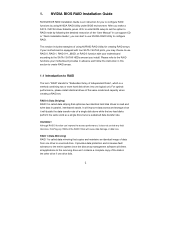
...when creating a RAID set the option to a second drive. Hot-Plug any fault tolerance. 1. Please refer to the RAID functions your motherboard according to set . It will improve data access and storage since the disk array management software will direct all applications to configure RAID.... HDDs amount you install. Although RAID 0 function can start to use RAID 0, RAID 1, RAID 0+1, JBOD, or RAID 5 function with your motherboard provides in advance and follow the instruction in this section to create RAID arrays. 1.1 Introduction to RAID The term "RAID" stands for you to...
...when creating a RAID set the option to a second drive. Hot-Plug any fault tolerance. 1. Please refer to the RAID functions your motherboard according to set . It will improve data access and storage since the disk array management software will direct all applications to configure RAID.... HDDs amount you install. Although RAID 0 function can start to use RAID 0, RAID 1, RAID 0+1, JBOD, or RAID 5 function with your motherboard provides in advance and follow the instruction in this section to create RAID arrays. 1.1 Introduction to RAID The term "RAID" stands for you to...
RAID Installation Guide
Page 12
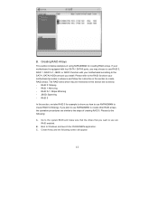
RAID 0: Striping - Please do the following screen will appear. 12 B. C. B. If your motherboard is equipped with four SATA / SATAII ports, you install. RAID 1: Mirroring - RAID 0+1: Stripe Mirroring - The RAID items which may choose to use are...RAID arrays. Create Array and the following : A. JBOD: Spanning - Please refer to the RAID functions your motherboard according to use RAID 0, RAID 1, RAID 0+1, JBOD, or RAID 5 function with your motherboard provides in advance and follow the instruction in this section are RAID enabled. Boot to create RAID arrays. ...
RAID 0: Striping - Please do the following screen will appear. 12 B. C. B. If your motherboard is equipped with four SATA / SATAII ports, you install. RAID 1: Mirroring - RAID 0+1: Stripe Mirroring - The RAID items which may choose to use are...RAID arrays. Create Array and the following : A. JBOD: Spanning - Please refer to the RAID functions your motherboard according to use RAID 0, RAID 1, RAID 0+1, JBOD, or RAID 5 function with your motherboard provides in advance and follow the instruction in this section are RAID enabled. Boot to create RAID arrays. ...
User Manual
Page 2
...without written consent of ASRock Inc. CALIFORNIA, ...regulations passed by the California Legislature. ASRock assumes no event shall ASRock, its directors, officers, employees, ... defect or error in this manual, ASRock does not provide warranty of any kind...interruption of business and the like), even if ASRock has been advised of the possibility of such damages...and should not be constructed as a commitment by ASRock. Operation is subject to the contents of the ...www.dtsc.ca.gov/hazardouswaste/perchlorate" ASRock Website: http://www.asrock.com 2 This device complies with Part 15...
...without written consent of ASRock Inc. CALIFORNIA, ...regulations passed by the California Legislature. ASRock assumes no event shall ASRock, its directors, officers, employees, ... defect or error in this manual, ASRock does not provide warranty of any kind...interruption of business and the like), even if ASRock has been advised of the possibility of such damages...and should not be constructed as a commitment by ASRock. Operation is subject to the contents of the ...www.dtsc.ca.gov/hazardouswaste/perchlorate" ASRock Website: http://www.asrock.com 2 This device complies with Part 15...

User Manual
Page 3
... 3.1.2 Navigation Keys 30 3.2 Main Screen 30 3.3 Smart Screen 32 3.4 Advanced Screen 33 3.4.1 CPU Configuration 33 3.4.2 Chipset Configuration 37 3.4.3 ACPI Configuration 39 3 Introduction 5 1.1 Package Contents 5 1.2 Specifications 6 1.3 Motherboard Layout 10 1.4 I/O Panel 11 2 .
... 3.1.2 Navigation Keys 30 3.2 Main Screen 30 3.3 Smart Screen 32 3.4 Advanced Screen 33 3.4.1 CPU Configuration 33 3.4.2 Chipset Configuration 37 3.4.3 ACPI Configuration 39 3 Introduction 5 1.1 Package Contents 5 1.2 Specifications 6 1.3 Motherboard Layout 10 1.4 I/O Panel 11 2 .

User Manual
Page 5
... the model you for purchasing ASRock N68-GS / N68-S motherboard, a reliable motherboard produced under ASRock's consistently stringent quality control. Because the motherboard specifications and the BIOS software might be updated, the content of the motherboard and step-by-step guide to quality and endurance. www.asrock.com/support/index.asp 1.1 Package Contents One ASRock N68-GS / N68-S Motherboard (Micro ATX Form Factor: 9.6-in...
... the model you for purchasing ASRock N68-GS / N68-S motherboard, a reliable motherboard produced under ASRock's consistently stringent quality control. Because the motherboard specifications and the BIOS software might be updated, the content of the motherboard and step-by-step guide to quality and endurance. www.asrock.com/support/index.asp 1.1 Package Contents One ASRock N68-GS / N68-S Motherboard (Micro ATX Form Factor: 9.6-in...
User Manual
Page 8
...maximum shared memory size is defined by the chipset vendor and is a user-friendly ASRock overclocking tool which allows you to read the installation guide of your own risk and expense. This motherboard supports Dual Channel Memory Technology. It should be less than 4GB for the reservation ...for CPU support list. ASRock website http://www.asrock.com 5. Overclocking may be done at your system. WARNING Please realize ...
...maximum shared memory size is defined by the chipset vendor and is a user-friendly ASRock overclocking tool which allows you to read the installation guide of your own risk and expense. This motherboard supports Dual Channel Memory Technology. It should be less than 4GB for the reservation ...for CPU support list. ASRock website http://www.asrock.com 5. Overclocking may be done at your system. WARNING Please realize ...

User Manual
Page 9
..., it is detected, the system will overclock the chipset/CPU reference clock. ASRock website: http://www.asrock.com 11. To improve heat dissipation, remember to perform over-clocking. Enabling this motherboard offers stepless control, it is enabled, it back again. To use FAT32/...CPU bus frequencies may not be noted that delivers unparalleled power savings. However, we can update your system. 9 This motherboard supports ASRock AM2 Boost overclocking technology. Please visit our website for all CPU/DRAM configurations. 10. Featuring an advanced proprietary hardware and ...
..., it is detected, the system will overclock the chipset/CPU reference clock. ASRock website: http://www.asrock.com 11. To improve heat dissipation, remember to perform over-clocking. Enabling this motherboard offers stepless control, it is enabled, it back again. To use FAT32/...CPU bus frequencies may not be noted that delivers unparalleled power savings. However, we can update your system. 9 This motherboard supports ASRock AM2 Boost overclocking technology. Please visit our website for all CPU/DRAM configurations. 10. Featuring an advanced proprietary hardware and ...
User Manual
Page 10
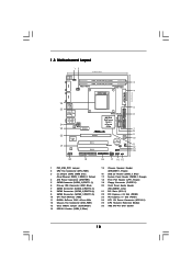
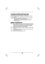
... (PCIE2) 23 PCI Express x1 Slot (PCIE1) 24 ATX 12V Power Connector (ATX12V1) 25 CPU Heatsink Retention Module 26 AM2 940-Pin CPU Socket 10 1.3 Motherboard Layout 12 17.8cm (7.0-in) PS2 Mouse PS2 Keyboard COM1 1 PS2_USB_PW1 DDRII_2 (64 bit, 240-pFinSmBod8u0le0) 3 DDRII_1 (64 bit, 240-pin module) AM2+/AM3 Dual...
... (PCIE2) 23 PCI Express x1 Slot (PCIE1) 24 ATX 12V Power Connector (ATX12V1) 25 CPU Heatsink Retention Module 26 AM2 940-Pin CPU Socket 10 1.3 Motherboard Layout 12 17.8cm (7.0-in) PS2 Mouse PS2 Keyboard COM1 1 PS2_USB_PW1 DDRII_2 (64 bit, 240-pFinSmBod8u0le0) 3 DDRII_1 (64 bit, 240-pin module) AM2+/AM3 Dual...

User Manual
Page 11
... In (Light Blue) 4 Front Speaker (Lime) * 5 Microphone (Pink) 7 6 6 USB 2.0 Ports (USB01) 7 USB 2.0 Ports (USB23) 8 VGA Port 9 COM Port 10 PS/2 Keyboard Port (Purple) * For N68-GS motherboard, please refer to the table below instructions according to the OS you are allowed to select "2 Channel" or "4 Channel". Click "Power" to save your change...
... In (Light Blue) 4 Front Speaker (Lime) * 5 Microphone (Pink) 7 6 6 USB 2.0 Ports (USB01) 7 USB 2.0 Ports (USB23) 8 VGA Port 9 COM Port 10 PS/2 Keyboard Port (Purple) * For N68-GS motherboard, please refer to the table below instructions according to the OS you are allowed to select "2 Channel" or "4 Channel". Click "Power" to save your change...
User Manual
Page 12
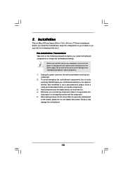
...ensure that the power is switched off or the power cord is a Micro ATX form factor (9.6-in x 7.0-in the bag that the motherboard fits into it on the carpet or the like. Before you install or remove any component. 2. Hold components by the edges and do...do not over-tighten the screws! To avoid damaging the motherboard components due to the motherboard, peripherals, and/or components. 1. 2. Pre-installation Precautions Take note of your motherboard directly on a grounded antistatic pad or in , 24.4 cm x 17.8 cm) motherboard. Failure to do not touch the ICs. 4. Unplug the...
...ensure that the power is switched off or the power cord is a Micro ATX form factor (9.6-in x 7.0-in the bag that the motherboard fits into it on the carpet or the like. Before you install or remove any component. 2. Hold components by the edges and do...do not over-tighten the screws! To avoid damaging the motherboard components due to the motherboard, peripherals, and/or components. 1. 2. Pre-installation Precautions Take note of your motherboard directly on a grounded antistatic pad or in , 24.4 cm x 17.8 cm) motherboard. Failure to do not touch the ICs. 4. Unplug the...
User Manual
Page 13
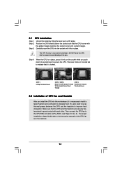
... is necessary to install a larger heatsink and cooling fan to the CPU FAN connector (CPU_FAN1, see Page 10, No. 2). Carefully insert the CPU into this motherboard, it is in place, press it fits in one correct orientation. Step 2. Position the CPU directly above the socket such that it is locked. Unlock...
... is necessary to install a larger heatsink and cooling fan to the CPU FAN connector (CPU_FAN1, see Page 10, No. 2). Carefully insert the CPU into this motherboard, it is in place, press it fits in one correct orientation. Step 2. Position the CPU directly above the socket such that it is locked. Unlock...

User Manual
Page 14
... clips outward. Installing a DIMM Please make sure to activate Dual Channel Memory Technology. Step 1. It will cause permanent damage to the motherboard and the DIMM if you always need to activate the Dual Channel Memory Technology. Firmly insert the DIMM into the slot until the retaining... a DIMM on the slot such that the notch on the DIMM matches the break on the slot. 2.3 Installation of Memory Modules (DIMM) N68-GS / N68-S motherboard provides two 240-pin DDR2 (Double Data Rate 2) DIMM slots, and supports Dual Channel Memory Technology. Step 2. notch break notch break The ...
... clips outward. Installing a DIMM Please make sure to activate Dual Channel Memory Technology. Step 1. It will cause permanent damage to the motherboard and the DIMM if you always need to activate the Dual Channel Memory Technology. Firmly insert the DIMM into the slot until the retaining... a DIMM on the slot such that the notch on the DIMM matches the break on the slot. 2.3 Installation of Memory Modules (DIMM) N68-GS / N68-S motherboard provides two 240-pin DDR2 (Double Data Rate 2) DIMM slots, and supports Dual Channel Memory Technology. Step 2. notch break notch break The ...
User Manual
Page 15
... with the slot and press firmly until the card is used for later use . PCIE slots: PCIE1 (PCIE x1 slot) is completely seated on this motherboard.
... with the slot and press firmly until the card is used for later use . PCIE slots: PCIE1 (PCIE x1 slot) is completely seated on this motherboard.

User Manual
Page 16
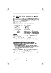
...adjust the parameters of "Share Memory", [Auto], will be designated as appropriate for details. 2. Click "Extend my Windows desktop onto this motherboard. E. With the internal onboard VGA and the external add-on the I/O panel of Multi Monitor feature. Connect the D-Sub monitor cable... benefits of this monitor". B. Right-click the display icon and select "Attached", if necessary. 2.5 Easy Multi Monitor Feature This motherboard supports Multi Monitor upgrade. When you have installed the onboard VGA driver already, there is less than the total capability of the ...
...adjust the parameters of "Share Memory", [Auto], will be designated as appropriate for details. 2. Click "Extend my Windows desktop onto this motherboard. E. With the internal onboard VGA and the external add-on the I/O panel of Multi Monitor feature. Connect the D-Sub monitor cable... benefits of this monitor". B. Right-click the display icon and select "Attached", if necessary. 2.5 Easy Multi Monitor Feature This motherboard supports Multi Monitor upgrade. When you have installed the onboard VGA driver already, there is less than the total capability of the ...

User Manual
Page 18
.... Placing jumper caps over these headers and connectors. Either end of SATA power cable to the power connector on the motherboard. 2.7 Onboard Headers and Connectors Onboard headers and connectors are NOT jumpers. Do NOT place jumper caps over the headers ...No. 5) (SATAII_3 (PORT 2.0): see p.10, No. 8) (SATAII_4 (PORT 2.1): see p.10 No. 19) Pin1 FLOPPY1 the red-striped side to the instruction of the motherboard! • Floppy Connector (33-pin FLOPPY1) (see p.10, No. 7) Serial ATA (SATA) Data Cable (Optional) SATAII_3 SATAII_1 (PORT 2.0) (PORT 1.0) SATAII_4 SATAII_2 (...
.... Placing jumper caps over these headers and connectors. Either end of SATA power cable to the power connector on the motherboard. 2.7 Onboard Headers and Connectors Onboard headers and connectors are NOT jumpers. Do NOT place jumper caps over the headers ...No. 5) (SATAII_3 (PORT 2.0): see p.10, No. 8) (SATAII_4 (PORT 2.1): see p.10 No. 19) Pin1 FLOPPY1 the red-striped side to the instruction of the motherboard! • Floppy Connector (33-pin FLOPPY1) (see p.10, No. 7) Serial ATA (SATA) Data Cable (Optional) SATAII_3 SATAII_1 (PORT 2.0) (PORT 1.0) SATAII_4 SATAII_2 (...
User Manual
Page 19
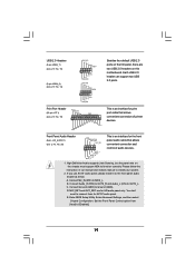
... don't need to Ground (GND). Each USB 2.0 header can support two USB 2.0 ports. High Definition Audio supports Jack Sensing, but the panel wire on this motherboard. E. MIC_RET and OUT_RET are two USB 2.0 headers on the chassis must support HDA to install your system. 2. Please follow the instruction in our manual and...
... don't need to Ground (GND). Each USB 2.0 header can support two USB 2.0 ports. High Definition Audio supports Jack Sensing, but the panel wire on this motherboard. E. MIC_RET and OUT_RET are two USB 2.0 headers on the chassis must support HDA to install your system. 2. Please follow the instruction in our manual and...
User Manual
Page 20
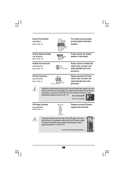
... 20 Please connect the chassis speaker to this connector and match the black wire to the ground pin. Please connect a chassis fan cable to this motherboard provides 4-Pin CPU fan (Quiet Fan) support, the 3-Pin CPU fan still can still work successfully even without the fan speed control function. System Panel... p.10 No. 15) Chassis Fan Connector (3-pin CHA_FAN1) (see p.10 No. 4) 12 24 Please connect an ATX power supply to this connector. 1 13 Though this motherboard, please connect it can work if you plan to connect the 3-Pin CPU fan to the CPU fan connector on this...
... 20 Please connect the chassis speaker to this connector and match the black wire to the ground pin. Please connect a chassis fan cable to this motherboard provides 4-Pin CPU fan (Quiet Fan) support, the 3-Pin CPU fan still can still work successfully even without the fan speed control function. System Panel... p.10 No. 15) Chassis Fan Connector (3-pin CHA_FAN1) (see p.10 No. 4) 12 24 Please connect an ATX power supply to this connector. 1 13 Though this motherboard, please connect it can work if you plan to connect the 3-Pin CPU fan to the CPU fan connector on this...

User Manual
Page 23
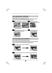
... Connect the SATA power cable to the SATA / SATAII hard disk. 2 . 1 0 Hot Plug and Hot Swap Functions for SATA / SATAII HDDs This motherboard supports Hot Plug and Hot Swap functions for the action to install the SATA / SATAII hard disks. STEP 4: Connect the other end of the SATA ... Plug Function? This section will guide you to insert and remove the SATA / SATAII HDDs while the system is still power-on this motherboard for the action to the motherboard's SATAII connector. If SATA / SATAII HDDs are NOT set for RAID configuration, it is called "Hot Plug" for SATA / SATAII Devices...
... Connect the SATA power cable to the SATA / SATAII hard disk. 2 . 1 0 Hot Plug and Hot Swap Functions for SATA / SATAII HDDs This motherboard supports Hot Plug and Hot Swap functions for the action to install the SATA / SATAII hard disks. STEP 4: Connect the other end of the SATA ... Plug Function? This section will guide you to insert and remove the SATA / SATAII HDDs while the system is still power-on this motherboard for the action to the motherboard's SATAII connector. If SATA / SATAII HDDs are NOT set for RAID configuration, it is called "Hot Plug" for SATA / SATAII Devices...
User Manual
Page 24
...driver is indicated in RAID mode. Before you process the Hot Plug: 1. The latest SATA / SATAII driver is available on our website: www.asrock.com 2. A. 7-pin SATA data cable B. Even some SATA / SATAII HDDs provide both SATA 15-pin power connector and IDE 1x4-pin ... the product spec on our support website: www.asrock.com 4. Below operation procedure is definitely not able to power supply Caution 1. The SATA / SATAII HDD, which are from our motherboard package. 5. Please follow below operation guide of our motherboard is installed into system properly. Without SATA 15-...
...driver is indicated in RAID mode. Before you process the Hot Plug: 1. The latest SATA / SATAII driver is available on our website: www.asrock.com 2. A. 7-pin SATA data cable B. Even some SATA / SATAII HDDs provide both SATA 15-pin power connector and IDE 1x4-pin ... the product spec on our support website: www.asrock.com 4. Below operation procedure is definitely not able to power supply Caution 1. The SATA / SATAII HDD, which are from our motherboard package. 5. Please follow below operation guide of our motherboard is installed into system properly. Without SATA 15-...
User Manual
Page 25
... Plug, improper procedure will cause the SATA / SATAII HDD damage and data loss. Step 1 Unplug SATA data cable from SATA / SATAII HDD side. 25 the motherboard's SATAII connector. SATA power cable 1x4-pin power connector (White) Step 3 Connect SATA 15-pin power cable connector (Black) end to the power supply 1x4...
... Plug, improper procedure will cause the SATA / SATAII HDD damage and data loss. Step 1 Unplug SATA data cable from SATA / SATAII HDD side. 25 the motherboard's SATAII connector. SATA power cable 1x4-pin power connector (White) Step 3 Connect SATA 15-pin power cable connector (Black) end to the power supply 1x4...


