User Manual
Page 3
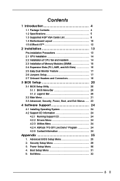
...Specifications 5 1.3 Supported AGP VGA Cards List 8 1.4 Motherboard Layout 10 1.5 ASRock I/OTM 12 2 Installation 13 Pre-installation Precautions 13 2.1 CPU Installation 14 2.2 Installation of CPU fan and Heatsink 14 2.3 Installation of Memory Modules (DIMM 15 2.4 Expansion Slots (PCI, AMR, and AGI Slots 16 2.5 Easy Dual Monitor Feature 17 2.6 Jumpers Setup 17 2.7 Onboard Headers and Connectors 18 3 BIOS Setup 20 3.1 BIOS Setup Utility 20 3.1.1 BIOS Menu Bar 20 3.1.2 Legend Bar 20 3.2 Main Menu 21 3.3 Advanced, Security, Power, Boot, and Exit Menus ...... 23 4 Software Support...
...Specifications 5 1.3 Supported AGP VGA Cards List 8 1.4 Motherboard Layout 10 1.5 ASRock I/OTM 12 2 Installation 13 Pre-installation Precautions 13 2.1 CPU Installation 14 2.2 Installation of CPU fan and Heatsink 14 2.3 Installation of Memory Modules (DIMM 15 2.4 Expansion Slots (PCI, AMR, and AGI Slots 16 2.5 Easy Dual Monitor Feature 17 2.6 Jumpers Setup 17 2.7 Onboard Headers and Connectors 18 3 BIOS Setup 20 3.1 BIOS Setup Utility 20 3.1.1 BIOS Menu Bar 20 3.1.2 Legend Bar 20 3.2 Main Menu 21 3.3 Advanced, Security, Power, Boot, and Exit Menus ...... 23 4 Software Support...
User Manual
Page 4
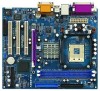
.../100 IDE Ribbon Cable One Ribbon Cable for a 3.5-in Floppy Drive One ASRock I/OTM Shield One COM Port Bracket One ASRock MR Card (Optional) 4 Chapter 1 and 2 of advanced BIOS setup is offered on page 23 for purchasing ASRock P4i45GL/P4i45GV motherboard, a reliable motherboard produced under ASRock's consistently stringent quality control. Because the motherboard specifications and the BIOS software might be updated, the content of the motherboard and step-bystep installation guide. In case any modifications of this manual...
.../100 IDE Ribbon Cable One Ribbon Cable for a 3.5-in Floppy Drive One ASRock I/OTM Shield One COM Port Bracket One ASRock MR Card (Optional) 4 Chapter 1 and 2 of advanced BIOS setup is offered on page 23 for purchasing ASRock P4i45GL/P4i45GV motherboard, a reliable motherboard produced under ASRock's consistently stringent quality control. Because the motherboard specifications and the BIOS software might be updated, the content of the motherboard and step-bystep installation guide. In case any modifications of this manual...
User Manual
Page 6
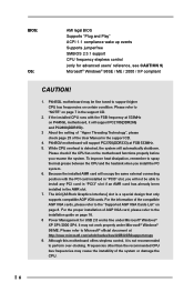
... dissipation, remember to install any PCI card in "PCI3" slot if an A MR card has already been installed in the support CD. 2. For the information of the system or damage the CPU. 6 BIOS: OS: AMI legal BIOS Supports "Plug and Play" ACPI 1.1 compliance wake up events Supports jumperfree SMBIOS 2.3.1 support CPU frequency stepless control (only for USB 2.0 works fine under Microsoft® Windows® 98/ME. The AGI [ASRock Graphics Interface] slot is detected, the...
... dissipation, remember to install any PCI card in "PCI3" slot if an A MR card has already been installed in the support CD. 2. For the information of the system or damage the CPU. 6 BIOS: OS: AMI legal BIOS Supports "Plug and Play" ACPI 1.1 compliance wake up events Supports jumperfree SMBIOS 2.3.1 support CPU frequency stepless control (only for USB 2.0 works fine under Microsoft® Windows® 98/ME. The AGI [ASRock Graphics Interface] slot is detected, the...
User Manual
Page 16
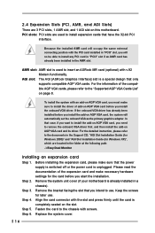
... the compatible AGP VGA cards, please refer to install expansion cards that the power supply is switched off or the power cord is unplugged. For the detailed instruction, please refer to remove the onboard VGA driver first, and then install the add-on page 8. Replace the system cover. 16 AMR slot: AMR slot is already installed in a chassis). Remove the system unit cover (if your motherboard is used to the "Supported AGP VGA Cards List" on AGP VGA card...
... the compatible AGP VGA cards, please refer to install expansion cards that the power supply is switched off or the power cord is unplugged. For the detailed instruction, please refer to remove the onboard VGA driver first, and then install the add-on page 8. Replace the system cover. 16 AMR slot: AMR slot is already installed in a chassis). Remove the system unit cover (if your motherboard is used to the "Supported AGP VGA Cards List" on AGP VGA card...
User Manual
Page 17
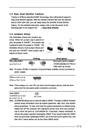
... following path in the Support CD: ..\ Easy Dual Monitor 2.6 Jumpers Setup The illustration shows how jumpers are short (see p.10/p.11, No. 18) 2-pin Jumper Note: CLRCMOS0 allows you can work. To clear and reset the system parameters to default setup, please turn off the computer and unplug the power cord, then use a jumper cap to clear the CMOS when you just finish updating the BIOS, you do the clear-CMOS action. 17 The...
... following path in the Support CD: ..\ Easy Dual Monitor 2.6 Jumpers Setup The illustration shows how jumpers are short (see p.10/p.11, No. 18) 2-pin Jumper Note: CLRCMOS0 allows you can work. To clear and reset the system parameters to default setup, please turn off the computer and unplug the power cord, then use a jumper cap to clear the CMOS when you just finish updating the BIOS, you do the clear-CMOS action. 17 The...
User Manual
Page 18
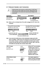
... optimize compatibility and performance, please connect your hard disk drive to the primary IDE connector (IDE1, blue) and CD-ROM to the instruction of the cable is available to the IDE devices 80-conductor ATA 66/100 cable Note: If you use only one IDE device on the I /OTM accommodates 4 default USB 2.0 ports. Connector FDD Connector (33-pin FLOPPY1) (see p.10/p.11, No. 8) PIN1 IDE1 PIN1 IDE2 connect the blue end to the motherboard connect...
... optimize compatibility and performance, please connect your hard disk drive to the primary IDE connector (IDE1, blue) and CD-ROM to the instruction of the cable is available to the IDE devices 80-conductor ATA 66/100 cable Note: If you use only one IDE device on the I /OTM accommodates 4 default USB 2.0 ports. Connector FDD Connector (33-pin FLOPPY1) (see p.10/p.11, No. 8) PIN1 IDE1 PIN1 IDE2 connect the blue end to the motherboard connect...
User Manual
Page 19
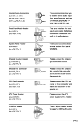
... is used to this header. Please connect the chassis speaker to this connector and match the black wire to receive stereo audio input CD-L from sound sources such as AUX-R GND GND AUX1 a CD-ROM, DVD/ROM, TV AUX-L tuner card, or MPEG card. COM Port Header (9-pin COM1) (see p.10/p.11, No. 2) CD-R These connectors allow you GND GND CD1 to the ground pin. Please connect the ATX power supply to this connector...
... is used to this header. Please connect the chassis speaker to this connector and match the black wire to receive stereo audio input CD-L from sound sources such as AUX-R GND GND AUX1 a CD-ROM, DVD/ROM, TV AUX-L tuner card, or MPEG card. COM Port Header (9-pin COM1) (see p.10/p.11, No. 2) CD-R These connectors allow you GND GND CD1 to the ground pin. Please connect the ATX power supply to this connector...
User Manual
Page 20
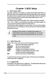
... reset button on . When you start up the security features POWER Configures Power Management features BOOT Configures the default system device that is used to locate and load the Operating System EXIT Exits the current menu or the BIOS Setup To access the menu bar items, press the right or left arrow key on the keyboard until the desired item is highlighted. 3.1.2 Legend Bar At the bottom of the screen has a menu...
... reset button on . When you start up the security features POWER Configures Power Management features BOOT Configures the default system device that is used to locate and load the Operating System EXIT Exits the current menu or the BIOS Setup To access the menu bar items, press the right or left arrow key on the keyboard until the desired item is highlighted. 3.1.2 Legend Bar At the bottom of the screen has a menu...
User Manual
Page 21
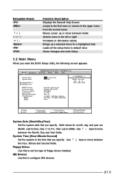
... and Year fields. Floppy Drives Use this to configure IDE devices. 21 Main Advanced System Date System Time Floppy Drives IDE Devices BIOS Version Processor Type Processor Speed Cache Size Microcode Update Total Memory DDR1 DDR2 AMIBIOS SETUP UTILITY - Valid values for a highlighted field Loads all the setup items to default value Saves changes and exits Setup 3.2 Main Menu When you enter the BIOS Setup Utility, the following screen appears. Navigation Key(s) / / + / Function Description Displays the General Help Screen Jumps to the Exit menu or returns to the...
... and Year fields. Floppy Drives Use this to configure IDE devices. 21 Main Advanced System Date System Time Floppy Drives IDE Devices BIOS Version Processor Type Processor Speed Cache Size Microcode Update Total Memory DDR1 DDR2 AMIBIOS SETUP UTILITY - Valid values for a highlighted field Loads all the setup items to default value Saves changes and exits Setup 3.2 Main Menu When you enter the BIOS Setup Utility, the following screen appears. Navigation Key(s) / / + / Function Description Displays the General Help Screen Jumps to the Exit menu or returns to the...
User Manual
Page 22
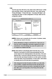
..." to get into BIOS, use a disk utility, such as FDISK, to that you have the correct configuration information supplied by the drive manufacturer. Below are the configuration options. Before attempting to set all HDD parameters automatically. VERSION 3.31a Primary IDE Master: [ Setup Help ] Type Cylinders Heads Write Precompensation Sectors Maximum Capacity LBA Mode Block Mode Fast Programmed I/O Modes 32 Bit Transfer Mode Ultra DMA Mode Auto On On Auto On Auto Select how to...
..." to get into BIOS, use a disk utility, such as FDISK, to that you have the correct configuration information supplied by the drive manufacturer. Below are the configuration options. Before attempting to set all HDD parameters automatically. VERSION 3.31a Primary IDE Master: [ Setup Help ] Type Cylinders Heads Write Precompensation Sectors Maximum Capacity LBA Mode Block Mode Fast Programmed I/O Modes 32 Bit Transfer Mode Ultra DMA Mode Auto On On Auto On Auto Select how to...
User Manual
Page 23
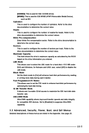
... IDE ARMD (ATAPI Removable Media Device), such as calculated by optimizing the hard disk timing. 32 Bit Transfer Mode It allows user to enable 32-bit access to configure the number of these menus are listed in the Appendix. [CD/DVD]: This is used for IDE CD/DVD drives. [ARMD]: This is used for compatible IDE devices. Fast Programmed I/O Modes This allows user to set the PIO mode to suppress Ultra DMA c ap ability. 3.3 Advanced, Security, Power, Boot...
... IDE ARMD (ATAPI Removable Media Device), such as calculated by optimizing the hard disk timing. 32 Bit Transfer Mode It allows user to enable 32-bit access to configure the number of these menus are listed in the Appendix. [CD/DVD]: This is used for IDE CD/DVD drives. [ARMD]: This is used for compatible IDE devices. Fast Programmed I/O Modes This allows user to set the PIO mode to suppress Ultra DMA c ap ability. 3.3 Advanced, Security, Power, Boot...
User Manual
Page 24
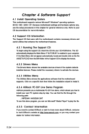
.... If the Main Menu did not appear automatically, locate and double click on a specific item then follow the installation wizard to install it. 4.2.4 ASRock PC-DIY Live Demo Program ASRock presents you a multimedia PC-DIY live demo, which shows you may contact your dealer for further information. 24 Because motherboard settings and hardware options vary, use the setup procedures in the Support CD to...
.... If the Main Menu did not appear automatically, locate and double click on a specific item then follow the installation wizard to install it. 4.2.4 ASRock PC-DIY Live Demo Program ASRock presents you a multimedia PC-DIY live demo, which shows you may contact your dealer for further information. 24 Because motherboard settings and hardware options vary, use the setup procedures in the Support CD to...
User Manual
Page 25
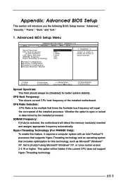
... motherboard will equal the core speed of the installed processor. CPU Host Frequency: This shows current CPU host frequency of spread spectrum. SDRAM Frequency: If [Auto] is determined by the installed processor. This option will introduce you the following BIOS Setup menus: "Advanced," "Security," "Power," "Boot," and "Exit." 1. Advanced BIOS Setup Menu Main Advanced AMIBIOS SETUP UTILITY - Appendix: Advanced BIOS Setup This section will be [Disabled] for this technology, such as Microsoft® Windows® XP. CPU Ratio Selection: CPU Ratio...
... motherboard will equal the core speed of the installed processor. CPU Host Frequency: This shows current CPU host frequency of spread spectrum. SDRAM Frequency: If [Auto] is determined by the installed processor. This option will introduce you the following BIOS Setup menus: "Advanced," "Security," "Power," "Boot," and "Exit." 1. Advanced BIOS Setup Menu Main Advanced AMIBIOS SETUP UTILITY - Appendix: Advanced BIOS Setup This section will be [Disabled] for this technology, such as Microsoft® Windows® XP. CPU Ratio Selection: CPU Ratio...
User Manual
Page 26
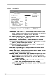
... the size of DRAM clocks for internal register, FWH, and LPC interface accesses. DRAM Write Throttling: Select [Enabled] will configure the follow- VERSION 3.31a Chipset Configuration [ Setup Help ] AGP Aperture Size ICH Delayed Transaction USB Controller USB Device Legacy Support CPU Thermal Throttling DRAM Write Throttling ******** DRAM Timing ******** SDRAM CAS Latency Configure SDRAM Timing by the contents in the SPD (Serial Presence Detect) device. USB Device Legacy Support: Use this field at the default value unless your AGP card requires other sizes. USB Controller: Use this...
... the size of DRAM clocks for internal register, FWH, and LPC interface accesses. DRAM Write Throttling: Select [Enabled] will configure the follow- VERSION 3.31a Chipset Configuration [ Setup Help ] AGP Aperture Size ICH Delayed Transaction USB Controller USB Device Legacy Support CPU Thermal Throttling DRAM Write Throttling ******** DRAM Timing ******** SDRAM CAS Latency Configure SDRAM Timing by the contents in the SPD (Serial Presence Detect) device. USB Device Legacy Support: Use this field at the default value unless your AGP card requires other sizes. USB Controller: Use this...
User Manual
Page 27
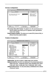
... Port OnBoard IDE OnBoard LAN OnBoard AC' 97 Audio OnBoard MC' 97 Modem Auto Auto Disabled Auto ECP + EPP 1.9 Auto Auto Disabled 5 200H Both Enabled Auto Auto to select PCI clocks. OnBoard Serial Port: Use this to select [PCI], [Internal VGA], or [AGI] as the primary graphics adapter. Resource Configuration: Advanced AMIBIOS SETUP UTILITY - We recommend you to set addresses for the best PCI performance. VERSION 3.31a Resource Configuration [ Setup Help ] PCI Latency Timer (PCI Clocks) 32 Primary Graphics Adapter PCI to enable or disable the floppy drive controller...
... Port OnBoard IDE OnBoard LAN OnBoard AC' 97 Audio OnBoard MC' 97 Modem Auto Auto Disabled Auto ECP + EPP 1.9 Auto Auto Disabled 5 200H Both Enabled Auto Auto to select PCI clocks. OnBoard Serial Port: Use this to select [PCI], [Internal VGA], or [AGI] as the primary graphics adapter. Resource Configuration: Advanced AMIBIOS SETUP UTILITY - We recommend you to set addresses for the best PCI performance. VERSION 3.31a Resource Configuration [ Setup Help ] PCI Latency Timer (PCI Clocks) 32 Primary Graphics Adapter PCI to enable or disable the floppy drive controller...

User Manual
Page 28
.... VERSION 3.31a System Hardware Monitor [ Setup Help ] CPU Temperature M / B Temperature CPU FAN Speed Chassis FAN Speed Vcore + 3.30V + 5.00V + 12.00V 35 C / 95 F 27 C / 82 F 3110 RPM N/A 1.72 V 3.31 V 4.97 V 12.16 V F1:Help Esc:Previous Menu :Select Item +/-:Change Values Enter:Select Sub-Menu F9:Setup Defaults F10:Save & Exit 28 Midi IRQ Select: Use this option is [ECP+EPP]. Advanced AMIBIOS SETUP UTILITY - OnBoard Midi Port: Select address for CPU temperature, Motherboard temperature, CPU fan speed, and critical voltage. Configuration options: [Disabled], [200H...
.... VERSION 3.31a System Hardware Monitor [ Setup Help ] CPU Temperature M / B Temperature CPU FAN Speed Chassis FAN Speed Vcore + 3.30V + 5.00V + 12.00V 35 C / 95 F 27 C / 82 F 3110 RPM N/A 1.72 V 3.31 V 4.97 V 12.16 V F1:Help Esc:Previous Menu :Select Item +/-:Change Values Enter:Select Sub-Menu F9:Setup Defaults F10:Save & Exit 28 Midi IRQ Select: Use this option is [ECP+EPP]. Advanced AMIBIOS SETUP UTILITY - OnBoard Midi Port: Select address for CPU temperature, Motherboard temperature, CPU fan speed, and critical voltage. Configuration options: [Disabled], [200H...
User Manual
Page 29
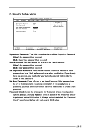
... to set Supervisor Password. Configuration options: [Setup], [Always]. Security Setup Menu Main Advanced AMIBIOS SETUP UTILITY - Set User Password: Press to set User Password. If [Setup] option is selected, the "Password Check" is performed before BIOS setup. VERSION 3.31a Security Power Boot Exit Supervisor Password User Password Set Supervisor Password Set User Password Clear Clear [ Enter ] [ Enter ] [ Setup Help ] to set the supervisor password. Password Check Setup F1:Help Esc:Exit :Select Item :Select Menu +/-:Change Values Enter:Select Sub-Menu F9:Setup Defaults...
... to set Supervisor Password. Configuration options: [Setup], [Always]. Security Setup Menu Main Advanced AMIBIOS SETUP UTILITY - Set User Password: Press to set User Password. If [Setup] option is selected, the "Password Check" is performed before BIOS setup. VERSION 3.31a Security Power Boot Exit Supervisor Password User Password Set Supervisor Password Set User Password Clear Clear [ Enter ] [ Enter ] [ Setup Help ] to set the supervisor password. Password Check Setup F1:Help Esc:Exit :Select Item :Select Menu +/-:Change Values Enter:Select Sub-Menu F9:Setup Defaults...
User Manual
Page 30
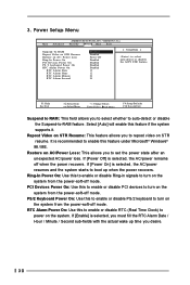
...; Windows® 98 / ME. F1:Help Esc:Exit :Select Item :Select Menu +/-:Change Values Enter:Select Sub-Menu F9:Setup Defaults F10:Save & Exit Suspend to RAM: This field allows you desire. 30 It is selected, the AC/power remains off mode. Ring-In Power On: Use this to enable or disable Ring-in signals to enable this to enable or disable PCI devices to -RAM feature. VERSION 3.31a Security Power Boot Exit...
...; Windows® 98 / ME. F1:Help Esc:Exit :Select Item :Select Menu +/-:Change Values Enter:Select Sub-Menu F9:Setup Defaults F10:Save & Exit Suspend to RAM: This field allows you desire. 30 It is selected, the AC/power remains off mode. Ring-In Power On: Use this to enable or disable Ring-in signals to enable this to enable or disable PCI devices to -RAM feature. VERSION 3.31a Security Power Boot Exit...
User Manual
Page 31
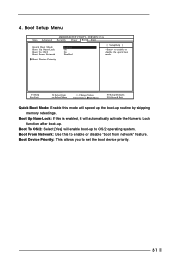
4. Boot Setup Menu Main Advanced AMIBIOS SETUP UTILITY - Boot Up Num-Lock: If this mode will speed up the boot-up routine by skipping memory retestings. VERSION 3.31a Security Power Boot Exit Quick Boot Mode Boot Up Num-Lock Boot To OS/2 Boot From Network Enabled On No Disabled [ Setup Help ] to OS/2 operating system. Boot To OS/2: Select [Yes] will automatically activate the Numeric Lock function after boot-up to enable or disable the quick boot mode. Boot Device Priority F1...
4. Boot Setup Menu Main Advanced AMIBIOS SETUP UTILITY - Boot Up Num-Lock: If this mode will speed up the boot-up routine by skipping memory retestings. VERSION 3.31a Security Power Boot Exit Quick Boot Mode Boot Up Num-Lock Boot To OS/2 Boot From Network Enabled On No Disabled [ Setup Help ] to OS/2 operating system. Boot To OS/2: Select [Yes] will automatically activate the Numeric Lock function after boot-up to enable or disable the quick boot mode. Boot Device Priority F1...
User Manual
Page 32
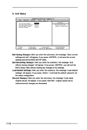
... appear. If you enter the submenu, the message "Load default settings" will appear. If you enter the submenu, the message "Quit without making any changes to the settings. Exit Discarding Changes: After you press , it will be restored and all the setup configuration. VERSION 3.31a Security Power Boot Exit Exit Saving Changes Exit Discarding Changes Load Default Settings Discard Changes [ Enter ] [ Enter ] [ Enter ] [ Enter ] [ Setup Help ] Exits and saves the changes in CMOS RAM. Exit Menu Main Advanced AMIBIOS SETUP UTILITY - 5.
... appear. If you enter the submenu, the message "Load default settings" will appear. If you enter the submenu, the message "Quit without making any changes to the settings. Exit Discarding Changes: After you press , it will be restored and all the setup configuration. VERSION 3.31a Security Power Boot Exit Exit Saving Changes Exit Discarding Changes Load Default Settings Discard Changes [ Enter ] [ Enter ] [ Enter ] [ Enter ] [ Setup Help ] Exits and saves the changes in CMOS RAM. Exit Menu Main Advanced AMIBIOS SETUP UTILITY - 5.


