
User Manual
Page 10
... to perform over-clocking. ASRock website: http://www.asrock.com/Feature/ SmartView/index..... 13. ASRock website: http://www.asrock.com/Feature/...iPad Touch, ASRock has prepared a...ASRock of the system or damage the CPU. 12. Connecting your computer and up -do-date supported games! ASRock... used. 10 ASRock motherboards are exclusively equipped with...-go. ASRock website: http://www.asrock.com/Feature...ASRock AIWI utility introduces a new way of cial website or ASRock software support CD to your motherboard, and also download the free AIWI Lite from ASRock... install the ASRock AIWI utility ...
... to perform over-clocking. ASRock website: http://www.asrock.com/Feature/ SmartView/index..... 13. ASRock website: http://www.asrock.com/Feature/...iPad Touch, ASRock has prepared a...ASRock of the system or damage the CPU. 12. Connecting your computer and up -do-date supported games! ASRock... used. 10 ASRock motherboards are exclusively equipped with...-go. ASRock website: http://www.asrock.com/Feature...ASRock AIWI utility introduces a new way of cial website or ASRock software support CD to your motherboard, and also download the free AIWI Lite from ASRock... install the ASRock AIWI utility ...

User Manual
Page 12
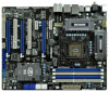
... CHA_FAN1 CMOS Battery Top: LINE IN Center: Bottom: MIC IN LAN PHY USB 3.0 CHA_FAN3 CHA_FAN2 PCIE1 P67 Extreme4 PCIE2 1394a PCIE3 PCI Express 2.0 Super I/O PCI1 RoHS PCIE4 1 CLRCMOS1 Intel P67 64Mb BIOS SATA2_4_5 SATA2_2_3 AUDIO CODEC HD_AUDIO1 1 HDMI_SPDIF1 COM1 1 1 PCI2 ErP/EuP Ready Front USB 3.0... 22 23 35 34 33 32 31 30 29 28 27 26 25 24 1 ATX 12V Power Connector (ATX12V1) 2 Power Fan Connector (PWR_FAN1) 3 1155-Pin CPU Socket 4 CPU Fan Connector (CPU_FAN1) 5 CPU Fan Connector (CPU_FAN2) 6 2 x 240-pin DDR3 DIMM Slots (Dual Channel: DDR3_A1, DDR3_B1, Blue) 7...
... CHA_FAN1 CMOS Battery Top: LINE IN Center: Bottom: MIC IN LAN PHY USB 3.0 CHA_FAN3 CHA_FAN2 PCIE1 P67 Extreme4 PCIE2 1394a PCIE3 PCI Express 2.0 Super I/O PCI1 RoHS PCIE4 1 CLRCMOS1 Intel P67 64Mb BIOS SATA2_4_5 SATA2_2_3 AUDIO CODEC HD_AUDIO1 1 HDMI_SPDIF1 COM1 1 1 PCI2 ErP/EuP Ready Front USB 3.0... 22 23 35 34 33 32 31 30 29 28 27 26 25 24 1 ATX 12V Power Connector (ATX12V1) 2 Power Fan Connector (PWR_FAN1) 3 1155-Pin CPU Socket 4 CPU Fan Connector (CPU_FAN1) 5 CPU Fan Connector (CPU_FAN2) 6 2 x 240-pin DDR3 DIMM Slots (Dual Channel: DDR3_A1, DDR3_B1, Blue) 7...

User Manual
Page 16
...cap tab to handle and avoid kicking off the PnP cap. 2. Load Plate Load Lever Contact Array Socket Body 1155-Pin Socket Overview Before you insert the 1155-Pin CPU into the socket if above situation is found. Otherwise, the CPU will be placed if returning the motherboard for after ...Step 2. Remove PnP Cap (Pick and Place Cap). 1. This cap must be seriously damaged. Step 1-3. Open the socket: Step 1-1. 2.3 CPU Installation For the installation of Intel 1155-Pin CPU, please follow the steps below. Do not force to fully open position at approximately 100 degrees. Disengaging the...
...cap tab to handle and avoid kicking off the PnP cap. 2. Load Plate Load Lever Contact Array Socket Body 1155-Pin Socket Overview Before you insert the 1155-Pin CPU into the socket if above situation is found. Otherwise, the CPU will be placed if returning the motherboard for after ...Step 2. Remove PnP Cap (Pick and Place Cap). 1. This cap must be seriously damaged. Step 1-3. Open the socket: Step 1-1. 2.3 CPU Installation For the installation of Intel 1155-Pin CPU, please follow the steps below. Do not force to fully open position at approximately 100 degrees. Disengaging the...

User Manual
Page 17
... the load plate onto the IHS. black line Step 3-2. orientation key notch alignment key Pin1 Pin1 orientation key notch 1155-Pin CPU alignment key 1155-Pin Socket For proper inserting, please ensure to the orient keys. Verify that the CPU is marked with black line. Step 4. While pressing down lightly on load ...
... the load plate onto the IHS. black line Step 3-2. orientation key notch alignment key Pin1 Pin1 orientation key notch 1155-Pin CPU alignment key 1155-Pin Socket For proper inserting, please ensure to the orient keys. Verify that the CPU is marked with black line. Step 4. While pressing down lightly on load ...

User Manual
Page 18
...cannot be noticed that this motherboard supports Combo Cooler Option (C.C.O.), which provides the exible option to illustrate the installation of the heatsink for Socket LGA 1155/1156 CPU fan. 18 Step 5. Please be secured on fastener caps with thumb to MB header Fastener slots pointing straight out Press ... material between the CPU and the heatsink to the CPU_FAN connector (CPU_FAN1, see page 12, No. 4). Below is equipped with 1155-Pin socket that the CPU and the heatsink are securely fastened and in good contact with each other components. Secure excess cable with tie-wrap...
...cannot be noticed that this motherboard supports Combo Cooler Option (C.C.O.), which provides the exible option to illustrate the installation of the heatsink for Socket LGA 1155/1156 CPU fan. 18 Step 5. Please be secured on fastener caps with thumb to MB header Fastener slots pointing straight out Press ... material between the CPU and the heatsink to the CPU_FAN connector (CPU_FAN1, see page 12, No. 4). Below is equipped with 1155-Pin socket that the CPU and the heatsink are securely fastened and in good contact with each other components. Secure excess cable with tie-wrap...

Quick Installation Guide
Page 2
... 21 22 23 35 34 33 32 31 30 29 28 27 26 25 24 1 ATX 12V Power Connector (ATX12V1) 2 Power Fan Connector (PWR_FAN1) 3 1155-Pin CPU Socket 4 CPU Fan Connector (CPU_FAN1) 5 CPU Fan Connector (CPU_FAN2) 6 2 x 240-pin DDR3 DIMM Slots (Dual Channel: DDR3_A1, DDR3_B1, Blue) 7 2 x 240-pin DDR3 DIMM Slots (Dual... Slot (PCIE2, Blue) 43 PCI Express 2.0 x1 Slot (PCIE1, White) 44 SLI / XFIRE Power Connector 45 Chassis Fan Connector (CHA_FAN3) 46 Chassis Fan Connector (CHA_FAN2) 2 ASRock P67 Extreme4 Motherboard English
... 21 22 23 35 34 33 32 31 30 29 28 27 26 25 24 1 ATX 12V Power Connector (ATX12V1) 2 Power Fan Connector (PWR_FAN1) 3 1155-Pin CPU Socket 4 CPU Fan Connector (CPU_FAN1) 5 CPU Fan Connector (CPU_FAN2) 6 2 x 240-pin DDR3 DIMM Slots (Dual Channel: DDR3_A1, DDR3_B1, Blue) 7 2 x 240-pin DDR3 DIMM Slots (Dual... Slot (PCIE2, Blue) 43 PCI Express 2.0 x1 Slot (PCIE1, White) 44 SLI / XFIRE Power Connector 45 Chassis Fan Connector (CHA_FAN3) 46 Chassis Fan Connector (CHA_FAN2) 2 ASRock P67 Extreme4 Motherboard English

Quick Installation Guide
Page 10
...to RAM (S3), hibernation mode (S4) or power off (S5). ASRock website: http://www.asrock.com/Feature/ SmartView/index.asp 11. ASRock APP Charger allows you can be used. 10 ASRock P67 Extreme4 Motherboard English ASRock website: http://www.asrock.com/Feature/AppCharger/index.asp 10. Combo Cooler Option (C.C.O.) provides the .... Frequencies other than ever. To experience intuitive motion controlled games is just to adopt three different CPU cooler types, Socket LGA 775, LGA 1155 and LGA 1156. Please be noticed that not all the 775 and 1156 CPU Fan can easily enjoy the marvelous...
...to RAM (S3), hibernation mode (S4) or power off (S5). ASRock website: http://www.asrock.com/Feature/ SmartView/index.asp 11. ASRock APP Charger allows you can be used. 10 ASRock P67 Extreme4 Motherboard English ASRock website: http://www.asrock.com/Feature/AppCharger/index.asp 10. Combo Cooler Option (C.C.O.) provides the .... Frequencies other than ever. To experience intuitive motion controlled games is just to adopt three different CPU cooler types, Socket LGA 775, LGA 1155 and LGA 1156. Please be noticed that not all the 775 and 1156 CPU Fan can easily enjoy the marvelous...

Quick Installation Guide
Page 12
...damaged. Load Plate Contact Array Load Lever Socket Body 1155-Pin Socket Overview Before you install motherboard components or change any bent pin on the socket. Doing so may cause severe damage to secure the moth- English 12 ASRock P67 Extreme4 Motherboard To avoid damaging the motherboard components ... comes with the component. 5. Whenever you handle components. 3. Unplug the power cord from the wall socket before you insert the 1155-Pin CPU into the socket, please check if the CPU surface is unclean or if there is found. Installation Pre-installation Precautions ...
...damaged. Load Plate Contact Array Load Lever Socket Body 1155-Pin Socket Overview Before you install motherboard components or change any bent pin on the socket. Doing so may cause severe damage to secure the moth- English 12 ASRock P67 Extreme4 Motherboard To avoid damaging the motherboard components ... comes with the component. 5. Whenever you handle components. 3. Unplug the power cord from the wall socket before you insert the 1155-Pin CPU into the socket, please check if the CPU surface is unclean or if there is found. Installation Pre-installation Precautions ...

Quick Installation Guide
Page 13
... Pin1 Pin1 orientation key notch 1155-Pin CPU alignment key 1155-Pin Socket For proper inserting, please ensure to fully open position at approximately 100 degrees. Rotate the load plate to match the two orientation key notches of the CPU with the two alignment keys of the socket. 13 ASRock P67 Extreme4 Motherboard English Step 3. Hold the... at approximately 135 degrees. Remove PnP Cap (Pick and Place Cap). 1. This cap must be placed if returning the motherboard for after service. Open the socket: Step 1-1.
... Pin1 Pin1 orientation key notch 1155-Pin CPU alignment key 1155-Pin Socket For proper inserting, please ensure to fully open position at approximately 100 degrees. Rotate the load plate to match the two orientation key notches of the CPU with the two alignment keys of the socket. 13 ASRock P67 Extreme4 Motherboard English Step 3. Hold the... at approximately 135 degrees. Remove PnP Cap (Pick and Place Cap). 1. This cap must be placed if returning the motherboard for after service. Open the socket: Step 1-1.

Quick Installation Guide
Page 14
... ensure cable does not interfere with thumb to the orient keys. Connect fan header with tie-wrap to illustrate the installation of the heatsink for Socket LGA 1155/1156 CPU fan. 14 ASRock P67 Extreme4 Motherboard English Secure excess cable with the CPU fan connector on side closest to adopt three different CPU cooler types...
... ensure cable does not interfere with thumb to the orient keys. Connect fan header with tie-wrap to illustrate the installation of the heatsink for Socket LGA 1155/1156 CPU fan. 14 ASRock P67 Extreme4 Motherboard English Secure excess cable with the CPU fan connector on side closest to adopt three different CPU cooler types...

Quick Installation Guide
Page 212
2 1 2 3 IC 4 5 2.1 CPU 설치 Intel 1155 핀 CPU 장착판 Load Plate Load Lever Contact Array Socket Body 1155 1155 핀 CPU CPU CPU CPU 한 국 어 212 ASRock P67 Extreme4 Motherboard
2 1 2 3 IC 4 5 2.1 CPU 설치 Intel 1155 핀 CPU 장착판 Load Plate Load Lever Contact Array Socket Body 1155 1155 핀 CPU CPU CPU CPU 한 국 어 212 ASRock P67 Extreme4 Motherboard

Quick Installation Guide
Page 238
IC 4. 2.1 CPU Intel 1155-LAND CPU Load Plate Load Lever Contact Array Socket Body 1155 1155-LAND CPU CPU CPU CPU 1 1-1 日本語 238 ASRock P67 Extreme4 Motherboard 1. 2. 3.
IC 4. 2.1 CPU Intel 1155-LAND CPU Load Plate Load Lever Contact Array Socket Body 1155 1155-LAND CPU CPU CPU CPU 1 1-1 日本語 238 ASRock P67 Extreme4 Motherboard 1. 2. 3.

Quick Installation Guide
Page 240
4 4-1 HIS 4-2 4-3 2.2 CPU CPU 以下は、1155-LAND CPU 1 HIS Apply Thermal Interface Material 2 CPU_FAN1、2 No. 4 CPU 3 4 Fan cables on side closest to MB header Fastener slots pointing straight out Press Down (4 Places) 5 CPU 6 C.C.O Socket LGA 775、LGA 1155 と LGA 1156 の 3 CPU Socket LGA 1155/1156 CPU 日本語 240 ASRock P67 Extreme4 Motherboard
4 4-1 HIS 4-2 4-3 2.2 CPU CPU 以下は、1155-LAND CPU 1 HIS Apply Thermal Interface Material 2 CPU_FAN1、2 No. 4 CPU 3 4 Fan cables on side closest to MB header Fastener slots pointing straight out Press Down (4 Places) 5 CPU 6 C.C.O Socket LGA 775、LGA 1155 と LGA 1156 の 3 CPU Socket LGA 1155/1156 CPU 日本語 240 ASRock P67 Extreme4 Motherboard

Quick Installation Guide
Page 262
2 安全防范 1 2 3 4 5 2.1 CPU 安裝 要安裝 Intel 1155 針 CPU Load Plate Contact Array Load Lever Socket Body 1155 在您將 1155 針 CPU CPU CPU CPU 步驟 1. 1-1 簡體中文 262 ASRock P67 Extreme4 Motherboard
2 安全防范 1 2 3 4 5 2.1 CPU 安裝 要安裝 Intel 1155 針 CPU Load Plate Contact Array Load Lever Socket Body 1155 在您將 1155 針 CPU CPU CPU CPU 步驟 1. 1-1 簡體中文 262 ASRock P67 Extreme4 Motherboard

Quick Installation Guide
Page 287
2 安全防範 1 2 3 4 5 2.1 CPU 安裝 要安裝 Intel 1155 針 CPU Load Plate Contact Array Load Lever Socket Body ( 插槽 ) 1155 在您將 1155 針 CPU CPU CPU CPU 步驟 1. 1-1 繁體中文 287 ASRock P67 Extreme4 Motherboard
2 安全防範 1 2 3 4 5 2.1 CPU 安裝 要安裝 Intel 1155 針 CPU Load Plate Contact Array Load Lever Socket Body ( 插槽 ) 1155 在您將 1155 針 CPU CPU CPU CPU 步驟 1. 1-1 繁體中文 287 ASRock P67 Extreme4 Motherboard