Quick Installation Guide
Page 1
...damages (including damages for loss of profits, loss of business, loss of data, interruption of business and the like), even if ASRock has been advised of the possibility of their respective companies, and are furnished for informational use only and subject to the implied warranties... "Perchlorate Material-special handling may cause undesired operation. Products and corporate names appearing in this documentation may or may appear in this motherboard contains Perchlorate, a toxic substance controlled in any form or by any kind, either expressed or implied, including but not limited to...
...damages (including damages for loss of profits, loss of business, loss of data, interruption of business and the like), even if ASRock has been advised of the possibility of their respective companies, and are furnished for informational use only and subject to the implied warranties... "Perchlorate Material-special handling may cause undesired operation. Products and corporate names appearing in this documentation may or may appear in this motherboard contains Perchlorate, a toxic substance controlled in any form or by any kind, either expressed or implied, including but not limited to...

Quick Installation Guide
Page 5
Motherboard Layout TRX40 Creator M2_1 M2_2 DDR4_D2 (64 bit, 288-pin module) DDR4_D1 (64 bit, 288-pin module) DDR4_C2 (64 bit, 288-pin module) DDR4_C1 (64 bit, 288-pin module) TRX40 CREATOR DDR4_A1 (64 bit, 288-pin module) DDR4_A2 (64 bit,... T: USB1 10GLAN (AQUANTIA B: USB2 AQC107) M2_4 CHA_FAN1/WP PCIE1 CPU_FAN2/WP PCIE2 PCIE3 CPU_FAN1 ATX12V1 ADDR_LED2 1 F_USB32G2_TC_1 RGB_LED2 1 1 AMD TRX40 SATA3_5_6 SATA3_7_8 USB32G1_7_8 SATA3_3_4 SATA3_1_2 M2_3 GFX_12V1 HD_AUDIO1 HD_AUDIO_RA1 1 1 PCIE4 TPMS1 1 ADDR_LED1 1 CHA_FAN3 CHA_FAN2 /WP /WP SPK_PLED1 RGB_LED1 1 1 ...
Motherboard Layout TRX40 Creator M2_1 M2_2 DDR4_D2 (64 bit, 288-pin module) DDR4_D1 (64 bit, 288-pin module) DDR4_C2 (64 bit, 288-pin module) DDR4_C1 (64 bit, 288-pin module) TRX40 CREATOR DDR4_A1 (64 bit, 288-pin module) DDR4_A2 (64 bit,... T: USB1 10GLAN (AQUANTIA B: USB2 AQC107) M2_4 CHA_FAN1/WP PCIE1 CPU_FAN2/WP PCIE2 PCIE3 CPU_FAN1 ATX12V1 ADDR_LED2 1 F_USB32G2_TC_1 RGB_LED2 1 1 AMD TRX40 SATA3_5_6 SATA3_7_8 USB32G1_7_8 SATA3_3_4 SATA3_1_2 M2_3 GFX_12V1 HD_AUDIO1 HD_AUDIO_RA1 1 1 PCIE4 TPMS1 1 ADDR_LED1 1 CHA_FAN3 CHA_FAN2 /WP /WP SPK_PLED1 RGB_LED1 1 1 ...
Quick Installation Guide
Page 9
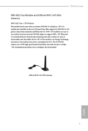
Bluetooth v5.0 standard features Smart Ready technology that offers support for PCs. ASRock WiFi 2.4/5 GHz Antenna 5 English WiFi + BT module is an easy-touse wireless local area network (WLAN) adapter to the environment. BT 5.0 also includes Low Energy ... and offers max link rate up to 2.4Gbps. * The transmission speed may vary according to support WiFi + BT. TRX40 Creator WiFi-802.11ax Module and ASRock WiFi 2.4/5 GHz Antenna WiFi-802.11ax + BT Module This motherboard comes with an exclusive WiFi 802.11 a/b/g/n/ax + BT v5.0 module (pre-installed on the rear I/O panel) that...
Bluetooth v5.0 standard features Smart Ready technology that offers support for PCs. ASRock WiFi 2.4/5 GHz Antenna 5 English WiFi + BT module is an easy-touse wireless local area network (WLAN) adapter to the environment. BT 5.0 also includes Low Energy ... and offers max link rate up to 2.4Gbps. * The transmission speed may vary according to support WiFi + BT. TRX40 Creator WiFi-802.11ax Module and ASRock WiFi 2.4/5 GHz Antenna WiFi-802.11ax + BT Module This motherboard comes with an exclusive WiFi 802.11 a/b/g/n/ax + BT v5.0 module (pre-installed on the rear I/O panel) that...

Quick Installation Guide
Page 10
... x 1.65-in, 3.7 cm x 4.2 cm Controller • ASMedia ASM3242 Controller • Proprietary design for ASRock specific motherboard M.2 * Please note that plugging into other M.2 connector may damage the motherboard and this module Connector • 1 x USB 3.2 Gen2x2 Type-C Port (Supports ESD Protection (ASRock Full Spike Protection)) *For charging Type-A USB devices, we suggest using the Type-A connectors...
... x 1.65-in, 3.7 cm x 4.2 cm Controller • ASMedia ASM3242 Controller • Proprietary design for ASRock specific motherboard M.2 * Please note that plugging into other M.2 connector may damage the motherboard and this module Connector • 1 x USB 3.2 Gen2x2 Type-C Port (Supports ESD Protection (ASRock Full Spike Protection)) *For charging Type-A USB devices, we suggest using the Type-A connectors...
Quick Installation Guide
Page 11
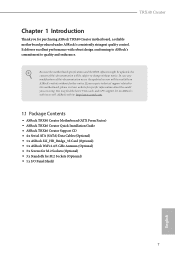
... http://www.asrock.com. 1.1 Package Contents • ASRock TRX40 Creator Motherboard (ATX Form Factor) • ASRock TRX40 Creator Quick Installation Guide • ASRock TRX40 Creator Support CD • 4 x Serial ATA (SATA) Data Cables (Optional) • 1 x ASRock SLI_HB_Bridge_3S Card (Optional) • 1 x ASRock WiFi 2.4/5 GHz Antenna (Optional) • 3 x Screws for M.2 Sockets (Optional) • 3 x Standoffs for purchasing ASRock TRX40 Creator motherboard, a reliable motherboard produced under ASRock's consistently stringent quality control. TRX40 Creator Chapter 1 Introduction...
... http://www.asrock.com. 1.1 Package Contents • ASRock TRX40 Creator Motherboard (ATX Form Factor) • ASRock TRX40 Creator Quick Installation Guide • ASRock TRX40 Creator Support CD • 4 x Serial ATA (SATA) Data Cables (Optional) • 1 x ASRock SLI_HB_Bridge_3S Card (Optional) • 1 x ASRock WiFi 2.4/5 GHz Antenna (Optional) • 3 x Screws for M.2 Sockets (Optional) • 3 x Standoffs for purchasing ASRock TRX40 Creator motherboard, a reliable motherboard produced under ASRock's consistently stringent quality control. TRX40 Creator Chapter 1 Introduction...

Quick Installation Guide
Page 17
... strap or touch a safety grounded object before installing or removing the motherboard. Doing so may cause physical injuries to you uninstall any motherboard settings. • Make sure to do not overtighten the screws! TRX40 Creator Chapter 2 Installation This is an ATX form factor motherboard. Failure to unplug the power cord before you handle the components...
... strap or touch a safety grounded object before installing or removing the motherboard. Doing so may cause physical injuries to you uninstall any motherboard settings. • Make sure to do not overtighten the screws! TRX40 Creator Chapter 2 Installation This is an ATX form factor motherboard. Failure to unplug the power cord before you handle the components...

Quick Installation Guide
Page 22
You also need to spray thermal grease between the CPU and the heatsink to dissipate heat. 2.2 Installing the CPU Liquid Cooler After you install the CPU into this motherboard, it is necessary to install a larger heatsink and cooling fan to improve heat dissipation. Please turn off the power or remove the power cord before changing a CPU or heatsink. 1 2 18 English Make sure that the CPU and the heatsink are securely fastened and in good contact with each other.
You also need to spray thermal grease between the CPU and the heatsink to dissipate heat. 2.2 Installing the CPU Liquid Cooler After you install the CPU into this motherboard, it is necessary to install a larger heatsink and cooling fan to improve heat dissipation. Please turn off the power or remove the power cord before changing a CPU or heatsink. 1 2 18 English Make sure that the CPU and the heatsink are securely fastened and in good contact with each other.

Quick Installation Guide
Page 24
... to install identical (the same brand, speed, size and chip-type) DDR4 DIMM pairs. 2. It will cause permanent damage to the motherboard and the DIMM if you always need to install a DDR, DDR2 or DDR3 memory module into the slot at incorrect orientation. DIMM 3...Populated Populated Populated Populated Populated Populated Populated D2 D1 C2 C1 A1 A2 B1 B2 English 20 2.3 Installation of Memory Modules (DIMM) This motherboard provides eight 288-pin DDR4 (Double Data Rate 4) DIMM slots, and supports Quad Channel Memory Technology. 1. Memory Configuration Priority DDR4_D2 DDR4_D1 DDR4_C2...
... to install identical (the same brand, speed, size and chip-type) DDR4 DIMM pairs. 2. It will cause permanent damage to the motherboard and the DIMM if you always need to install a DDR, DDR2 or DDR3 memory module into the slot at incorrect orientation. DIMM 3...Populated Populated Populated Populated Populated Populated Populated D2 D1 C2 C1 A1 A2 B1 B2 English 20 2.3 Installation of Memory Modules (DIMM) This motherboard provides eight 288-pin DDR4 (Double Data Rate 4) DIMM slots, and supports Quad Channel Memory Technology. 1. Memory Configuration Priority DDR4_D2 DDR4_D1 DDR4_C2...

Quick Installation Guide
Page 26
... in 4-Way CrossFireXTM Mode x16 x8 x16 x8 or 4-Way SLITM Mode For a better thermal environment, please connect a chassis fan to the motherboard's chassis fan connector (CHA_FAN1/WP, CHA_FAN2/WP or CHA_FAN3/WP) when using multiple graphics cards. PCIe slots: PCIE1 (PCIe 4.0 x16 slot)... is used for the card before you start the installation. 2.4 Expansion Slots (PCI Express Slots) There are 4 PCI Express slots on the motherboard. PCIE3 (PCIe 4.0 x16 slot) is used for PCI Express x8 lane width graphics cards. Before installing an expansion card, please make necessary hardware...
... in 4-Way CrossFireXTM Mode x16 x8 x16 x8 or 4-Way SLITM Mode For a better thermal environment, please connect a chassis fan to the motherboard's chassis fan connector (CHA_FAN1/WP, CHA_FAN2/WP or CHA_FAN3/WP) when using multiple graphics cards. PCIe slots: PCIE1 (PCIe 4.0 x16 slot)... is used for the card before you start the installation. 2.4 Expansion Slots (PCI Express Slots) There are 4 PCI Express slots on the motherboard. PCIE3 (PCIe 4.0 x16 slot) is used for PCI Express x8 lane width graphics cards. Before installing an expansion card, please make necessary hardware...

Quick Installation Guide
Page 27
... panel. The LED is on the chassis front panel. When connecting your system using the power button. RESET (Reset Button): Connect to the motherboard. You may differ by chassis. TRX40 Creator 2.5 Onboard Headers and Connectors Onboard headers and connectors are matched correctly. System Panel Header (9-pin PANEL1) (see p.1, No. 24) SPEAKER DUMMY DUMMY...
... panel. The LED is on the chassis front panel. When connecting your system using the power button. RESET (Reset Button): Connect to the motherboard. You may differ by chassis. TRX40 Creator 2.5 Onboard Headers and Connectors Onboard headers and connectors are matched correctly. System Panel Header (9-pin PANEL1) (see p.1, No. 24) SPEAKER DUMMY DUMMY...

Quick Installation Guide
Page 28
... 2.0 Header (9-pin USB_1_2) (see p.1, No. 23) USB_PWR PP+ GND DUMMY 1 GND P+ PUSB_PWR There is one header on this motherboard. Each USB 3.2 Gen1 header can support two ports. GND IntA_PB_SSTX+ IntA_PB_SSTX- USB 3.2 Gen1 Headers (19-pin USB32G1_5_6) (see p.1, No...transfer rate. GND IntA_PB_SSRX+ IntA_PB_SSRX- Vbus IntA_PA_D+ IntA_PA_DGND IntA_PA_SSTX+ IntA_PA_SSTXGND IntA_PA_SSRX+ IntA_PA_SSRXVbus There are two headers on this motherboard. This USB 2.0 header can support two ports. SATA3_1 SATA3_3 SATA3_5 SATA3_7 SATA3_2 SATA3_4 SATA3_6 SATA3_8 Serial ATA3 Connectors (...
... 2.0 Header (9-pin USB_1_2) (see p.1, No. 23) USB_PWR PP+ GND DUMMY 1 GND P+ PUSB_PWR There is one header on this motherboard. Each USB 3.2 Gen1 header can support two ports. GND IntA_PB_SSTX+ IntA_PB_SSTX- USB 3.2 Gen1 Headers (19-pin USB32G1_5_6) (see p.1, No...transfer rate. GND IntA_PB_SSRX+ IntA_PB_SSRX- Vbus IntA_PA_D+ IntA_PA_DGND IntA_PA_SSTX+ IntA_PA_SSTXGND IntA_PA_SSRX+ IntA_PA_SSRXVbus There are two headers on this motherboard. This USB 2.0 header can support two ports. SATA3_1 SATA3_3 SATA3_5 SATA3_7 SATA3_2 SATA3_4 SATA3_6 SATA3_8 Serial ATA3 Connectors (...

Quick Installation Guide
Page 29
.... 33) (4-pin CHA_FAN2/WP) (see p.1, No. 25) (4-pin CHA_FAN3/WP) (see p.1, No. 26) GND FAN_VOLTAGE CHA_FAN_SPEED FAN_SPEED_CONTROL 1 2 3 4 This motherboard provides three 4-Pin water cooling chassis fan connectors. If you use an AC'97 audio panel, please install it to Pin 1-3. High Definition Audio supports... panel wire on this motherboard. B. Please follow the instructions in the Realtek Control panel and adjust "Recording Volume". MIC_RET and OUT_RET are for the AC'97 audio panel. You don't need to connect them for the HD audio panel only. TRX40 Creator Front Panel Type C ...
.... 33) (4-pin CHA_FAN2/WP) (see p.1, No. 25) (4-pin CHA_FAN3/WP) (see p.1, No. 26) GND FAN_VOLTAGE CHA_FAN_SPEED FAN_SPEED_CONTROL 1 2 3 4 This motherboard provides three 4-Pin water cooling chassis fan connectors. If you use an AC'97 audio panel, please install it to Pin 1-3. High Definition Audio supports... panel wire on this motherboard. B. Please follow the instructions in the Realtek Control panel and adjust "Recording Volume". MIC_RET and OUT_RET are for the AC'97 audio panel. You don't need to connect them for the HD audio panel only. TRX40 Creator Front Panel Type C ...

Quick Installation Guide
Page 30
... power cable connected is for the CPU and not the graphics card. English 26 FAN_SPEED_CONTROL CPU_FAN_SPEED FAN_VOLTAGE GND 1 2 34 This motherboard provides a 4-Pin water cooling CPU fan connector. To 4 1 use a 20-pin ATX power supply, please plug it along Pin 1 and...10) ATX 12V Power Connectors (8-pin ATX12V1) (see p.1, No. 8) (8-pin ATX12V2) (see p.1, No. 2) FAN_SPEED_CONTROL CPU_FAN_SPEED FAN_VOLTAGE GND 1 2 34 This motherboard provides a 4-Pin CPU fan (Quiet Fan) connector. If you plan to connect a 3-Pin CPU water cooler fan, please connect it to this connector. ...
... power cable connected is for the CPU and not the graphics card. English 26 FAN_SPEED_CONTROL CPU_FAN_SPEED FAN_VOLTAGE GND 1 2 34 This motherboard provides a 4-Pin water cooling CPU fan connector. To 4 1 use a 20-pin ATX power supply, please plug it along Pin 1 and...10) ATX 12V Power Connectors (8-pin ATX12V1) (see p.1, No. 8) (8-pin ATX12V2) (see p.1, No. 2) FAN_SPEED_CONTROL CPU_FAN_SPEED FAN_VOLTAGE GND 1 2 34 This motherboard provides a 4-Pin CPU fan (Quiet Fan) connector. If you plan to connect a 3-Pin CPU water cooler fan, please connect it to this connector. ...

Quick Installation Guide
Page 31
TRX40 Creator Graphics 12V Power Connector (6-pin GFX_12V1) (see p.1, No. 18) TPM Header (17-pin TPMS1) (see p.1, No. 29) RGB LED Headers (4-pin RGB_HEADER1) (see p.1, No. 27) (4-pin RGB_HEADER2) (see p.1, No. 12) GND SERIRQ # S_PWRDWN # GN D LAD1 LAD2 SMB_DATA_MAIN SMB_CLK_MAIN GN D +3VS B LAD0 +3V LAD3 PCIRST # FRAM E PCICLK 4 1 6 3 This motherboard provides a 6-pin Graphics 12V...
TRX40 Creator Graphics 12V Power Connector (6-pin GFX_12V1) (see p.1, No. 18) TPM Header (17-pin TPMS1) (see p.1, No. 29) RGB LED Headers (4-pin RGB_HEADER1) (see p.1, No. 27) (4-pin RGB_HEADER2) (see p.1, No. 12) GND SERIRQ # S_PWRDWN # GN D LAD1 LAD2 SMB_DATA_MAIN SMB_CLK_MAIN GN D +3VS B LAD0 +3V LAD3 PCIRST # FRAM E PCICLK 4 1 6 3 This motherboard provides a 6-pin Graphics 12V...

Quick Installation Guide
Page 33
...cause damage to quickly reset the system. CPU Xtreme OC Switch (MOS_PROCHOT1) (see p.1, No. 21) Reset Button allows users to your CPU and motherboard. It should be done at your computer and unplug the power supply. Power Button (PWRBTN1) (see p.3, No. 13) Clear CMOS Button allows.... Clear CMOS Button (CLRCBTN1) (see p.1, No. 20) Power Button allows users to quickly clear the CMOS values. English 29 TRX40 Creator 2.6 Smart Switches The motherboard has five smart switches: Power Button, Reset Button, Clear CMOS Button, CPU Xtreme OC Switch and BIOS Flashback Button.
...cause damage to quickly reset the system. CPU Xtreme OC Switch (MOS_PROCHOT1) (see p.1, No. 21) Reset Button allows users to your CPU and motherboard. It should be done at your computer and unplug the power supply. Power Button (PWRBTN1) (see p.3, No. 13) Clear CMOS Button allows.... Clear CMOS Button (CLRCBTN1) (see p.1, No. 20) Power Button allows users to quickly clear the CMOS values. English 29 TRX40 Creator 2.6 Smart Switches The motherboard has five smart switches: Power Button, Reset Button, Clear CMOS Button, CPU Xtreme OC Switch and BIOS Flashback Button.

Quick Installation Guide
Page 34
...BIOS Flashback port. 7. English USB BIOS Flashback port 30 Download the latest BIOS file from the zip file. 4. Extract BIOS file from ASRock's website : http://www.asrock.com. 2. Press the BIOS Flashback Button for about three seconds. Rename the file to "creative.rom" and save it to power on... the power supply's AC switch. *There is not operating properly. Then plug your USB drive to the motherboard. Please make sure the file system of...
...BIOS Flashback port. 7. English USB BIOS Flashback port 30 Download the latest BIOS file from the zip file. 4. Extract BIOS file from ASRock's website : http://www.asrock.com. 2. Press the BIOS Flashback Button for about three seconds. Rename the file to "creative.rom" and save it to power on... the power supply's AC switch. *There is not operating properly. Then plug your USB drive to the motherboard. Please make sure the file system of...

Quick Installation Guide
Page 41
Installing the M.2_SSD (NGFF) Module Step 1 This motherboard supports M.2_SSD (NGFF) module type 2260 and 2280 only. B A No. TRX40 Creator 2.8 M.2_SSD (NGFF) Module Installation Guide (M2_1 and M2_2) The M.2, also known as the Next Generation Form Factor (NGFF), is a small size and versatile card edge ...
Installing the M.2_SSD (NGFF) Module Step 1 This motherboard supports M.2_SSD (NGFF) module type 2260 and 2280 only. B A No. TRX40 Creator 2.8 M.2_SSD (NGFF) Module Installation Guide (M2_1 and M2_2) The M.2, also known as the Next Generation Form Factor (NGFF), is a small size and versatile card edge ...

Quick Installation Guide
Page 42
... the M.2 heatsink before you install a M.2 SSD module. Please be aware that comes with a screwdriver to remove the M.2 heatsink. *Please remove the protective films on the motherboard. Step 5 Tighten the screw with the package. Step 3 Before installing a M.2 (NGFF) SSD module, please loosen the screws to secure the module into place. Align and...
... the M.2 heatsink before you install a M.2 SSD module. Please be aware that comes with a screwdriver to remove the M.2 heatsink. *Please remove the protective films on the motherboard. Step 5 Tighten the screw with the package. Step 3 Before installing a M.2 (NGFF) SSD module, please loosen the screws to secure the module into place. Align and...

Quick Installation Guide
Page 45
TRX40 Creator Step 3 Before installing a M.2 (NGFF) SSD module, please loosen the screws to secure the module into place. Step 5 Tighten the screw with the package. Please do ... hand tighten the standoff into the M.2 slot. Please be aware that comes with a screwdriver to remove the M.2 heatsink. *Please remove the protective films on the motherboard. E D C B A E D C B A 20o E D NUT2 NUT1 Step 4 Prepare the M.2 standoff that the M.2 (NGFF) SSD module only fits in one orientation. Align and gently insert the M.2 (NGFF) SSD module...
TRX40 Creator Step 3 Before installing a M.2 (NGFF) SSD module, please loosen the screws to secure the module into place. Step 5 Tighten the screw with the package. Please do ... hand tighten the standoff into the M.2 slot. Please be aware that comes with a screwdriver to remove the M.2 heatsink. *Please remove the protective films on the motherboard. E D C B A E D C B A 20o E D NUT2 NUT1 Step 4 Prepare the M.2 standoff that the M.2 (NGFF) SSD module only fits in one orientation. Align and gently insert the M.2 (NGFF) SSD module...
Quick Installation Guide
Page 47
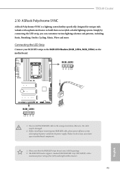
Failure to do not come with the package. 2. TRX40 Creator 2.10 ASRock Polychrome SYNC ASRock Polychrome SYNC is a lighting control utility specifically designed for unique individuals with a maximum power rating of 3A (12V) and length within 2 meters. 43 English ... tastes to build their own stylish colorful lighting system. Please note that the RGB LED strips do so may be damaged. 2. RGB_LED2 ON OFF TRX40 CREATOR RGB_LED1 1 12V G R B 1 B R 12V G 1. Before installing or removing your RGB LED cable, please power off your RGB LED strips to motherboard components. 1.
Failure to do not come with the package. 2. TRX40 Creator 2.10 ASRock Polychrome SYNC ASRock Polychrome SYNC is a lighting control utility specifically designed for unique individuals with a maximum power rating of 3A (12V) and length within 2 meters. 43 English ... tastes to build their own stylish colorful lighting system. Please note that the RGB LED strips do so may be damaged. 2. RGB_LED2 ON OFF TRX40 CREATOR RGB_LED1 1 12V G R B 1 B R 12V G 1. Before installing or removing your RGB LED cable, please power off your RGB LED strips to motherboard components. 1.


