User Manual
Page 3
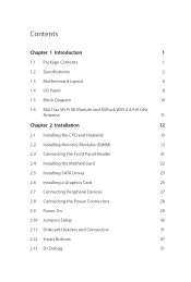
... Specifications 2 1.3 Motherboard Layout 6 1.4 I/O Panel 8 1.5 Block Diagram 10 1.6 802.11ax Wi-Fi 6E Module and ASRock WiFi 2.4/5/6 GHz Antenna 11 Chapter 2 Installation 12 2.1 Installing the CPU and Heatsink 13 2.2 Installing Memory Modules (DIMM) 19 2.3 Connecting the Front Panel Header 21 2.4 Installing the Motherboard 22 2.5 Installing SATA Drives 23 2.6 Installing a Graphics Card 25 2.7 Connecting Peripheral Devices 27 2.8 Connecting the Power Connectors 28 2.9 Power On 29 2.10 Jumpers Setup 30 2.11 Onboard Headers and Connectors 31 2.12 Smart Buttons...
... Specifications 2 1.3 Motherboard Layout 6 1.4 I/O Panel 8 1.5 Block Diagram 10 1.6 802.11ax Wi-Fi 6E Module and ASRock WiFi 2.4/5/6 GHz Antenna 11 Chapter 2 Installation 12 2.1 Installing the CPU and Heatsink 13 2.2 Installing Memory Modules (DIMM) 19 2.3 Connecting the Front Panel Header 21 2.4 Installing the Motherboard 22 2.5 Installing SATA Drives 23 2.6 Installing a Graphics Card 25 2.7 Connecting Peripheral Devices 27 2.8 Connecting the Power Connectors 28 2.9 Power On 29 2.10 Jumpers Setup 30 2.11 Onboard Headers and Connectors 31 2.12 Smart Buttons...
User Manual
Page 7
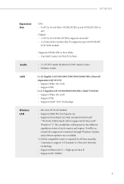
...; Windows® 11. W790 WS Expansion Slot CPU: • 4 x PCIe 5.0 x16 Slots (PCIE1/PCIE3 at x8)* Chipset: • 1 x PCIe 4.0 x16 Slot (PCIE4), supports x4 mode* • 1 x Vertical M.2 Socket (Key E), supports type 2230 WiFi/BT PCIe WiFi module * Supports NVMe SSD as boot disks • 15μ Gold Contact in VGA PCIe Slots Audio • 7.1 CH HD Audio (Realtek ALC897 Audio Codec) • Nahimic Audio LAN 2 x 10 Gigabit LAN 100/1000/2500/5000/10000 Mb/s (Marvell (Aquantia) AQC113CS) • Support Wake-On-LAN...
...; Windows® 11. W790 WS Expansion Slot CPU: • 4 x PCIe 5.0 x16 Slots (PCIE1/PCIE3 at x8)* Chipset: • 1 x PCIe 4.0 x16 Slot (PCIE4), supports x4 mode* • 1 x Vertical M.2 Socket (Key E), supports type 2230 WiFi/BT PCIe WiFi module * Supports NVMe SSD as boot disks • 15μ Gold Contact in VGA PCIe Slots Audio • 7.1 CH HD Audio (Realtek ALC897 Audio Codec) • Nahimic Audio LAN 2 x 10 Gigabit LAN 100/1000/2500/5000/10000 Mb/s (Marvell (Aquantia) AQC113CS) • Support Wake-On-LAN...
User Manual
Page 8
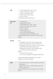
... M2_3, Key M), support type 2260/2280 PCIe Gen5x4 (128 Gb/s) mode* • 1 x Blazing M.2 Socket (M2_4, Key M), supports type 2260/2280 PCIe Gen5x4 (128 Gb/s) mode* Chipset: • 8 x SATA3 6.0 Gb/s Connectors • 1 x U.2 Connector, supports PCIe Gen4x4 (64 Gb/s) mode * Supports Intel® Volume Management Device (VMD) * Supports NVMe SSD as boot disks RAID • Supports RAID 0, RAID 1, RAID 5 and RAID 10 for SATA storage devices • Supports RAID 0, RAID 1, RAID 5 and RAID 10 for M.2 NVMe storage devices* * Requires additional M.2 NVMe expansion cards to support RAID 10 4
... M2_3, Key M), support type 2260/2280 PCIe Gen5x4 (128 Gb/s) mode* • 1 x Blazing M.2 Socket (M2_4, Key M), supports type 2260/2280 PCIe Gen5x4 (128 Gb/s) mode* Chipset: • 8 x SATA3 6.0 Gb/s Connectors • 1 x U.2 Connector, supports PCIe Gen4x4 (64 Gb/s) mode * Supports Intel® Volume Management Device (VMD) * Supports NVMe SSD as boot disks RAID • Supports RAID 0, RAID 1, RAID 5 and RAID 10 for SATA storage devices • Supports RAID 0, RAID 1, RAID 5 and RAID 10 for M.2 NVMe storage devices* * Requires additional M.2 NVMe expansion cards to support RAID 10 4
User Manual
Page 9
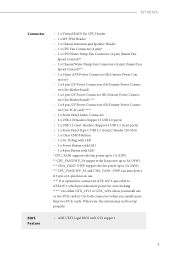
... use. **** It is optional to connect an ATX 12V 6-pin cable to 3A (36W). *** CHA_FAN1~3/WP support the fan power up properly. tor) (for Motherboard) • 1 x 6 pin 12V Power Connector (Hi-Density Power Connec- BIOS Feature • AMI UEFI Legal BIOS with LED * CPU_FAN1 supports the fan power up to 1A (12W). ** CPU_FAN2/WP_3A supports the fan power up to ATX12V3, which provides more than two PCIe cards. nector) • 2 x 8 pin 12V Power Connectors (Hi-Density Power Connec- W790 WS Connector • 1 x Virtual RAID On CPU Header...
... use. **** It is optional to connect an ATX 12V 6-pin cable to 3A (36W). *** CHA_FAN1~3/WP support the fan power up properly. tor) (for Motherboard) • 1 x 6 pin 12V Power Connector (Hi-Density Power Connec- BIOS Feature • AMI UEFI Legal BIOS with LED * CPU_FAN1 supports the fan power up to 1A (12W). ** CPU_FAN2/WP_3A supports the fan power up to ATX12V3, which provides more than two PCIe cards. nector) • 2 x 8 pin 12V Power Connectors (Hi-Density Power Connec- W790 WS Connector • 1 x Virtual RAID On CPU Header...
User Manual
Page 11
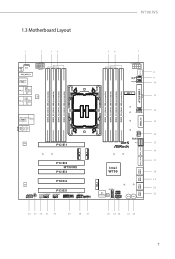
1.3 Motherboard Layout W790 WS 1 2 34 1 BIOS VROC1 _FB1 M2_WIFI_2 USB 3.2 Gen1 T: USB32_1 B: USB32_2 ATX12V1 USB 3.2 Gen1 USB32_5 TB_1 TB_2 Top: 10GLAN (Marvell (Aquantia) AQC113CS ) Top: 10GLAN (Marvell (Aquantia) AQC113CS ) LAN USB 3.2 Gen1 USB32_6 USB 3.2 Gen2 Top: T: USB3_5 2.5GLAN (Intel I225LM) B: USB3_6 56 7 ATX12V2 CPU_FAN2 /WP_3A CPU_FAN1 M2_1 ATX12V3 8 9 10 11 ATXPWR1 CHA_FAN1/WP 12 13 DDR5_B2 (64 bit, 288-pin module) DDR5_B1 (64...
1.3 Motherboard Layout W790 WS 1 2 34 1 BIOS VROC1 _FB1 M2_WIFI_2 USB 3.2 Gen1 T: USB32_1 B: USB32_2 ATX12V1 USB 3.2 Gen1 USB32_5 TB_1 TB_2 Top: 10GLAN (Marvell (Aquantia) AQC113CS ) Top: 10GLAN (Marvell (Aquantia) AQC113CS ) LAN USB 3.2 Gen1 USB32_6 USB 3.2 Gen2 Top: T: USB3_5 2.5GLAN (Intel I225LM) B: USB3_6 56 7 ATX12V2 CPU_FAN2 /WP_3A CPU_FAN1 M2_1 ATX12V3 8 9 10 11 ATXPWR1 CHA_FAN1/WP 12 13 DDR5_B2 (64 bit, 288-pin module) DDR5_B1 (64...
User Manual
Page 31
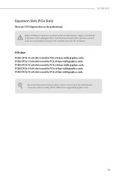
.... Please read the documentation of the expansion card and make sure that the power supply is switched off or the power cord is used for PCIe x16 lane width graphics cards. Before installing an expansion card, please make necessary hardware settings for PCIe x8 lane width graphics cards. For a better thermal environment, please connect a chassis fan to the motherboard's chassis fan connector (CHA_FAN1~3/WP) when using multiple graphics cards. 27 W790 WS Expansion Slots (PCIe Slots) There are 5 PCI Express slots on the motherboard.
.... Please read the documentation of the expansion card and make sure that the power supply is switched off or the power cord is used for PCIe x16 lane width graphics cards. Before installing an expansion card, please make necessary hardware settings for PCIe x8 lane width graphics cards. For a better thermal environment, please connect a chassis fan to the motherboard's chassis fan connector (CHA_FAN1~3/WP) when using multiple graphics cards. 27 W790 WS Expansion Slots (PCIe Slots) There are 5 PCI Express slots on the motherboard.
User Manual
Page 55
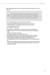
... unpredictable failure may occur. Plug the 24 pin power connector to disable fTPM before updating the BIOS. Then the LED starts to the USB BIOS Flashback port. **If the LED does not light up at all then please disconnect power from the system and remove/ disconnect the CMOS battery from the motherboard for about three seconds. Please make sure the file system of X: USB flash drive. 5. Download the latest BIOS file from the zip file. 4. If the recovery key is...
... unpredictable failure may occur. Plug the 24 pin power connector to disable fTPM before updating the BIOS. Then the LED starts to the USB BIOS Flashback port. **If the LED does not light up at all then please disconnect power from the system and remove/ disconnect the CMOS battery from the motherboard for about three seconds. Please make sure the file system of X: USB flash drive. 5. Download the latest BIOS file from the zip file. 4. If the recovery key is...
User Manual
Page 66
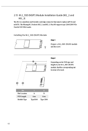
B A No. Nut Location PCB Length Module Type 1 A 6cm Type2260 2 B 8cm Type 2280 62 Installing the M.2_SSD (NGFF) Module Step 1 Prepare a M.2_SSD (NGFF) module and the screw. Step 2 2 Depending on the PCB type and 1 length of your M.2_SSD (NGFF) module, find the corresponding nut location to replace mPCIe and mSATA. 2.15 M.2_SSD (NGFF) Module Installation Guide (M2_2 and M2_3) The M.2 is a small size and versatile card edge connector that aims to be used. The Blazing M.2 Sockets (M2_2 and M2_3, Key M) support type 2260/2280 PCIe Gen5x4 (128 Gb/s) mode.
B A No. Nut Location PCB Length Module Type 1 A 6cm Type2260 2 B 8cm Type 2280 62 Installing the M.2_SSD (NGFF) Module Step 1 Prepare a M.2_SSD (NGFF) module and the screw. Step 2 2 Depending on the PCB type and 1 length of your M.2_SSD (NGFF) module, find the corresponding nut location to replace mPCIe and mSATA. 2.15 M.2_SSD (NGFF) Module Installation Guide (M2_2 and M2_3) The M.2 is a small size and versatile card edge connector that aims to be used. The Blazing M.2 Sockets (M2_2 and M2_3, Key M) support type 2260/2280 PCIe Gen5x4 (128 Gb/s) mode.

User Manual
Page 69
The Blazing M.2 Socket (M2_4, Key M) supports type 2260/2280 PCIe Gen5x4 (128 Gb/s) mode. Nut Location PCB Length Module Type 1 A 6cm Type2260 2 B 8cm Type 2280 65 W790 WS 2.16 M.2_SSD (NGFF) Module Installation Guide (M2_4) The M.2, also known as the Next Generation Form Factor (NGFF), is a small size and versatile card edge connector that aims to be used. Installing the M.2_SSD (NGFF) Module Step 1 Prepare a M.2_SSD (NGFF) module and...
The Blazing M.2 Socket (M2_4, Key M) supports type 2260/2280 PCIe Gen5x4 (128 Gb/s) mode. Nut Location PCB Length Module Type 1 A 6cm Type2260 2 B 8cm Type 2280 65 W790 WS 2.16 M.2_SSD (NGFF) Module Installation Guide (M2_4) The M.2, also known as the Next Generation Form Factor (NGFF), is a small size and versatile card edge connector that aims to be used. Installing the M.2_SSD (NGFF) Module Step 1 Prepare a M.2_SSD (NGFF) module and...

Software/BIOS Setup Guide
Page 3
... (ADI) 2 2.1.1 Installing Drivers for the First Time 2 2.1.2 Updating Drivers 6 2.2 ASRock Live Update & APP Shop 7 2.2.1 Installing ASRock Live Update & APP Shop 7 2.2.2 UI Overview 8 2.2.3 Apps 9 2.2.4 BIOS & Drivers 12 2.2.5 Setting 13 2.3 ASRock Motherboard Utility (A-Tuning) 14 2.3.1 Installing ASRock Motherboard Utility (A-Tuning) 14 2.3.2 Using ASRock Motherboard Utility (A-Tuning) 14 2.4 Nahimic Audio 17 Chapter 3 UEFI SETUP UTILITY 19 3.1 Introduction 19 3.1.1 Entering BIOS Setup 19 3.1.2 UEFI Menu Bar 20 3.1.3 Navigation Keys 21 3.2 Main Screen 22...
... (ADI) 2 2.1.1 Installing Drivers for the First Time 2 2.1.2 Updating Drivers 6 2.2 ASRock Live Update & APP Shop 7 2.2.1 Installing ASRock Live Update & APP Shop 7 2.2.2 UI Overview 8 2.2.3 Apps 9 2.2.4 BIOS & Drivers 12 2.2.5 Setting 13 2.3 ASRock Motherboard Utility (A-Tuning) 14 2.3.1 Installing ASRock Motherboard Utility (A-Tuning) 14 2.3.2 Using ASRock Motherboard Utility (A-Tuning) 14 2.4 Nahimic Audio 17 Chapter 3 UEFI SETUP UTILITY 19 3.1 Introduction 19 3.1.1 Entering BIOS Setup 19 3.1.2 UEFI Menu Bar 20 3.1.3 Navigation Keys 21 3.2 Main Screen 22...
Software/BIOS Setup Guide
Page 5
... configuration guide of the software and utilities. Software Setup Guide • Auto Driver Installer (ADI) • ASRock Live Update & APP Shop • ASRock Motherboard Utility (A-Tuning) • Nahimic Audio BIOS Setup Guide • UEFI Setup Utility Because the motherboard specifications and the software might be updated, the content of this documentation will be subject to change without further notice. Chapter 2 contains the operation guide of the BIOS setup. In case any modifications of the setup guide. If you require technical support related to the motherboard...
... configuration guide of the software and utilities. Software Setup Guide • Auto Driver Installer (ADI) • ASRock Live Update & APP Shop • ASRock Motherboard Utility (A-Tuning) • Nahimic Audio BIOS Setup Guide • UEFI Setup Utility Because the motherboard specifications and the software might be updated, the content of this documentation will be subject to change without further notice. Chapter 2 contains the operation guide of the BIOS setup. In case any modifications of the setup guide. If you require technical support related to the motherboard...

Software/BIOS Setup Guide
Page 7
... installation. 1. The Auto Driver Installer will automatically pop up . 3. The item is set to change the setting in the BIOS is enabled by default; therefore, for using the Auto Driver Installer. An available Internet connection is a prerequisite for the first-time users, there is no need to [Enabled]. Now connect your desktop and then the Auto Driver Installer appears. 3 If you will see the Auto Driver Installer icon on your computer to install drivers only when the "Auto Driver Installer...
... installation. 1. The Auto Driver Installer will automatically pop up . 3. The item is set to change the setting in the BIOS is enabled by default; therefore, for using the Auto Driver Installer. An available Internet connection is a prerequisite for the first-time users, there is no need to [Enabled]. Now connect your desktop and then the Auto Driver Installer appears. 3 If you will see the Auto Driver Installer icon on your computer to install drivers only when the "Auto Driver Installer...

Software/BIOS Setup Guide
Page 9
... 6 Once all drivers are successfully installed, a message pops up saying, "During installation, your computer. For further drivers and utilities, please visit ASRock's website." Intel W790 Series Step 5 A messages pops up saying, "Installation has been successfully completed! Click "Ok" to exit. If you would like to run the application again, please go to the "Tool" menu in the BIOS setting, and set the "Auto Driver Installer" item...
... 6 Once all drivers are successfully installed, a message pops up saying, "During installation, your computer. For further drivers and utilities, please visit ASRock's website." Intel W790 Series Step 5 A messages pops up saying, "Installation has been successfully completed! Click "Ok" to exit. If you would like to run the application again, please go to the "Tool" menu in the BIOS setting, and set the "Auto Driver Installer" item...

Software/BIOS Setup Guide
Page 23
... the UEFI default configurations or change the setting, try to clear the CMOS values and reset the board to configure all the supported system. This setup guide explains how to use the UEFI SETUP UTILITY to default values. UEFI Settings and options may cause system instability, mulfunction or boot failure. The battery on the motherboard supplies the power needed to different BIOS release versions or CPU installed. We strongly recommend that inadequate BIOS settings may vary owing to the CMOS when the system power is a BIOS utility...
... the UEFI default configurations or change the setting, try to clear the CMOS values and reset the board to configure all the supported system. This setup guide explains how to use the UEFI SETUP UTILITY to default values. UEFI Settings and options may cause system instability, mulfunction or boot failure. The battery on the motherboard supplies the power needed to different BIOS release versions or CPU installed. We strongly recommend that inadequate BIOS settings may vary owing to the CMOS when the system power is a BIOS utility...
Software/BIOS Setup Guide
Page 51
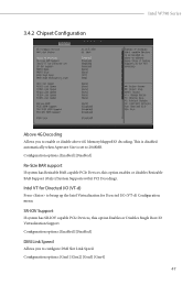
... has SR-IOV capable PCIe Devices, this option enables or disables Resizable BAR Support (Only if System Supports 64 bit PCI Decoding). Configuration options: [Enabled] [Disabled] Re-Size BAR support If system has Resizable BAR capable PCIe Devices, this option Enables or Disables Single Root IO Virtualization Support. Configuration options: [Gen1] [Gen2] [Gen3] [Gen4] 47 3.4.2 Chipset Configuration Intel W790 Series Above 4G Decoding Allows you to configure DMI Slot Link Speed. Intel VT for Directed I/O (VT-d) Press to 2048MB. Configuration options: [Enabled] [Disabled] DMI Link...
... has SR-IOV capable PCIe Devices, this option enables or disables Resizable BAR Support (Only if System Supports 64 bit PCI Decoding). Configuration options: [Enabled] [Disabled] Re-Size BAR support If system has Resizable BAR capable PCIe Devices, this option Enables or Disables Single Root IO Virtualization Support. Configuration options: [Gen1] [Gen2] [Gen3] [Gen4] 47 3.4.2 Chipset Configuration Intel W790 Series Above 4G Decoding Allows you to configure DMI Slot Link Speed. Intel VT for Directed I/O (VT-d) Press to 2048MB. Configuration options: [Enabled] [Disabled] DMI Link...
Software/BIOS Setup Guide
Page 53
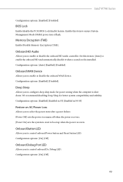
... compatibility and stability. Configuration options: [Enabled] [Enabled in S5] [Enabled in S4-S5] Restore on AC/Power Loss Allows you to boot up when the power recovers. Configuration options: [On] [Off] Onboard Debug Port LED Allows you to control onboard Dr. Debug LED. Configuration options: [On] [Off] 49 Onboard HD Audio Allows you to enable or disable the onboard HD audio controller. Set this item to enable the onboard HD and automatically disable it when a sound card is shut down. Intel W790 Series Configuration options: [Enabled] [Disabled] BIOS Lock Enable/disable...
... compatibility and stability. Configuration options: [Enabled] [Enabled in S5] [Enabled in S4-S5] Restore on AC/Power Loss Allows you to boot up when the power recovers. Configuration options: [On] [Off] Onboard Debug Port LED Allows you to control onboard Dr. Debug LED. Configuration options: [On] [Off] 49 Onboard HD Audio Allows you to enable or disable the onboard HD audio controller. Set this item to enable the onboard HD and automatically disable it when a sound card is shut down. Intel W790 Series Configuration options: [Enabled] [Disabled] BIOS Lock Enable/disable...
Software/BIOS Setup Guide
Page 56
Configuration options: [Enabled] [Disabled] VMD Configuration Press [Enter] to detect and report on various indicators of reliability. Configuration options: [Enabled] [Disabled] Map this Root Port to [Enabled]. Configuration options: [Enabled] [Disabled] Enable VMD Global Mapping Allows you to map or unmap this Root Port under VMD Allows you to enable or disable the VMD Global Mapping. Configuration options: [Enabled] [Disabled] Root Port BDF details Displays the Root Port BDF details. 52 monitoring system for computer hard disk drives to view the followings...
Configuration options: [Enabled] [Disabled] VMD Configuration Press [Enter] to detect and report on various indicators of reliability. Configuration options: [Enabled] [Disabled] Map this Root Port to [Enabled]. Configuration options: [Enabled] [Disabled] Enable VMD Global Mapping Allows you to map or unmap this Root Port under VMD Allows you to enable or disable the VMD Global Mapping. Configuration options: [Enabled] [Disabled] Root Port BDF details Displays the Root Port BDF details. 52 monitoring system for computer hard disk drives to view the followings...
Software/BIOS Setup Guide
Page 74
... load the default Secure Boot keys. Use this item to run in Setup mode. Public Key Certificate: a) EFI_SIGNATURE_LIST b) EFI_CERT_X509 (DER) c) EFI_CERT_RSA2048 (bin) d) EFI_CERT_SHAXXX 70 Clear Secure Boot Keys This item appears only when you to modify Secure Boot Policy variables without full authentication. Key Management This item enables expert users to install factory default Secure Boot keys after the platform reset and while the System is in Secure Boot Mode. Install Default Secure Boot Keys Please install default...
... load the default Secure Boot keys. Use this item to run in Setup mode. Public Key Certificate: a) EFI_SIGNATURE_LIST b) EFI_CERT_X509 (DER) c) EFI_CERT_RSA2048 (bin) d) EFI_CERT_SHAXXX 70 Clear Secure Boot Keys This item appears only when you to modify Secure Boot Policy variables without full authentication. Key Management This item enables expert users to install factory default Secure Boot keys after the platform reset and while the System is in Secure Boot Mode. Install Default Secure Boot Keys Please install default...

Software/BIOS Setup Guide
Page 77
Intel W790 Series Configuration options: [Enabled] [Disabled] Case Open Feature Enable or disable Case Open Feature to detect whether the chassis cover has been removed. 73
Intel W790 Series Configuration options: [Enabled] [Disabled] Case Open Feature Enable or disable Case Open Feature to detect whether the chassis cover has been removed. 73

Intel Rapid Storage Guide
Page 13
... have successfully installed the driver and Windows setup should continue. Select your controller from the list of Windows setup (during operating system setup: 1. Use the up and down arrow keys to Specify Additional Device. 3. Select 4: Exit and press Enter. 11. Use the Floppy Configuration Utility to load support for mass storage device(s). 2. Leave 13 You will then be visible. 6. Select the volume size and press Enter. 8. Press F6 when you to create a floppy disk with...
... have successfully installed the driver and Windows setup should continue. Select your controller from the list of Windows setup (during operating system setup: 1. Use the up and down arrow keys to Specify Additional Device. 3. Select 4: Exit and press Enter. 11. Use the Floppy Configuration Utility to load support for mass storage device(s). 2. Leave 13 You will then be visible. 6. Select the volume size and press Enter. 8. Press F6 when you to create a floppy disk with...


