
User Manual
Page 4
...1.2 Speciications 2 1.3 Motherboard Layout 6 1.4 I/O Panel 8 Chapter 2 Installation 10 2.1 Installing the CPU 11 2.2 Installing the CPU Fan and Heatsink 14 2.3 Installing Memory Modules (DIMM) 15 2.4 Expansion Slots (PCI Express Slots) 17 2.5 Jumpers Setup 18 2.6 Onboard Headers and Connectors 19 2.7 CrossFireXTM and Quad CrossFireXTM Operation Guide 23 2.7.2 Driver Installation and Setup 25 2.8 M.2_SSD (NGFF) Module Installation Guide 26 Chapter 3 Software and Utilities Operation 29 3.1 Installing Drivers 29 3.2 A-Tuning 30 3.3 ASRock Live Update & APP Shop 34...
...1.2 Speciications 2 1.3 Motherboard Layout 6 1.4 I/O Panel 8 Chapter 2 Installation 10 2.1 Installing the CPU 11 2.2 Installing the CPU Fan and Heatsink 14 2.3 Installing Memory Modules (DIMM) 15 2.4 Expansion Slots (PCI Express Slots) 17 2.5 Jumpers Setup 18 2.6 Onboard Headers and Connectors 19 2.7 CrossFireXTM and Quad CrossFireXTM Operation Guide 23 2.7.2 Driver Installation and Setup 25 2.8 M.2_SSD (NGFF) Module Installation Guide 26 Chapter 3 Software and Utilities Operation 29 3.1 Installing Drivers 29 3.2 A-Tuning 30 3.3 ASRock Live Update & APP Shop 34...
User Manual
Page 5
... BIOS & Drivers 38 3.3.4 Setting 39 3.4 Enabling USB Ports for Windows® 7 Installation 40 Chapter 4 UEFI SETUP UTILITY 43 4.1 Introduction 43 4.1.1 UEFI Menu Bar 43 4.1.2 Navigation Keys 44 4.2 Main Screen 45 4.3 OC Tweaker Screen 46 4.4 Advanced Screen 54 4.4.1 CPU Coniguration 55 4.4.2 Chipset Coniguration 57 4.4.3 Storage Coniguration 59 4.4.4 Super IO Coniguration 60 4.4.5 ACPI Coniguration 61 4.4.6 USB Coniguration 63 4.4.7 Trusted Computing 64 4.5 Tools 65 4.6 Hardware Health Event Monitoring Screen 69 4.7 Security Screen 71 4.8 Boot Screen...
... BIOS & Drivers 38 3.3.4 Setting 39 3.4 Enabling USB Ports for Windows® 7 Installation 40 Chapter 4 UEFI SETUP UTILITY 43 4.1 Introduction 43 4.1.1 UEFI Menu Bar 43 4.1.2 Navigation Keys 44 4.2 Main Screen 45 4.3 OC Tweaker Screen 46 4.4 Advanced Screen 54 4.4.1 CPU Coniguration 55 4.4.2 Chipset Coniguration 57 4.4.3 Storage Coniguration 59 4.4.4 Super IO Coniguration 60 4.4.5 ACPI Coniguration 61 4.4.6 USB Coniguration 63 4.4.7 Trusted Computing 64 4.5 Tools 65 4.6 Hardware Health Event Monitoring Screen 69 4.7 Security Screen 71 4.8 Boot Screen...

User Manual
Page 6
... VGA cards and CPU support list on ASRock's website without notice. In case any modiications of the motherboard and step-by-step installation guides. Chapter 3 contains the operation guide of the BIOS setup. ASRock website http://www.asrock.com. 1.1 Package Contents • ASRock Z170M Pro4 Motherboard (Micro ATX Form Factor) • ASRock Z170M Pro4 Quick Installation Guide • ASRock Z170M Pro4 Support CD • 2 x Serial ATA (SATA) Data Cables (Optional) • 1 x I/O Panel Shield • 1 x Screw for purchasing ASRock Z170M Pro4 motherboard, a reliable motherboard...
... VGA cards and CPU support list on ASRock's website without notice. In case any modiications of the motherboard and step-by-step installation guides. Chapter 3 contains the operation guide of the BIOS setup. ASRock website http://www.asrock.com. 1.1 Package Contents • ASRock Z170M Pro4 Motherboard (Micro ATX Form Factor) • ASRock Z170M Pro4 Quick Installation Guide • ASRock Z170M Pro4 Support CD • 2 x Serial ATA (SATA) Data Cables (Optional) • 1 x I/O Panel Shield • 1 x Screw for purchasing ASRock Z170M Pro4 motherboard, a reliable motherboard...

User Manual
Page 8
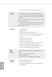
...; Supports DVI-D with max. Z170M Pro4 • Dual graphics output: Support DVI-D and HDMI ports by independent display controllers • Supports HDMI with max. resolution up to use an HD front panel audio module and enable the multi-channel audio feature through the audio driver. • Premium Blu-ray Audio support • Supports Surge Protection (ASRock Full Spike Protection) • ELNA Audio Caps LAN • Gigabit LAN 10/100/1000 Mb/s • Giga PHY Intel® I219V • Supports Wake-On-LAN • Supports...
...; Supports DVI-D with max. Z170M Pro4 • Dual graphics output: Support DVI-D and HDMI ports by independent display controllers • Supports HDMI with max. resolution up to use an HD front panel audio module and enable the multi-channel audio feature through the audio driver. • Premium Blu-ray Audio support • Supports Surge Protection (ASRock Full Spike Protection) • ELNA Audio Caps LAN • Gigabit LAN 10/100/1000 Mb/s • Giga PHY Intel® I219V • Supports Wake-On-LAN • Supports...
User Manual
Page 9
...• DRAM, VCCIO, VCCSA Voltage Multi-adjustment Hardware Monitor • CPU/Chassis temperature sensing • CPU/Chassis Fan Tachometer • CPU/Chassis Quiet Fan (Auto adjust chassis fan speed by CPU temperature) English 4 port • ACPI 1.1 Compliant wake up to Gen3 x4 (32 Gb/s) * Supports ASRock U.2 Kit Connector • 1 x COM Port Header • 1 x TPM Header • 1 x Chassis Intrusion and Speaker Header • 1 x CPU Fan Connector (4-pin) (Smart Fan Speed Control) • 2 x Chassis Fan Connectors (4-pin) (Smart Fan Speed Control) • 1 x 24 pin ATX Power...
...• DRAM, VCCIO, VCCSA Voltage Multi-adjustment Hardware Monitor • CPU/Chassis temperature sensing • CPU/Chassis Fan Tachometer • CPU/Chassis Quiet Fan (Auto adjust chassis fan speed by CPU temperature) English 4 port • ACPI 1.1 Compliant wake up to Gen3 x4 (32 Gb/s) * Supports ASRock U.2 Kit Connector • 1 x COM Port Header • 1 x TPM Header • 1 x Chassis Intrusion and Speaker Header • 1 x CPU Fan Connector (4-pin) (Smart Fan Speed Control) • 2 x Chassis Fan Connectors (4-pin) (Smart Fan Speed Control) • 1 x 24 pin ATX Power...
User Manual
Page 10
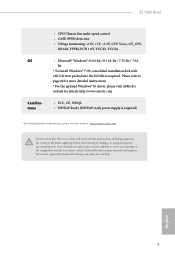
... updated Windows® 10 driver, please visit ASRock's website for possible damage caused by overclocking. Z170M Pro4 OS Certiications • CPU/Chassis Fan multi-speed control • CASE OPEN detection • Voltage monitoring: +12V, +5V, +3.3V, CPU Vcore, GT_CPU, DRAM, VPPM, PCH 1.0V, VCCIO, VCCSA • Microsot® Windows® 10 64-bit / 8.1 64-bit / 7 32-bit / 7 64bit * To install Windows® 7 OS, a modiied installation disk with overclocking, including adjusting the setting in the BIOS, applying Untied Overclocking Technology, or using...
... updated Windows® 10 driver, please visit ASRock's website for possible damage caused by overclocking. Z170M Pro4 OS Certiications • CPU/Chassis Fan multi-speed control • CASE OPEN detection • Voltage monitoring: +12V, +5V, +3.3V, CPU Vcore, GT_CPU, DRAM, VPPM, PCH 1.0V, VCCIO, VCCSA • Microsot® Windows® 10 64-bit / 8.1 64-bit / 7 32-bit / 7 64bit * To install Windows® 7 OS, a modiied installation disk with overclocking, including adjusting the setting in the BIOS, applying Untied Overclocking Technology, or using...
User Manual
Page 12
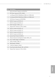
...4 2 x 288-pin DDR4 DIMM Slots (DDR4_A2, DDR4_B2) 5 ATX Power Connector (ATXPWR1) 6 SATA3 Connector (SATA3_0) 7 SATA3 Connector (SATA3_1) 8 USB 3.0 Header (USB3_5_6) 9 Chassis Fan Connector (CHA_FAN2) 10 SATA3 Connector (SATA3_2) 11 SATA3 Connector (SATA3_3) 12 SATA3 Connector (SATA3_5) 13 SATA3 Connector (SATA3_4) 14 System Panel Header (PANEL1) 15 Chassis Intrusion and Speaker Header (SPK_CI1) 16 Clear CMOS Jumper (CLRMOS1) 17 USB 2.0 Header (USB1_2) 18 TPM Header (TPMS1) 19 COM Port Header (COM1) 20 Front Panel Audio Header (HD_AUDIO1) 21 Chassis Fan Connector (CHA_FAN1) Z170M Pro4 English...
...4 2 x 288-pin DDR4 DIMM Slots (DDR4_A2, DDR4_B2) 5 ATX Power Connector (ATXPWR1) 6 SATA3 Connector (SATA3_0) 7 SATA3 Connector (SATA3_1) 8 USB 3.0 Header (USB3_5_6) 9 Chassis Fan Connector (CHA_FAN2) 10 SATA3 Connector (SATA3_2) 11 SATA3 Connector (SATA3_3) 12 SATA3 Connector (SATA3_5) 13 SATA3 Connector (SATA3_4) 14 System Panel Header (PANEL1) 15 Chassis Intrusion and Speaker Header (SPK_CI1) 16 Clear CMOS Jumper (CLRMOS1) 17 USB 2.0 Header (USB1_2) 18 TPM Header (TPMS1) 19 COM Port Header (COM1) 20 Front Panel Audio Header (HD_AUDIO1) 21 Chassis Fan Connector (CHA_FAN1) Z170M Pro4 English...
User Manual
Page 22
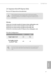
... the power supply is switched of or the power cord is used for the card before you start the installation. PCIE2 (PCIe 3.0 x1 slot) is unplugged. PCIe slots: PCIE1 (PCIe 3.0 x16 slot) is used for PCI Express x1 lane width cards. English 17 PCIE3 (PCIe 3.0 x1 slot) is used for PCI Express x1 lane width cards. PCIe Slot Conigurations Single Graphics Card PCIE1 x16 PCIE4 N/A Two Graphics Cards in CrossFireXTM Mode x16 x4 For a better thermal environment, please connect a chassis fan to the motherboard's chassis fan connector (CHA_FAN1...
... the power supply is switched of or the power cord is used for the card before you start the installation. PCIE2 (PCIe 3.0 x1 slot) is unplugged. PCIe slots: PCIE1 (PCIe 3.0 x16 slot) is used for PCI Express x1 lane width cards. English 17 PCIE3 (PCIe 3.0 x1 slot) is used for PCI Express x1 lane width cards. PCIe Slot Conigurations Single Graphics Card PCIE1 x16 PCIE4 N/A Two Graphics Cards in CrossFireXTM Mode x16 x4 For a better thermal environment, please connect a chassis fan to the motherboard's chassis fan connector (CHA_FAN1...
User Manual
Page 23
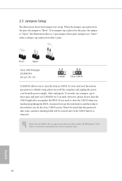
... seconds, use a jumper cap to short pin2 and pin3 on the pins, the jumper is "Open". Clear CMOS Jumper (CLRMOS1) (see p.6, No. 16) Default Clear CMOS CLRMOS1 allows you need to default setup, please turn of previous chassis intrusion status. If you to clear the record of the computer and unplug the power cord from the power supply. However, please do the clear-CMOS action. Please adjust the BIOS option "Clear Status" to clear the...
... seconds, use a jumper cap to short pin2 and pin3 on the pins, the jumper is "Open". Clear CMOS Jumper (CLRMOS1) (see p.6, No. 16) Default Clear CMOS CLRMOS1 allows you need to default setup, please turn of previous chassis intrusion status. If you to clear the record of the computer and unplug the power cord from the power supply. However, please do the clear-CMOS action. Please adjust the BIOS option "Clear Status" to clear the...
User Manual
Page 26
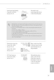
... audio panel only. Please follow the instructions in the Realtek Control panel and adjust "Recording Volume". You don't need to install your system. 2. Chassis Fan Connectors (4-pin CHA_FAN1) (see p.6, No. 21) (4-pin CHA_FAN2) (see p.6, No. 9) CPU Fan Connector (4-pin CPU_FAN1) (see p.6, No. 20) GND PRESENCE# MIC_RET OUT_RET 1 OUT2_L J_SENSE OUT2_R MIC2_R MIC2_L his motherboard provides a 4-Pin CPU fan (Quiet Fan) connector. To activate the front mic, go to the ground pin. Z170M Pro4 Front Panel Audio Header (9-pin...
... audio panel only. Please follow the instructions in the Realtek Control panel and adjust "Recording Volume". You don't need to install your system. 2. Chassis Fan Connectors (4-pin CHA_FAN1) (see p.6, No. 21) (4-pin CHA_FAN2) (see p.6, No. 9) CPU Fan Connector (4-pin CPU_FAN1) (see p.6, No. 20) GND PRESENCE# MIC_RET OUT_RET 1 OUT2_L J_SENSE OUT2_R MIC2_R MIC2_L his motherboard provides a 4-Pin CPU fan (Quiet Fan) connector. To activate the front mic, go to the ground pin. Z170M Pro4 Front Panel Audio Header (9-pin...

User Manual
Page 28
... the graphics cards. (he CrossFire Bridge is recommended to enable CrossFireXTM. Download the drivers from the AMD's website: www.amd.com 3. Please refer to PCIE4 slot. Please refer to three identical PCI Express x16 graphics cards. 1. Make sure that allows you purchase, not bundled with a 16-pipe card, both cards will operate as 12-pipe cards while in CrossFireXTM mode. 5. CrossFire Bridge Step 2 Connect two graphics cards by installing a CrossFire...
... the graphics cards. (he CrossFire Bridge is recommended to enable CrossFireXTM. Download the drivers from the AMD's website: www.amd.com 3. Please refer to PCIE4 slot. Please refer to three identical PCI Express x16 graphics cards. 1. Make sure that allows you purchase, not bundled with a 16-pipe card, both cards will operate as 12-pipe cards while in CrossFireXTM mode. 5. CrossFire Bridge Step 2 Connect two graphics cards by installing a CrossFire...

User Manual
Page 34
... automatically, locate and double click on the support CD driver page. Utilities Menu he Utilities Menu shows the application sotware that enhance the motherboard's features. he drivers compatible to display the menu. herefore, the drivers you install can work properly. Drivers Menu he CD automatically displays the Main Menu if "AUTORUN" is enabled in the Support CD to your system will be auto-detected and listed on the ile "ASRSETUP.EXE" in your CD-ROM drive.
... automatically, locate and double click on the support CD driver page. Utilities Menu he Utilities Menu shows the application sotware that enhance the motherboard's features. he drivers compatible to display the menu. herefore, the drivers you install can work properly. Drivers Menu he CD automatically displays the Main Menu if "AUTORUN" is enabled in the Support CD to your system will be auto-detected and listed on the ile "ASRSETUP.EXE" in your CD-ROM drive.
User Manual
Page 45
3.4 Enabling USB Ports for Windows® 7 Installation Intel® Braswell and Skylake has removed their motherboard won't work. hen use the new patched Windows® 7 installation USB drive to disabled ater the installation. Due to that fact that XHCI is not included in UEFI SETUP UTILITY > Advanced > USB Coniguration, which allows the USB port to create a new ISO ile with the Intel® USB 3.0 eXtensible Host Controller (xHCI) drivers packed into the ISO ile. You...
3.4 Enabling USB Ports for Windows® 7 Installation Intel® Braswell and Skylake has removed their motherboard won't work. hen use the new patched Windows® 7 installation USB drive to disabled ater the installation. Due to that fact that XHCI is not included in UEFI SETUP UTILITY > Advanced > USB Coniguration, which allows the USB port to create a new ISO ile with the Intel® USB 3.0 eXtensible Host Controller (xHCI) drivers packed into the ISO ile. You...
User Manual
Page 46
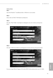
Step 3 Select the "Win7 Folder" from Step1 by clicking the red circle as shown as the picture below . If you are using ASRock's Support CD for the USB 3.0 driver, please select your system. Step 4 Select the "USB Driver Folder" by clicking the red circle as shown as the picture below . Z170M Pro4 Instructions Step 1 Insert the Windows® 7 installation disk or USB drive to your CD-ROM. 41 English Step 2 Extract the tool (Win7 USB Patcher) and launch it.
Step 3 Select the "Win7 Folder" from Step1 by clicking the red circle as shown as the picture below . If you are using ASRock's Support CD for the USB 3.0 driver, please select your system. Step 4 Select the "USB Driver Folder" by clicking the red circle as shown as the picture below . Z170M Pro4 Instructions Step 1 Insert the Windows® 7 installation disk or USB drive to your CD-ROM. 41 English Step 2 Extract the tool (Win7 USB Patcher) and launch it.
User Manual
Page 63
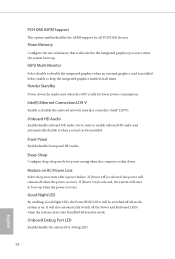
... Keyboard LEDs when the system enters into Standby/Hibernation mode. Onboard Debug Port LED Enable/disable the onboard Dr. Debug LED. 58 English Restore on . Onboard HD Audio Enable/disable onboard HD audio. Render Standby Power down . Inte(R) Ethernet Connection I219-V Enable or disable the onboard network interface controller (Intel® I219V). It will be switched of memory that is selected, the power will start to enable onboard HD audio and automatically disable it when a sound card is installed. Set to Auto to boot up . Deep Sleep Conigure deep sleep mode...
... Keyboard LEDs when the system enters into Standby/Hibernation mode. Onboard Debug Port LED Enable/disable the onboard Dr. Debug LED. 58 English Restore on . Onboard HD Audio Enable/disable onboard HD audio. Render Standby Power down . Inte(R) Ethernet Connection I219-V Enable or disable the onboard network interface controller (Intel® I219V). It will be switched of memory that is selected, the power will start to enable onboard HD audio and automatically disable it when a sound card is installed. Set to Auto to boot up . Deep Sleep Conigure deep sleep mode...
User Manual
Page 65
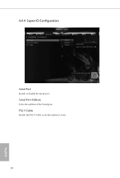
PS2 Y-Cable Enable the PS2 Y-Cable or set this option to Auto. 60 English Serial Port Address Select the address of the Serial port. 4.4.4 Super IO Coniguration Serial Port Enable or disable the Serial port.
PS2 Y-Cable Enable the PS2 Y-Cable or set this option to Auto. 60 English Serial Port Address Select the address of the Serial port. 4.4.4 Super IO Coniguration Serial Port Enable or disable the Serial port.

User Manual
Page 70
... users. 4.5 Tools Z170M Pro4 System Browser ASRock System Browser shows the overview of internet access granted to establish an internet curfew or restrict internet access at speciied times via OMG. Please setup network coniguration before using UEFI Tech Service. Ater copying the drivers please change the SATA mode to modify the system time are having trouble with your current PC and the devices connected. In order to prevent users...
... users. 4.5 Tools Z170M Pro4 System Browser ASRock System Browser shows the overview of internet access granted to establish an internet curfew or restrict internet access at speciied times via OMG. Please setup network coniguration before using UEFI Tech Service. Ater copying the drivers please change the SATA mode to modify the system time are having trouble with your current PC and the devices connected. In order to prevent users...

User Manual
Page 71
... Driver Installer is a handy tool in the UEFI that installs the LAN driver to dehumidify the system ater entering S4/S5 state. 66 English Boot Manager Timeout Enable/disable the Boot Manager Timeout. Timeout Seconds Conigure the number of seconds to wait for the dual OS platform/multi-OS platform users to easily customize and manage the boot menu. *Please connect more than one boot devices to use this...
... Driver Installer is a handy tool in the UEFI that installs the LAN driver to dehumidify the system ater entering S4/S5 state. 66 English Boot Manager Timeout Enable/disable the Boot Manager Timeout. Timeout Seconds Conigure the number of seconds to wait for the dual OS platform/multi-OS platform users to easily customize and manage the boot menu. *Please connect more than one boot devices to use this...

User Manual
Page 73
Network Coniguration Use this to download the UEFI irmware. 68 English Internet Setting Enable or disable sound efects in the setup utility. UEFI Download Server Select a server to conigure internet connection settings for Internet Flash.
Network Coniguration Use this to download the UEFI irmware. 68 English Internet Setting Enable or disable sound efects in the setup utility. UEFI Download Server Select a server to conigure internet connection settings for Internet Flash.

User Manual
Page 76
... authority to enable or disable support for the user account. You may set or change the settings in the UEFI Setup Utility. User Password Set or change the password for the system. Intel(R) Platform Trust Technology Enable/disable Intel PTT in the UEFI Setup Utility. Leave it blank and press enter to remove the password. Users are unable to use discrete TPM Module. 71 English Secure Boot Use this option to change the supervisor/user password for the administrator account. Z170M Pro4 4.7 Security Screen In...
... authority to enable or disable support for the user account. You may set or change the settings in the UEFI Setup Utility. User Password Set or change the password for the system. Intel(R) Platform Trust Technology Enable/disable Intel PTT in the UEFI Setup Utility. Leave it blank and press enter to remove the password. Users are unable to use discrete TPM Module. 71 English Secure Boot Use this option to change the supervisor/user password for the administrator account. Z170M Pro4 4.7 Security Screen In...


