User Manual
Page 7
You may find the latest VGA cards and CPU support list on ASRock's website without notice. In this manual, Chapter 1 and 2 contains the introduction of the software and utilities. Because the motherboard ...any modifications of the BIOS setup. ASRock website http://www.asrock.com. 1.1 Package Contents • ASRock Z87 Extreme4 Motherboard (ATX Form Factor) • ASRock Z87 Extreme4 Quick Installation Guide • ASRock Z87 Extreme4 Support CD • 4 x Serial ATA (SATA) Data Cables (Optional) • 1 x I/O Panel Shield • 1 x ASRock SLI_Bridge_2S Card 1 English Chapter 4...
You may find the latest VGA cards and CPU support list on ASRock's website without notice. In this manual, Chapter 1 and 2 contains the introduction of the software and utilities. Because the motherboard ...any modifications of the BIOS setup. ASRock website http://www.asrock.com. 1.1 Package Contents • ASRock Z87 Extreme4 Motherboard (ATX Form Factor) • ASRock Z87 Extreme4 Quick Installation Guide • ASRock Z87 Extreme4 Support CD • 4 x Serial ATA (SATA) Data Cables (Optional) • 1 x I/O Panel Shield • 1 x ASRock SLI_Bridge_2S Card 1 English Chapter 4...
User Manual
Page 30
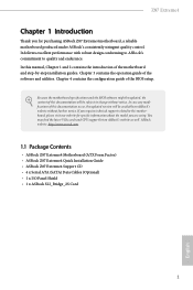
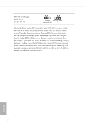
... or BIOS_B_LED) to ensure normal system operation. English 24 After that, short pin1 and pin2 again, then use a jumper cap to update the backup BIOS manually. BIOS Selection Jumper (BIOS_SEL1) (see p.11, No. 16) Default Backup BIOS (Main BIOS) This motherboard has two BIOS onboard, a main BIOS (BIOS_A) and a backup BIOS...
... or BIOS_B_LED) to ensure normal system operation. English 24 After that, short pin1 and pin2 again, then use a jumper cap to update the backup BIOS manually. BIOS Selection Jumper (BIOS_SEL1) (see p.11, No. 16) Default Backup BIOS (Main BIOS) This motherboard has two BIOS onboard, a main BIOS (BIOS_A) and a backup BIOS...
User Manual
Page 33
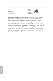
... in our manual and chassis manual to the front audio panel. Chassis and Power Fan Connectors (4-pin CHA_FAN1) (see p.11, No. 26) (3-pin CHA_FAN2) (see p.11, No. 2) (3-pin CHA_FAN3) (see p.11, No. 31) (3-pin PWR_FAN1) (see p.11, No. 15) DUMMY SPEAKER 1 +5V DUMMY Please connect the chassis speaker to OUT2_L. Z87 Extreme4 Front Panel...
... in our manual and chassis manual to the front audio panel. Chassis and Power Fan Connectors (4-pin CHA_FAN1) (see p.11, No. 26) (3-pin CHA_FAN2) (see p.11, No. 2) (3-pin CHA_FAN3) (see p.11, No. 31) (3-pin PWR_FAN1) (see p.11, No. 15) DUMMY SPEAKER 1 +5V DUMMY Please connect the chassis speaker to OUT2_L. Z87 Extreme4 Front Panel...
User Manual
Page 44
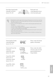
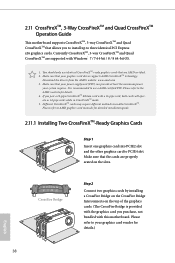
... slot. Download the drivers from the AMD's website: www.amd.com 3. If you purchase, not bundled with this motherboard. Please refer to AMD graphics card manuals for detailed installation guide. 2.11.1 Installing Two CrossFireXTM-Ready Graphics Cards Step 1 Insert one graphics card into PCIE2 slot and the other graphics card to...
... slot. Download the drivers from the AMD's website: www.amd.com 3. If you purchase, not bundled with this motherboard. Please refer to AMD graphics card manuals for detailed installation guide. 2.11.1 Installing Two CrossFireXTM-Ready Graphics Cards Step 1 Insert one graphics card into PCIE2 slot and the other graphics card to...
User Manual
Page 71
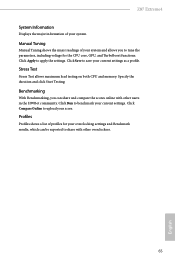
... to share with other overclockers. 65 English Manual Tuning Manual Tuning shows the major readings of your system and allows you can be exported to tune the parameters, including voltage for your current settings as a profile. Profiles Profiles shows a list of your current settings. Z87 Extreme4 System Information Displays the major information of profiles...
... to share with other overclockers. 65 English Manual Tuning Manual Tuning shows the major readings of your system and allows you can be exported to tune the parameters, including voltage for your current settings as a profile. Profiles Profiles shows a list of your current settings. Z87 Extreme4 System Information Displays the major information of profiles...
User Manual
Page 83
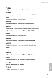
tRDRDDD Use this to change DRAM tRWSR Auto/Manual settings. tWRRDDR Configure between module write to read to write delay from different DIMMs. RTL (CHA) Configure round trip latency for channel B. 77 English tWRWRDR ... A. tWRRDDD Use this to change DRAM tRRSR Auto/Manual settings. tRDWRDR Configure between module read delay from different ranks. The default is [Auto]. Configure between module write to read to write delay from different DIMMs. tWRWR Configure between module write to write delay. Z87 Extreme4 tRDRDDR Configure between module read to read delay...
tRDRDDD Use this to change DRAM tRWSR Auto/Manual settings. tWRRDDR Configure between module write to read to write delay from different DIMMs. RTL (CHA) Configure round trip latency for channel B. 77 English tWRWRDR ... A. tWRRDDD Use this to change DRAM tRRSR Auto/Manual settings. tRDWRDR Configure between module read delay from different ranks. The default is [Auto]. Configure between module write to read to write delay from different DIMMs. tWRWR Configure between module write to write delay. Z87 Extreme4 tRDRDDR Configure between module read to read delay...
User Manual
Page 84
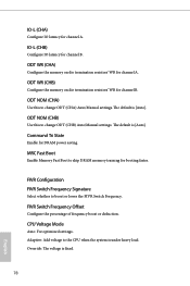
...system is fixed. 78 English IO-L (CHA) Configure IO latency for channel B. ODT NOM (CHA) Use this to change ODT (CHA) Auto/Manual settings. ODT WR (CHB) Configure the memory on die termination resistors' WR for channel B. Command Tri State Enable for booting faster. MRC Fast... Boot Enable Memory Fast Boot to change ODT (CHB) Auto/Manual settings. The default is [Auto]. IO-L (CHB) Configure IO latency for channel A. Adaptive: Add voltage to boost or lower the FIVR Switch...
...system is fixed. 78 English IO-L (CHA) Configure IO latency for channel B. ODT NOM (CHA) Use this to change ODT (CHA) Auto/Manual settings. ODT WR (CHB) Configure the memory on die termination resistors' WR for channel B. Command Tri State Enable for booting faster. MRC Fast... Boot Enable Memory Fast Boot to change ODT (CHB) Auto/Manual settings. The default is [Auto]. IO-L (CHB) Configure IO latency for channel A. Adaptive: Add voltage to boost or lower the FIVR Switch...
Quick Installation Guide
Page 26
... Normally, the system works on the next system boot. After that, short pin1 and pin2 again, then use a jumper cap to update the backup BIOS manually. BIOS Selection Jumper (BIOS_SEL1) (see p.1, No. 16) Default Backup BIOS (Main BIOS) This motherboard has two BIOS onboard, a main BIOS (BIOS_A) and a backup BIOS (BIOS_B...
... Normally, the system works on the next system boot. After that, short pin1 and pin2 again, then use a jumper cap to update the backup BIOS manually. BIOS Selection Jumper (BIOS_SEL1) (see p.1, No. 16) Default Backup BIOS (Main BIOS) This motherboard has two BIOS onboard, a main BIOS (BIOS_A) and a backup BIOS (BIOS_B...
Quick Installation Guide
Page 29
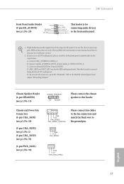
...install your system. 2. Connect Ground (GND) to OUT2_L. B. To activate the front mic, go to the "FrontMic" Tab in our manual and chassis manual to this header. GND +12V FAN_SPEED English 27 Connect Audio_R (RIN) to OUT2_R and Audio_L (LIN) to Ground (GND). MIC_RET and ...A. If you use an AC'97 audio panel, please install it to function correctly. Connect Mic_IN (MIC) to the front audio panel. E. C. Z87 Extreme4 Front Panel Audio Header GN D (9-pin HD_AUDIO1) (see p.1, No. 29) PRESENCE# MIC_RET OUT_RET OUT2_L This header is for J_SENSE connecting audio devices ...
...install your system. 2. Connect Ground (GND) to OUT2_L. B. To activate the front mic, go to the "FrontMic" Tab in our manual and chassis manual to this header. GND +12V FAN_SPEED English 27 Connect Audio_R (RIN) to OUT2_R and Audio_L (LIN) to Ground (GND). MIC_RET and ...A. If you use an AC'97 audio panel, please install it to function correctly. Connect Mic_IN (MIC) to the front audio panel. E. C. Z87 Extreme4 Front Panel Audio Header GN D (9-pin HD_AUDIO1) (see p.1, No. 29) PRESENCE# MIC_RET OUT_RET OUT2_L This header is for J_SENSE connecting audio devices ...
