User Manual
Page 11
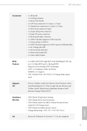
... (IXTU) Hardware Monitor • CPU/Chassis Temperature Sensing • CPU/Chassis/Power Fan Tachometer • CPU/Chassis Quiet Fan (Allow Chassis Fan Speed Auto- Z87 Extreme4 Connector • 1 x IR header • 1 x COM port header • 1 x Power LED header • 2 x CPU Fan connectors (1 ... • 1 x Power Switch with LED • 1 x Reset Switch with LED • 1 x Clear CMOS Switch BIOS Feature • 2 x 64Mb AMI UEFI Legal BIOS with Multilingual GUI support (1 x Main BIOS and 1 x Backup BIOS) • Supports Secure Backup UEFI Technology • ACPI 1.1 Compliance...
... (IXTU) Hardware Monitor • CPU/Chassis Temperature Sensing • CPU/Chassis/Power Fan Tachometer • CPU/Chassis Quiet Fan (Allow Chassis Fan Speed Auto- Z87 Extreme4 Connector • 1 x IR header • 1 x COM port header • 1 x Power LED header • 2 x CPU Fan connectors (1 ... • 1 x Power Switch with LED • 1 x Reset Switch with LED • 1 x Clear CMOS Switch BIOS Feature • 2 x 64Mb AMI UEFI Legal BIOS with Multilingual GUI support (1 x Main BIOS and 1 x Backup BIOS) • Supports Secure Backup UEFI Technology • ACPI 1.1 Compliance...
User Manual
Page 17
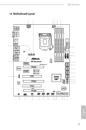
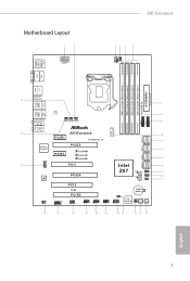
1.4 Motherboard Layout 1 2 ATX12V1 Z87 Extreme4 34 5 6 CPU_FAN2 CPU_FAN1 USB 2.0 T: USB0 B: USB1 PS2 ...SPK Bottom: Optical SPDIF Top: Center: FRONT Bottom: MIC IN USB3_8 Vertical Type A USB SATA3_A0_A1 30 Z87 Extreme4 10 PCIE1 PCI Express 3.0 11 Purity SoundTM HD_AUDIO1 PCIE3 PCIE2 XFast RAM XFast LAN XFast USB 29 PCI1 ...1 Super I/O PCIE4 12 SATA3_2_3 13 SATA3_4_5 Intel 14 Z87 BIOS_B_LED 64Mb BIOS BIOS_B BIOS_A_LED 64Mb BIOS BIOS_A SPEAKER1 1 BIOS_SEL1 1 CLRCMOS1 1 15 16 17 SATA3_0_1 PCI2 IR1 1 COM1 1 RoHS PCIE5 ...
1.4 Motherboard Layout 1 2 ATX12V1 Z87 Extreme4 34 5 6 CPU_FAN2 CPU_FAN1 USB 2.0 T: USB0 B: USB1 PS2 ...SPK Bottom: Optical SPDIF Top: Center: FRONT Bottom: MIC IN USB3_8 Vertical Type A USB SATA3_A0_A1 30 Z87 Extreme4 10 PCIE1 PCI Express 3.0 11 Purity SoundTM HD_AUDIO1 PCIE3 PCIE2 XFast RAM XFast LAN XFast USB 29 PCI1 ...1 Super I/O PCIE4 12 SATA3_2_3 13 SATA3_4_5 Intel 14 Z87 BIOS_B_LED 64Mb BIOS BIOS_B BIOS_A_LED 64Mb BIOS BIOS_A SPEAKER1 1 BIOS_SEL1 1 CLRCMOS1 1 15 16 17 SATA3_0_1 PCI2 IR1 1 COM1 1 RoHS PCIE5 ...
User Manual
Page 18
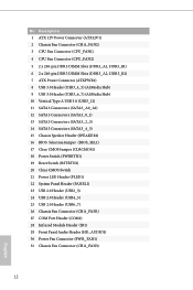
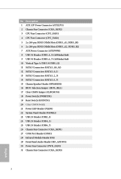
...) 12 SATA3 Connectors (SATA3_0_1) 13 SATA3 Connectors (SATA3_2_3) 14 SATA3 Connectors (SATA3_4_5) 15 Chassis Speaker Header (SPEAKER1) 16 BIOS Selection Jumper (BIOS_SEL1) 17 Clear CMOS Jumper (CLRCMOS1) 18 Power Switch (PWRBTN1) 19 Reset Switch (RSTBTN1) 20 Clear CMOS Switch 21 Power LED Header (PLED1) 22 System Panel Header (PANEL1) 23 USB 2.0 Header...
...) 12 SATA3 Connectors (SATA3_0_1) 13 SATA3 Connectors (SATA3_2_3) 14 SATA3 Connectors (SATA3_4_5) 15 Chassis Speaker Header (SPEAKER1) 16 BIOS Selection Jumper (BIOS_SEL1) 17 Clear CMOS Jumper (CLRCMOS1) 18 Power Switch (PWRBTN1) 19 Reset Switch (RSTBTN1) 20 Clear CMOS Switch 21 Power LED Header (PLED1) 22 System Panel Header (PANEL1) 23 USB 2.0 Header...
User Manual
Page 29
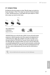
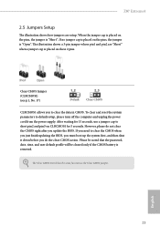
.... Clear CMOS Jumper (CLRCMOS1) (see p.11, No. 17) Default Clear CMOS CLRCMOS1 allows you update the BIOS. English 23 The illustration shows a 3-pin jumper whose pin1 and pin2 are setup. To clear and reset the system parameters to short pin2 and pin3 on CLRCMOS1 for 15 seconds, use a jumper cap to... jumper cap is placed on the pins, the jumper is "Open". If no jumper cap is placed on the pins, the jumper is "Short". Z87 Extreme4 2.5 Jumpers Setup The illustration shows how jumpers are "Short" when a jumper cap is placed on these 2 pins. After waiting for 5 seconds.
.... Clear CMOS Jumper (CLRCMOS1) (see p.11, No. 17) Default Clear CMOS CLRCMOS1 allows you update the BIOS. English 23 The illustration shows a 3-pin jumper whose pin1 and pin2 are setup. To clear and reset the system parameters to short pin2 and pin3 on CLRCMOS1 for 15 seconds, use a jumper cap to... jumper cap is placed on the pins, the jumper is "Open". If no jumper cap is placed on the pins, the jumper is "Short". Z87 Extreme4 2.5 Jumpers Setup The illustration shows how jumpers are "Short" when a jumper cap is placed on these 2 pins. After waiting for 5 seconds.
User Manual
Page 75
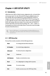
...UEFI setup screens and descriptions are for reference purpose only, and they may not exactly match what you power on your system. Z87 Extreme4 Chapter 4 UEFI SETUP UTILITY 4.1 Introduction ASRock Interactive UEFI is constantly being updated, the following selections: Main For setting system time/date information OC Tweaker For overclocking configurations ... Utility to enter the UEFI Setup Utility after you see on the computer, otherwise, the Power-On-Self-Test (POST) will it make BIOS setup less difficult but also a lot more amusing. You may also restart by pressing the...
...UEFI setup screens and descriptions are for reference purpose only, and they may not exactly match what you power on your system. Z87 Extreme4 Chapter 4 UEFI SETUP UTILITY 4.1 Introduction ASRock Interactive UEFI is constantly being updated, the following selections: Main For setting system time/date information OC Tweaker For overclocking configurations ... Utility to enter the UEFI Setup Utility after you see on the computer, otherwise, the Power-On-Self-Test (POST) will it make BIOS setup less difficult but also a lot more amusing. You may also restart by pressing the...
Quick Installation Guide
Page 3
Motherboard Layout 1 2 ATX12V1 Z87 Extreme4 34 5 6 CPU_FAN2 CPU_FAN1 USB 2.0 T: USB0 B: USB1 PS2 ...SPK Bottom: Optical SPDIF Top: Center: FRONT Bottom: MIC IN USB3_8 Vertical Type A USB SATA3_A0_A1 30 Z87 Extreme4 10 PCIE1 PCI Express 3.0 11 Purity SoundTM HD_AUDIO1 PCIE3 PCIE2 XFast RAM XFast LAN XFast USB 29 PCI1 ...1 Super I/O PCIE4 12 SATA3_2_3 13 SATA3_4_5 Intel 14 Z87 BIOS_B_LED 64Mb BIOS BIOS_B BIOS_A_LED 64Mb BIOS BIOS_A SPEAKER1 1 BIOS_SEL1 1 CLRCMOS1 1 15 16 17 SATA3_0_1 PCI2 IR1 1 COM1 1 RoHS PCIE5 ...
Motherboard Layout 1 2 ATX12V1 Z87 Extreme4 34 5 6 CPU_FAN2 CPU_FAN1 USB 2.0 T: USB0 B: USB1 PS2 ...SPK Bottom: Optical SPDIF Top: Center: FRONT Bottom: MIC IN USB3_8 Vertical Type A USB SATA3_A0_A1 30 Z87 Extreme4 10 PCIE1 PCI Express 3.0 11 Purity SoundTM HD_AUDIO1 PCIE3 PCIE2 XFast RAM XFast LAN XFast USB 29 PCI1 ...1 Super I/O PCIE4 12 SATA3_2_3 13 SATA3_4_5 Intel 14 Z87 BIOS_B_LED 64Mb BIOS BIOS_B BIOS_A_LED 64Mb BIOS BIOS_A SPEAKER1 1 BIOS_SEL1 1 CLRCMOS1 1 15 16 17 SATA3_0_1 PCI2 IR1 1 COM1 1 RoHS PCIE5 ...
Quick Installation Guide
Page 4
...) 12 SATA3 Connectors (SATA3_0_1) 13 SATA3 Connectors (SATA3_2_3) 14 SATA3 Connectors (SATA3_4_5) 15 Chassis Speaker Header (SPEAKER1) 16 BIOS Selection Jumper (BIOS_SEL1) 17 Clear CMOS Jumper (CLRCMOS1) 18 Power Switch (PWRBTN1) 19 Reset Switch (RSTBTN1) 20 Clear CMOS Switch 21 Power LED Header (PLED1) 22 System Panel Header (PANEL1) 23 USB 2.0 Header...
...) 12 SATA3 Connectors (SATA3_0_1) 13 SATA3 Connectors (SATA3_2_3) 14 SATA3 Connectors (SATA3_4_5) 15 Chassis Speaker Header (SPEAKER1) 16 BIOS Selection Jumper (BIOS_SEL1) 17 Clear CMOS Jumper (CLRCMOS1) 18 Power Switch (PWRBTN1) 19 Reset Switch (RSTBTN1) 20 Clear CMOS Switch 21 Power LED Header (PLED1) 22 System Panel Header (PANEL1) 23 USB 2.0 Header...

Quick Installation Guide
Page 11
... (IXTU) Hardware Monitor • CPU/Chassis Temperature Sensing • CPU/Chassis/Power Fan Tachometer • CPU/Chassis Quiet Fan (Allow Chassis Fan Speed Auto- Z87 Extreme4 Connector • 1 x IR header • 1 x COM port header • 1 x Power LED header • 2 x CPU Fan connectors (1 ... • 1 x Power Switch with LED • 1 x Reset Switch with LED • 1 x Clear CMOS Switch BIOS Feature • 2 x 64Mb AMI UEFI Legal BIOS with Multilingual GUI support (1 x Main BIOS and 1 x Backup BIOS) • Supports Secure Backup UEFI Technology • ACPI 1.1 Compliance...
... (IXTU) Hardware Monitor • CPU/Chassis Temperature Sensing • CPU/Chassis/Power Fan Tachometer • CPU/Chassis Quiet Fan (Allow Chassis Fan Speed Auto- Z87 Extreme4 Connector • 1 x IR header • 1 x COM port header • 1 x Power LED header • 2 x CPU Fan connectors (1 ... • 1 x Power Switch with LED • 1 x Reset Switch with LED • 1 x Clear CMOS Switch BIOS Feature • 2 x 64Mb AMI UEFI Legal BIOS with Multilingual GUI support (1 x Main BIOS and 1 x Backup BIOS) • Supports Secure Backup UEFI Technology • ACPI 1.1 Compliance...
Quick Installation Guide
Page 25
Z87 Extreme4 2.5 Jumpers Setup The illustration shows how jumpers are "Short" when a jumper cap is placed on the pins, the jumper... you to default setup, please turn off the computer and unplug the power cord from the power supply. To clear and reset the system parameters to clear the data in CMOS. English 23 Please be noted that the password, date, time, and ...for 5 seconds. After waiting for 15 seconds, use a jumper cap to clear the CMOS when you just finish updating the BIOS, you must boot up the system first, and then shut it down before you do not clear the CMOS right after you...
Z87 Extreme4 2.5 Jumpers Setup The illustration shows how jumpers are "Short" when a jumper cap is placed on the pins, the jumper... you to default setup, please turn off the computer and unplug the power cord from the power supply. To clear and reset the system parameters to clear the data in CMOS. English 23 Please be noted that the password, date, time, and ...for 5 seconds. After waiting for 15 seconds, use a jumper cap to clear the CMOS when you just finish updating the BIOS, you must boot up the system first, and then shut it down before you do not clear the CMOS right after you...


