User Manual
Page 11
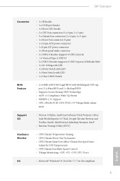
... Control • Voltage Monitoring: +12V, +5V, +3.3V, CPU Vcore OS • Microsoft® Windows® 8 / 8 64-bit / 7 / 7 64-bit compliant 5 English Z87 Extreme4 Connector • 1 x IR header • 1 x COM port header • 1 x Power LED header • 2 x CPU Fan connectors (1 x 4-pin, 1 x 3-pin)... Hub) • 1 x Dr. Debug with LED • 1 x Power Switch with LED • 1 x Reset Switch with LED • 1 x Clear CMOS Switch BIOS Feature • 2 x 64Mb AMI UEFI Legal BIOS with Multilingual GUI support (1 x Main BIOS and 1 x Backup BIOS) • Supports Secure Backup...
... Control • Voltage Monitoring: +12V, +5V, +3.3V, CPU Vcore OS • Microsoft® Windows® 8 / 8 64-bit / 7 / 7 64-bit compliant 5 English Z87 Extreme4 Connector • 1 x IR header • 1 x COM port header • 1 x Power LED header • 2 x CPU Fan connectors (1 x 4-pin, 1 x 3-pin)... Hub) • 1 x Dr. Debug with LED • 1 x Power Switch with LED • 1 x Reset Switch with LED • 1 x Clear CMOS Switch BIOS Feature • 2 x 64Mb AMI UEFI Legal BIOS with Multilingual GUI support (1 x Main BIOS and 1 x Backup BIOS) • Supports Secure Backup...
User Manual
Page 18
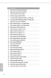
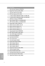
... (SATA3_0_1) 13 SATA3 Connectors (SATA3_2_3) 14 SATA3 Connectors (SATA3_4_5) 15 Chassis Speaker Header (SPEAKER1) 16 BIOS Selection Jumper (BIOS_SEL1) 17 Clear CMOS Jumper (CLRCMOS1) 18 Power Switch (PWRBTN1) 19 Reset Switch (RSTBTN1) 20 Clear CMOS Switch 21 Power LED Header (PLED1) 22 System Panel Header (PANEL1) 23 USB 2.0 Header (USB2_3) 24 USB 2.0 Header (USB4_5...
... (SATA3_0_1) 13 SATA3 Connectors (SATA3_2_3) 14 SATA3 Connectors (SATA3_4_5) 15 Chassis Speaker Header (SPEAKER1) 16 BIOS Selection Jumper (BIOS_SEL1) 17 Clear CMOS Jumper (CLRCMOS1) 18 Power Switch (PWRBTN1) 19 Reset Switch (RSTBTN1) 20 Clear CMOS Switch 21 Power LED Header (PLED1) 22 System Panel Header (PANEL1) 23 USB 2.0 Header (USB2_3) 24 USB 2.0 Header (USB4_5...
User Manual
Page 29
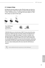
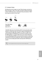
...and user default profile will be cleared only if the CMOS battery is "Short". English 23 When the jumper cap is placed on the pins, the jumper is removed. The illustration shows a 3-pin jumper whose pin1 and pin2 are setup. Z87 Extreme4 2.5 Jumpers Setup The illustration shows... how jumpers are "Short" when a jumper cap is "Open". Clear CMOS Jumper (CLRCMOS1) (see p.11, No. 17) Default Clear CMOS CLRCMOS1 allows you to default setup, please turn off the computer...
...and user default profile will be cleared only if the CMOS battery is "Short". English 23 When the jumper cap is placed on the pins, the jumper is removed. The illustration shows a 3-pin jumper whose pin1 and pin2 are setup. Z87 Extreme4 2.5 Jumpers Setup The illustration shows... how jumpers are "Short" when a jumper cap is "Open". Clear CMOS Jumper (CLRCMOS1) (see p.11, No. 17) Default Clear CMOS CLRCMOS1 allows you to default setup, please turn off the computer...
User Manual
Page 35
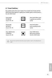
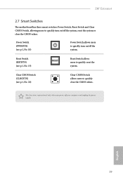
... on /off the system, reset the system or clear the CMOS values. This function is operational only when you power off the system. Clear CMOS Switch (CLRCBTN) (see p.11, No. 19) Reset Switch allows users to quickly turn on /off your computer and unplug the power supply. Z87 Extreme4 2.7 Smart Switches The motherboard has three smart...
... on /off the system, reset the system or clear the CMOS values. This function is operational only when you power off the system. Clear CMOS Switch (CLRCBTN) (see p.11, No. 19) Reset Switch allows users to quickly turn on /off your computer and unplug the power supply. Z87 Extreme4 2.7 Smart Switches The motherboard has three smart...
User Manual
Page 36
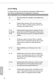
...re-install the CPU and memory. Please re-install the CPU and memory then clear CMOS. Please press reset or clear CMOS. 92 - 99 Problem related to memory. If the problem still exists, please clear CMOS and try removing all PCI-E devices or try using another VGA card. Code ...problem still exists, please install only one memory module or try using other memory modules. 61 - 91 Chipset initialization error. Please clear CMOS, re-install the memory and VGA card, and remove other memory modules. If the problem still exists, please install only one memory...
...re-install the CPU and memory. Please re-install the CPU and memory then clear CMOS. Please press reset or clear CMOS. 92 - 99 Problem related to memory. If the problem still exists, please clear CMOS and try removing all PCI-E devices or try using another VGA card. Code ...problem still exists, please install only one memory module or try using other memory modules. 61 - 91 Chipset initialization error. Please clear CMOS, re-install the memory and VGA card, and remove other memory modules. If the problem still exists, please install only one memory...
User Manual
Page 37
... is installed correctly and then clear CMOS. b7 Problem related to USB devices. d8 Invalid Password. d6 The VGA could not be recognized. English 31 Please re-install the CPU and memory then clear CMOS. Please clear CMOS and try installing the VGA card in other slots or use other memory modules. Z87 Extreme4 b4 Problem related to...
... is installed correctly and then clear CMOS. b7 Problem related to USB devices. d8 Invalid Password. d6 The VGA could not be recognized. English 31 Please re-install the CPU and memory then clear CMOS. Please clear CMOS and try installing the VGA card in other slots or use other memory modules. Z87 Extreme4 b4 Problem related to...
User Manual
Page 104
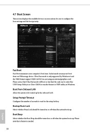
Please notice that Ultra Fast mode will boot so fast that a buzzer is needed. 98 English Ultra Fast mode is to Clear CMOS or run the Restart to UEFI utility in Windows. Bootup Num-Lock Select whether Num Lock should be turned on or off when the system ...
Please notice that Ultra Fast mode will boot so fast that a buzzer is needed. 98 English Ultra Fast mode is to Clear CMOS or run the Restart to UEFI utility in Windows. Bootup Num-Lock Select whether Num Lock should be turned on or off when the system ...
Quick Installation Guide
Page 4
... (SATA3_0_1) 13 SATA3 Connectors (SATA3_2_3) 14 SATA3 Connectors (SATA3_4_5) 15 Chassis Speaker Header (SPEAKER1) 16 BIOS Selection Jumper (BIOS_SEL1) 17 Clear CMOS Jumper (CLRCMOS1) 18 Power Switch (PWRBTN1) 19 Reset Switch (RSTBTN1) 20 Clear CMOS Switch 21 Power LED Header (PLED1) 22 System Panel Header (PANEL1) 23 USB 2.0 Header (USB2_3) 24 USB 2.0 Header (USB4_5...
... (SATA3_0_1) 13 SATA3 Connectors (SATA3_2_3) 14 SATA3 Connectors (SATA3_4_5) 15 Chassis Speaker Header (SPEAKER1) 16 BIOS Selection Jumper (BIOS_SEL1) 17 Clear CMOS Jumper (CLRCMOS1) 18 Power Switch (PWRBTN1) 19 Reset Switch (RSTBTN1) 20 Clear CMOS Switch 21 Power LED Header (PLED1) 22 System Panel Header (PANEL1) 23 USB 2.0 Header (USB2_3) 24 USB 2.0 Header (USB4_5...

Quick Installation Guide
Page 11
... Utility (IXTU) Hardware Monitor • CPU/Chassis Temperature Sensing • CPU/Chassis/Power Fan Tachometer • CPU/Chassis Quiet Fan (Allow Chassis Fan Speed Auto- Z87 Extreme4 Connector • 1 x IR header • 1 x COM port header • 1 x Power LED header • 2 x CPU Fan connectors (1 x 4-...Hub) • 1 x Dr. Debug with LED • 1 x Power Switch with LED • 1 x Reset Switch with LED • 1 x Clear CMOS Switch BIOS Feature • 2 x 64Mb AMI UEFI Legal BIOS with Multilingual GUI support (1 x Main BIOS and 1 x Backup BIOS) • Supports Secure ...
... Utility (IXTU) Hardware Monitor • CPU/Chassis Temperature Sensing • CPU/Chassis/Power Fan Tachometer • CPU/Chassis Quiet Fan (Allow Chassis Fan Speed Auto- Z87 Extreme4 Connector • 1 x IR header • 1 x COM port header • 1 x Power LED header • 2 x CPU Fan connectors (1 x 4-...Hub) • 1 x Dr. Debug with LED • 1 x Power Switch with LED • 1 x Reset Switch with LED • 1 x Clear CMOS Switch BIOS Feature • 2 x 64Mb AMI UEFI Legal BIOS with Multilingual GUI support (1 x Main BIOS and 1 x Backup BIOS) • Supports Secure ...
Quick Installation Guide
Page 25
...the system parameters to short pin2 and pin3 on the pins, the jumper is "Open". Clear CMOS Jumper (CLRCMOS1) (see p.1, No. 17) Default Clear CMOS CLRCMOS1 allows you update the BIOS. However, please do the clear-CMOS action. The illustration shows a 3-pin jumper whose pin1 and pin2 are setup. Please ... the BIOS, you must boot up the system first, and then shut it down before you do not clear the CMOS right after you to clear the data in CMOS. English 23 Z87 Extreme4 2.5 Jumpers Setup The illustration shows how jumpers are "Short" when a jumper cap is placed on the ...
...the system parameters to short pin2 and pin3 on the pins, the jumper is "Open". Clear CMOS Jumper (CLRCMOS1) (see p.1, No. 17) Default Clear CMOS CLRCMOS1 allows you update the BIOS. However, please do the clear-CMOS action. The illustration shows a 3-pin jumper whose pin1 and pin2 are setup. Please ... the BIOS, you must boot up the system first, and then shut it down before you do not clear the CMOS right after you to clear the data in CMOS. English 23 Z87 Extreme4 2.5 Jumpers Setup The illustration shows how jumpers are "Short" when a jumper cap is placed on the ...
Quick Installation Guide
Page 31
... allows users to quickly turn on /off the system, reset the system or clear the CMOS values. Z87 Extreme4 2.7 Smart Switches The motherboard has three smart switches: Power Switch, Reset Switch and Clear CMOS Switch, allowing users to quickly clear the CMOS values. Clear CMOS Switch (CLRCBTN) (see p.1, No. 19) Reset Switch allows users to quickly turn on /off your...
... allows users to quickly turn on /off the system, reset the system or clear the CMOS values. Z87 Extreme4 2.7 Smart Switches The motherboard has three smart switches: Power Switch, Reset Switch and Clear CMOS Switch, allowing users to quickly clear the CMOS values. Clear CMOS Switch (CLRCBTN) (see p.1, No. 19) Reset Switch allows users to quickly turn on /off your...

