

AL1702 Service Guide
Page 4
Checking inverter board circuit 23 12. Power board 24 3) Spare Parts Recommended Spare Parts List 25 Page 2 Checking the Audio circuit [option 22 11. Checking the interface circuit of sync signal 19 7.1 Checking the control circuit of horizontal sync pulse 19 7.2 Checking the control circuit of vertical sync pulse 19 8 Checking the resolution change IC movement 20 9. AL1702 6. Abnormal plug and play operation 18 7. Checking the DC/DC converter circuit 21 10.
Checking inverter board circuit 23 12. Power board 24 3) Spare Parts Recommended Spare Parts List 25 Page 2 Checking the Audio circuit [option 22 11. Checking the interface circuit of sync signal 19 7.1 Checking the control circuit of horizontal sync pulse 19 7.2 Checking the control circuit of vertical sync pulse 19 8 Checking the resolution change IC movement 20 9. AL1702 6. Abnormal plug and play operation 18 7. Checking the DC/DC converter circuit 21 10.

AL1702 Service Guide
Page 10
Table 2 video mode Mode Resolution 1 720x400 (70Hz) 2 640x480 (59.94Hz) 3 640x480 (66.67Hz) 4 640x480 (72Hz) 5 640x480 (75Hz) 6 800x600 (56.25Hz) 7 800x600 (60Hz) 8 800x600 (72Hz) 9 800x600 (75Hz) 10 832x624 (74.55Hz) ....322 25.175 30.24 31.5 31.5 36 40 50 49.5 57.28 65 75 78.75 108 108 108 135 Polarity H V AL1702 Table 3 the Hsync, Vsync distinction Indication resolution 720 x 400 640 x 480 800 x 600 832 x 624 1024 x 768 1152 x 864 1280 x 960 1280 x 1024 1280 x 1024 Distinction Hsync 30.5KHz...
Table 2 video mode Mode Resolution 1 720x400 (70Hz) 2 640x480 (59.94Hz) 3 640x480 (66.67Hz) 4 640x480 (72Hz) 5 640x480 (75Hz) 6 800x600 (56.25Hz) 7 800x600 (60Hz) 8 800x600 (72Hz) 9 800x600 (75Hz) 10 832x624 (74.55Hz) ....322 25.175 30.24 31.5 31.5 36 40 50 49.5 57.28 65 75 78.75 108 108 108 135 Polarity H V AL1702 Table 3 the Hsync, Vsync distinction Indication resolution 720 x 400 640 x 480 800 x 600 832 x 624 1024 x 768 1152 x 864 1280 x 960 1280 x 1024 1280 x 1024 Distinction Hsync 30.5KHz...

AL1702 Service Guide
Page 13
NG OK Input the sync signal of computer, or change IC movement" section. Page 11 Proceed "No OSM display" section. No display of screen (Screen is amber) AL1702 Does OSM display when you push PROCEED buttom. No When a sugnal isn't being inputed, it is indicated with "VIDEO INPUT". it is connected normally. Check if the sync signal from computer is output and if the video cable is indicated with "OUT OIF RANGE" at the Yes time of LED is black, color of the frequency that it can't be distinguished. Proceed "checking the resolution change the cable. 1.
NG OK Input the sync signal of computer, or change IC movement" section. Page 11 Proceed "No OSM display" section. No display of screen (Screen is amber) AL1702 Does OSM display when you push PROCEED buttom. No When a sugnal isn't being inputed, it is indicated with "VIDEO INPUT". it is connected normally. Check if the sync signal from computer is output and if the video cable is indicated with "OUT OIF RANGE" at the Yes time of LED is black, color of the frequency that it can't be distinguished. Proceed "checking the resolution change the cable. 1.

AL1702 Service Guide
Page 18
... between P302 pin 9 and I305 pin63. 2) Video cable is failure. 3) R322 is short or open. 4) R318 is short or open . Prpcess "Checking the resolution change IC movement" section. Check the R, G, B input video signals on P302 of the Red signal. (A Green and Blue signal is the same path, too....) 1)Printed wire broke between I305 and P305. 4. Abnormal screen AL1702 Check the R, G, B video signal from host computer, check computer. 2) Video signal cable disconnection. NG OK Check all LVDS signals being output to 0.7Vp-p.
... between P302 pin 9 and I305 pin63. 2) Video cable is failure. 3) R322 is short or open. 4) R318 is short or open . Prpcess "Checking the resolution change IC movement" section. Check the R, G, B input video signals on P302 of the Red signal. (A Green and Blue signal is the same path, too....) 1)Printed wire broke between I305 and P305. 4. Abnormal screen AL1702 Check the R, G, B video signal from host computer, check computer. 2) Video signal cable disconnection. NG OK Check all LVDS signals being output to 0.7Vp-p.

AL1702 Service Guide
Page 21
...Checking the control circuit of vertical sync pluse Check the horizontal sync signal on P302 pin3 TTL level. NG OK Failure Point Process "Checking the resolution change IC movement" section. Failure Point 1) Printed wire broke between P302 pin3 and I305 pin36. 2) FB312, R328 open . 3) R331, ...C346 short. 7.2 Checking the control circuit of horizontal sync pluse AL1702 Check the horizontal sync signal on P302 pin2 TTL level. Failure Point 1) Printed wire broke between P302 pin3 and I305 pin37. 2) FB313, R329 open...
...Checking the control circuit of vertical sync pluse Check the horizontal sync signal on P302 pin3 TTL level. NG OK Failure Point Process "Checking the resolution change IC movement" section. Failure Point 1) Printed wire broke between P302 pin3 and I305 pin36. 2) FB312, R328 open . 3) R331, ...C346 short. 7.2 Checking the control circuit of horizontal sync pluse AL1702 Check the horizontal sync signal on P302 pin2 TTL level. Failure Point 1) Printed wire broke between P302 pin3 and I305 pin37. 2) FB313, R329 open...

AL1702 Service Guide
Page 22
... Point 1) Printed wire broke between X301 and I305 pin33, 34. 2) C371, C375 short or open . 3) I307 failure. Failure Point I305 failure. Checking the resolution change IC movement AL1702 Check +3.3V supply on I305 pin18, 87, 97, 117. NG OK Failure Point 1) Printed wire broke between I305 pin69, 70, 71 and I307 pin20...
... Point 1) Printed wire broke between X301 and I305 pin33, 34. 2) C371, C375 short or open . 3) I307 failure. Failure Point I305 failure. Checking the resolution change IC movement AL1702 Check +3.3V supply on I305 pin18, 87, 97, 117. NG OK Failure Point 1) Printed wire broke between I305 pin69, 70, 71 and I307 pin20...
AL1702W Service Guide
Page 7
... also a space saving design, allowing more . Monitor Features Chapter 1 Introduction Scope This specification defines the requirements for the 17" MICROPROCESSOR based Multi-mode supported high resolution color LCD monitor. This will alleviate the growing health concerns. There is a build-in addition MTBF target is designed with the latest LCD technology to...
... also a space saving design, allowing more . Monitor Features Chapter 1 Introduction Scope This specification defines the requirements for the 17" MICROPROCESSOR based Multi-mode supported high resolution color LCD monitor. This will alleviate the growing health concerns. There is a build-in addition MTBF target is designed with the latest LCD technology to...
AL1702W Service Guide
Page 26
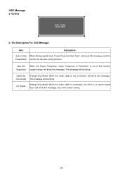
Input Not Supported When the Hsync Frequency, Vsync Frequency or Resolution is out of the monitor support range, will show this message. Cable Not Analog-Only Model: When the video cable is no active signal input, ...
Input Not Supported When the Hsync Frequency, Vsync Frequency or Resolution is out of the monitor support range, will show this message. Cable Not Analog-Only Model: When the video cable is no active signal input, ...
AL1702W User's Guide
Page 4
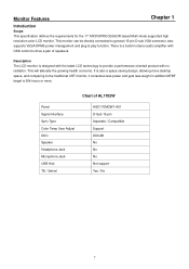
....99% or more. LCD Monitor 2. BEFORE YOU OPERATE THE MONITOR FEATURES • 17"W TFT Color LCD Monitor • Crisp, Clear Display for Windows • Recommened Resolutions: 1440 X 900 @60Hz • EPA ENERGY STAR® • Ergonomic Design • Space Saving, Compact Case Design CHECKING THE CONTENTS OF THE PACKAGE The product...
....99% or more. LCD Monitor 2. BEFORE YOU OPERATE THE MONITOR FEATURES • 17"W TFT Color LCD Monitor • Crisp, Clear Display for Windows • Recommened Resolutions: 1440 X 900 @60Hz • EPA ENERGY STAR® • Ergonomic Design • Space Saving, Compact Case Design CHECKING THE CONTENTS OF THE PACKAGE The product...
AL1702W User's Guide
Page 12
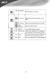
Position Adjust the horizontal position of current iput timing. H. OSD Timeout Adjust the OSD timeout. N/A Information Show the resolution, H/V frequency and input port of the OSD. Position Adjust the vertical position of Auto-configuration and set the color temperature to Cool. N/A DDC/CI Turn ON/OFF DDC/CI support. V. N/A Reset Clear each old status of the OSD. N/A Exit Save user adjustment and OSD disappear. 11 N/A Language Multi-language selection.
Position Adjust the horizontal position of current iput timing. H. OSD Timeout Adjust the OSD timeout. N/A Information Show the resolution, H/V frequency and input port of the OSD. Position Adjust the vertical position of Auto-configuration and set the color temperature to Cool. N/A DDC/CI Turn ON/OFF DDC/CI support. V. N/A Reset Clear each old status of the OSD. N/A Exit Save user adjustment and OSD disappear. 11 N/A Language Multi-language selection.
AL1702W User's Guide
Page 17
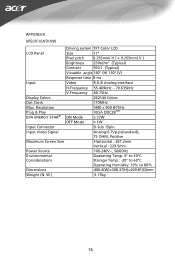
...; (V) Response time 8 ms Input Video R,G,B Analog Interface H-Frequency 55.469kHz - 70.635kHz V-Frequency 60-75Hz Display Colors 262144 Colors Dot Clock 170MHz Max. W.) 3.17kg 16 Resolution Plug & Play EPA ENERGY STAR® ON Mode 1440 × 900 @75Hz VESA DDC2BTM ≤ 37W OFF Mode ≤ 1W Input Connector D-Sub 15pin Input...
...; (V) Response time 8 ms Input Video R,G,B Analog Interface H-Frequency 55.469kHz - 70.635kHz V-Frequency 60-75Hz Display Colors 262144 Colors Dot Clock 170MHz Max. W.) 3.17kg 16 Resolution Plug & Play EPA ENERGY STAR® ON Mode 1440 × 900 @75Hz VESA DDC2BTM ≤ 37W OFF Mode ≤ 1W Input Connector D-Sub 15pin Input...


