
AL1702 Service Guide
Page 6
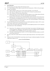
... Circuit Block Diagram VCC ON / OFF Brightness control Regulator U.V.P. VDD Control IC : OZ960 Enable OSC SST Dimming control Output driver Protection Ignition Regulation Full-bridge switching Transformer Detection Feed back Lamp Page 4 AL1702 2. tion of feedback of the CCFL current from power source. 2.1 VCC: When On/Off pin of I101 to drive Q105 and perform a wide dimming control for I101 power supply. 2.2 Control IC: I101...
... Circuit Block Diagram VCC ON / OFF Brightness control Regulator U.V.P. VDD Control IC : OZ960 Enable OSC SST Dimming control Output driver Protection Ignition Regulation Full-bridge switching Transformer Detection Feed back Lamp Page 4 AL1702 2. tion of feedback of the CCFL current from power source. 2.1 VCC: When On/Off pin of I101 to drive Q105 and perform a wide dimming control for I101 power supply. 2.2 Control IC: I101...
AL1702 Service Guide
Page 7
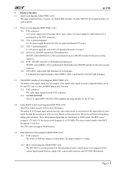
... VESA standard, also plug and play function. 3.3.1 P302 connector The video input signals from the 5V source. 3.2.4 Q303, I312 : ON/OFF control for LCD module power ON/OFF control (PANELVCC_EN) is performed for power ON/OFF and also for the power saving sequence. 3.2.5 R306 : ON/OFF control for LCD module back light power ON/OFF control (BKLT_EN) is performed for black light power ON/OFF and also for the power saving sequence. 3.2.6 Q301,Q302 : Adjust...
... VESA standard, also plug and play function. 3.3.1 P302 connector The video input signals from the 5V source. 3.2.4 Q303, I312 : ON/OFF control for LCD module power ON/OFF control (PANELVCC_EN) is performed for power ON/OFF and also for the power saving sequence. 3.2.5 R306 : ON/OFF control for LCD module back light power ON/OFF control (BKLT_EN) is performed for black light power ON/OFF and also for the power saving sequence. 3.2.6 Q301,Q302 : Adjust...
AL1702 Service Guide
Page 8
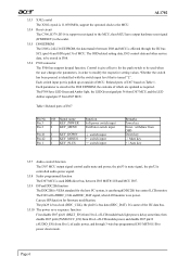
..., then MCU have LEDGreen and Amber light, the LEDGreen signal pin 36 from I307 MCU, and the LED Amber signal pin 37 from I307 MCU. It is turned "L". The OSD related setting data, I305 control data and other service data, to be used DDR direct bus, between I308 and MCU is effected through 3-wire bus programmed I305 MST8111B to power down mode.
..., then MCU have LEDGreen and Amber light, the LEDGreen signal pin 36 from I307 MCU, and the LED Amber signal pin 37 from I307 MCU. It is turned "L". The OSD related setting data, I305 control data and other service data, to be used DDR direct bus, between I308 and MCU is effected through 3-wire bus programmed I305 MST8111B to power down mode.
AL1702 Service Guide
Page 9
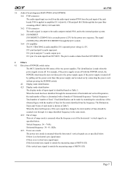
... the POWER switch, the POWER switch must be made when the power supply is turn on Table 2. If there is no horizontal sync signal input. The identification is made by connecting the power cord, without pressing the POWER switch. 4.2 Display mode identification 4.2.1 Display mode identification The display mode of input signal is identified based on when active the power supply again. Vertical frequency : 56 ~ 76 Hz. I311 pin14 and pin17 is audio input port. When the mode has been identified through the Q311 control...
... the POWER switch, the POWER switch must be made when the power supply is turn on Table 2. If there is no horizontal sync signal input. The identification is made by connecting the power cord, without pressing the POWER switch. 4.2 Display mode identification 4.2.1 Display mode identification The display mode of input signal is identified based on when active the power supply again. Vertical frequency : 56 ~ 76 Hz. I311 pin14 and pin17 is audio input port. When the mode has been identified through the Q311 control...
AL1702W Service Guide
Page 4
... radiate radio frequency energy, and if not installed and used in this product meets the ENERGY STAR® guidelines for compliance could void the user's authority to Part 15 of this printed Service Guide. Shielded interface cables and AC power cord, if any radio or TV interference caused by turning the equipment off and on, the user is made, it supports, please read...
... radiate radio frequency energy, and if not installed and used in this product meets the ENERGY STAR® guidelines for compliance could void the user's authority to Part 15 of this printed Service Guide. Shielded interface cables and AC power cord, if any radio or TV interference caused by turning the equipment off and on, the user is made, it supports, please read...
AL1702W Service Guide
Page 5
... or local power company. z Due to service the monitor yourself; Never spill liquids on a wall or shelf, uses a mounting kit approved by changing the image or turning off the Power Switch and then turn it will protect the monitor from overheating, be sure these openings are normal with UL listed computers which have an electrician install the correct outlet, or use . In this case, the screen is...
... or local power company. z Due to service the monitor yourself; Never spill liquids on a wall or shelf, uses a mounting kit approved by changing the image or turning off the Power Switch and then turn it will protect the monitor from overheating, be sure these openings are normal with UL listed computers which have an electrician install the correct outlet, or use . In this case, the screen is...
AL1702W Service Guide
Page 6
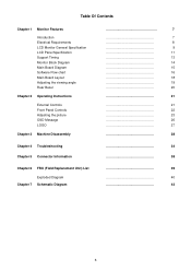
... Of Contents Chapter 1 Monitor Features Introduction Electrical Requirements LCD Monitor General Specification LCD Panel Specification Support Timing Monitor Block Diagram Main Board Diagram Software Flow chart Main Board Layout Adjusting the viewing angle Rear Bezel Chapter 2 Operating Instructions External Controls Front Panel Controls Adjusting the picture OSD Message LOGO Chapter 3 Machine Disassembly Chapter 4 Troubleshooting Chapter 5 Connector Information Chapter 6 FRU (Field Replacement Unit) List Exploded Diagram Chapter 7 Schematic Diagram 7 7 8 9 11 13...
... Of Contents Chapter 1 Monitor Features Introduction Electrical Requirements LCD Monitor General Specification LCD Panel Specification Support Timing Monitor Block Diagram Main Board Diagram Software Flow chart Main Board Layout Adjusting the viewing angle Rear Bezel Chapter 2 Operating Instructions External Controls Front Panel Controls Adjusting the picture OSD Message LOGO Chapter 3 Machine Disassembly Chapter 4 Troubleshooting Chapter 5 Connector Information Chapter 6 FRU (Field Replacement Unit) List Exploded Diagram Chapter 7 Schematic Diagram 7 7 8 9 11 13...
AL1702W Service Guide
Page 7
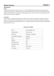
... stereo audio amplifier with no radiation. Monitor Features Chapter 1 Introduction Scope This specification defines the requirements for the 17" MICROPROCESSOR based Multi-mode supported high resolution color LCD monitor. This will alleviate the growing health concerns. Description The LCD monitor is designed with the latest LCD technology to provide a performance oriented product with OSD control to general 15-pin D-sub VGA connector, also supports VESA DPMS power management and plug & play...
... stereo audio amplifier with no radiation. Monitor Features Chapter 1 Introduction Scope This specification defines the requirements for the 17" MICROPROCESSOR based Multi-mode supported high resolution color LCD monitor. This will alleviate the growing health concerns. Description The LCD monitor is designed with the latest LCD technology to provide a performance oriented product with OSD control to general 15-pin D-sub VGA connector, also supports VESA DPMS power management and plug & play...

AL1702W Service Guide
Page 8
...) = Ft-L x 3.426 lux = foot-candle x 10.76 8 Ambient light Viewing distance Warm up time All specifications Measuring equipment Control settings User brightness control User contrast control User red/white balance, Green/white balance and Blue/white balance control Power input Ambient temperature Display mode : Dark room : 40 cm for LCD performance, 20 cm for LCD failures : >30 minutes : Chroma 7120 signal generator or equivalent, directly Connected to factory preset value, which allows that the brightest two of...
...) = Ft-L x 3.426 lux = foot-candle x 10.76 8 Ambient light Viewing distance Warm up time All specifications Measuring equipment Control settings User brightness control User contrast control User red/white balance, Green/white balance and Blue/white balance control Power input Ambient temperature Display mode : Dark room : 40 cm for LCD performance, 20 cm for LCD failures : >30 minutes : Chroma 7120 signal generator or equivalent, directly Connected to factory preset value, which allows that the brightest two of...
AL1702W Service Guide
Page 17
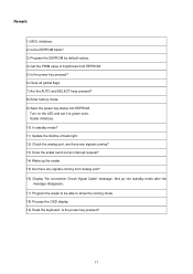
... mode? 11) Update the lifetime of brightness from analog port? 16) Display "No connection Check Signal Cable" message. Turn on the LED and set it to show the coming from EEPROM. 5) Is the power key pressed? 6) Clear all global flags. 7) Are the AUTO and SELECT keys pressed? 8) Enter factory mode. 9) Save the power key status into standby mode after the message disappears. 17) Program the scalar to be able to green color...
... mode? 11) Update the lifetime of brightness from analog port? 16) Display "No connection Check Signal Cable" message. Turn on the LED and set it to show the coming from EEPROM. 5) Is the power key pressed? 6) Clear all global flags. 7) Are the AUTO and SELECT keys pressed? 8) Enter factory mode. 9) Save the power key status into standby mode after the message disappears. 17) Program the scalar to be able to green color...
AL1702W Service Guide
Page 21
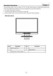
... front panel of the monitor. Description Auto Config / Exit < Power Button / Power Indicator Item 4. 5. External Controls Item 1. 2. 3. Operating Instructions Chapter 2 Press the power button to turn the monitor on the monitor position. The power indicator will light up. By changing these settings, the picture can be adjusted to your personal preferences. • The power cord should be connected. • Connect the video cable from the monitor to the video card. • Press the power button to turn on or off. Description > MENU/ENTER...
... front panel of the monitor. Description Auto Config / Exit < Power Button / Power Indicator Item 4. 5. External Controls Item 1. 2. 3. Operating Instructions Chapter 2 Press the power button to turn the monitor on the monitor position. The power indicator will light up. By changing these settings, the picture can be adjusted to your personal preferences. • The power cord should be connected. • Connect the video cable from the monitor to the video card. • Press the power button to turn on or off. Description > MENU/ENTER...
AL1702W Service Guide
Page 27
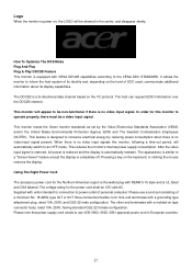
... the display. Using The Right Power Cord The accessory power cord for this monitor, following a time-out period, will automatically switch to conserve electrical energy by the Video Electronics Standards Association (VESA) and/or the United States Environmental Protection Agency (EPA) and The Swedish Confederation Employees (NUTEK). Please note that power supply cord needs to use a cord set by reducing power consumption when there is no video input signals this monitor to a "Screen...
... the display. Using The Right Power Cord The accessory power cord for this monitor, following a time-out period, will automatically switch to conserve electrical energy by the Video Electronics Standards Association (VESA) and/or the United States Environmental Protection Agency (EPA) and The Swedish Confederation Employees (NUTEK). Please note that power supply cord needs to use a cord set by reducing power consumption when there is no video input signals this monitor to a "Screen...

AL1702W User's Guide
Page 1
... YOUR SAFETY 1 SAFETY PRECAUTIONS 2 SPECIAL NOTES ON LCD MONITORS 3 BEFORE YOU OPERATE THE MONITOR 3 FEATURES 3 PACKING LIST 3 INSTALLATION INSTRUCTIONS 4 CONTROLS AND CONNECTORS 5 ADJUSTING THE VIEWING ANGLE 6 OPERATING INSTRUCTIONS 7 GENERAL INSTRUCTIONS 7 HOW TO ADJUST A SETTING 9 ADJUSTING THE PICTURE 10-11 PLUG AND PLAY 12 TECHNICAL SUPPORT(FAQ 13-14 ERROR MESSAGE & POSSIBLE SOLUTION --------- 15 APPENDIX 16 SPECIFICATIONS 16-17 FACTORY PRESET TIMING TABLE 18 CONNECTOR PIN ASSIGNMENT 19 For more information and...
... YOUR SAFETY 1 SAFETY PRECAUTIONS 2 SPECIAL NOTES ON LCD MONITORS 3 BEFORE YOU OPERATE THE MONITOR 3 FEATURES 3 PACKING LIST 3 INSTALLATION INSTRUCTIONS 4 CONTROLS AND CONNECTORS 5 ADJUSTING THE VIEWING ANGLE 6 OPERATING INSTRUCTIONS 7 GENERAL INSTRUCTIONS 7 HOW TO ADJUST A SETTING 9 ADJUSTING THE PICTURE 10-11 PLUG AND PLAY 12 TECHNICAL SUPPORT(FAQ 13-14 ERROR MESSAGE & POSSIBLE SOLUTION --------- 15 APPENDIX 16 SPECIFICATIONS 16-17 FACTORY PRESET TIMING TABLE 18 CONNECTOR PIN ASSIGNMENT 19 For more information and...

AL1702W User's Guide
Page 3
... similar surface. opening or removing covers can injure a person and cause serious damage to protect it from the type of power source indicated on a wall or shelf, use a mounting kit approved by the manufacturer and follow the kit instructions. z To ensure satisfactory operation, use the monitor only with a third (grounding) pin. If the monitor falls, it will not be installed near or over...
... similar surface. opening or removing covers can injure a person and cause serious damage to protect it from the type of power source indicated on a wall or shelf, use a mounting kit approved by the manufacturer and follow the kit instructions. z To ensure satisfactory operation, use the monitor only with a third (grounding) pin. If the monitor falls, it will not be installed near or over...
AL1702W User's Guide
Page 4
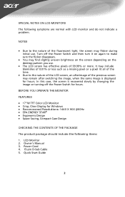
... YOU OPERATE THE MONITOR FEATURES • 17"W TFT Color LCD Monitor • Crisp, Clear Display for hours. SPECIAL NOTES ON LCD MONITORS The following items: 1. Power Cord 4. 15-pin D-Sub Cable 5 . Turn off the Power Switch for hours. LCD Monitor 2. Quick Start Guide 3 In this case, the screen is displayed for Windows • Recommened Resolutions: 1440 X 900 @60Hz • EPA ENERGY STAR® • Ergonomic Design • Space Saving, Compact Case Design CHECKING THE CONTENTS...
... YOU OPERATE THE MONITOR FEATURES • 17"W TFT Color LCD Monitor • Crisp, Clear Display for hours. SPECIAL NOTES ON LCD MONITORS The following items: 1. Power Cord 4. 15-pin D-Sub Cable 5 . Turn off the Power Switch for hours. LCD Monitor 2. Quick Start Guide 3 In this case, the screen is displayed for Windows • Recommened Resolutions: 1440 X 900 @60Hz • EPA ENERGY STAR® • Ergonomic Design • Space Saving, Compact Case Design CHECKING THE CONTENTS...
AL1702W User's Guide
Page 5
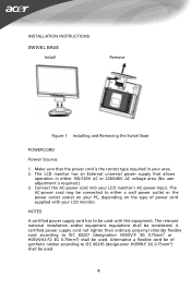
... user adjustment is the correct type required in either a wall power outlet or the power outlet socket on your PC, depending on the type of synthetic rubber according to be used . 4 Make sure that allows operation in your area. 2. Alternative a flexible cord be considered. INSTALLATION INSTRUCTIONS SWIVEL BASE IVEL BASE Install Remove Figure 1 Installing and Removing the Swivel Base POWERCORD Power Source: 1. This LCD monitor has an External universal power supply that the power cord...
... user adjustment is the correct type required in either a wall power outlet or the power outlet socket on your PC, depending on the type of synthetic rubber according to be used . 4 Make sure that allows operation in your area. 2. Alternative a flexible cord be considered. INSTALLATION INSTRUCTIONS SWIVEL BASE IVEL BASE Install Remove Figure 1 Installing and Removing the Swivel Base POWERCORD Power Source: 1. This LCD monitor has an External universal power supply that the power cord...
AL1702W User's Guide
Page 9
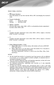
... factory. • To keep the monitor looking new, periodically clean it . 8 Orange - NOTES • Do not install the monitor in a location near heat sources such as radiators or air ducts, or in handy if you ever have to activate the Auto Adjustment function. FRONT PANEL CONTROL • /Power Button: Press this button to set the HPos, VPos, Clock and Focus. Power On mode. Stand by mode. • MENU / ENTER : Activate OSD menu...
... factory. • To keep the monitor looking new, periodically clean it . 8 Orange - NOTES • Do not install the monitor in a location near heat sources such as radiators or air ducts, or in handy if you ever have to activate the Auto Adjustment function. FRONT PANEL CONTROL • /Power Button: Press this button to set the HPos, VPos, Clock and Focus. Power On mode. Stand by mode. • MENU / ENTER : Activate OSD menu...
AL1702W User's Guide
Page 12
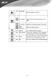
N/A DDC/CI Turn ON/OFF DDC/CI support. H. V. N/A Exit Save user adjustment and OSD disappear. 11 Position Adjust the horizontal position of the OSD. Position Adjust the vertical position of the OSD. N/A Information Show the resolution, H/V frequency and input port of Auto-configuration and set the color temperature to Cool. OSD Timeout Adjust the OSD timeout. N/A Reset Clear each old status of current iput timing. N/A Language Multi-language selection.
N/A DDC/CI Turn ON/OFF DDC/CI support. H. V. N/A Exit Save user adjustment and OSD disappear. 11 Position Adjust the horizontal position of the OSD. Position Adjust the vertical position of the OSD. N/A Information Show the resolution, H/V frequency and input port of Auto-configuration and set the color temperature to Cool. OSD Timeout Adjust the OSD timeout. N/A Reset Clear each old status of current iput timing. N/A Language Multi-language selection.
AL1702W User's Guide
Page 13
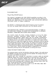
... THERE IS NO VIDEO INPUT SIGNAL. The voltage rating for connection to use a cord set by reducing power consumption when there is a bidirectional data channel based on the keyboard, or clicking the mouse. PLUG AND PLAY Plug & Play DDC2B Feature This monitor is completely off. The appearance is similar to a "Screen Saver" feature except the display is equipped with a grounding type attachment plug, rated 10A, 250V, CEE...
... THERE IS NO VIDEO INPUT SIGNAL. The voltage rating for connection to use a cord set by reducing power consumption when there is a bidirectional data channel based on the keyboard, or clicking the mouse. PLUG AND PLAY Plug & Play DDC2B Feature This monitor is completely off. The appearance is similar to a "Screen Saver" feature except the display is equipped with a grounding type attachment plug, rated 10A, 250V, CEE...
AL1702W User's Guide
Page 14
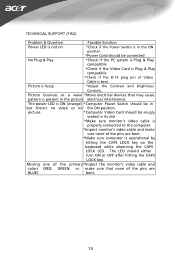
... position. Missing one of the primary *Inspect the monitor's video cable and colors (RED, GREEN, or make sure none of the pins are BLUE) bent. 13 Picture bounces or a wave *Move electrical devices that none of Video Cable is bent Picture is fuzzy *Adjust the Contrast and Brightness Controls. The LED should be connected No Plug & Play *Check if the PC system is Plug & Play compatible *Check if the Video Card is Plug & Play compatible *Check if the D-15 plug...
... position. Missing one of the primary *Inspect the monitor's video cable and colors (RED, GREEN, or make sure none of the pins are BLUE) bent. 13 Picture bounces or a wave *Move electrical devices that none of Video Cable is bent Picture is fuzzy *Adjust the Contrast and Brightness Controls. The LED should be connected No Plug & Play *Check if the PC system is Plug & Play compatible *Check if the Video Card is Plug & Play compatible *Check if the D-15 plug...


