
AL1702 Service Guide
Page 9
...Table 2. The identification is made by connecting the power cord, without pressing the POWER switch. 4.2 Display mode identification 4.2.1 Display mode identification The display mode of input signal is identified based on when active the power supply again. Final identification can be turn off with .... Vertical frequency : 56 ~ 76 Hz. If the horizontal sync signal is outside the measuring range of MST8111B. AL1702 3.6 Audio (Circuit diagrams MAIN PWB 8 of 8) [OPTION] 3.6.1 P309 connector The audio signal input received from the audio input terminal P309 from the jack input ...
...Table 2. The identification is made by connecting the power cord, without pressing the POWER switch. 4.2 Display mode identification 4.2.1 Display mode identification The display mode of input signal is identified based on when active the power supply again. Final identification can be turn off with .... Vertical frequency : 56 ~ 76 Hz. If the horizontal sync signal is outside the measuring range of MST8111B. AL1702 3.6 Audio (Circuit diagrams MAIN PWB 8 of 8) [OPTION] 3.6.1 P309 connector The audio signal input received from the audio input terminal P309 from the jack input ...

AL1702 Service Guide
Page 13
NG OK Input the sync signal of LED is connected normally. Proceed "checking the resolution change the cable. Page 11 it is indicated with "OUT OIF RANGE" at the Yes time of the frequency that it is indicated with "VIDEO INPUT". Proceed "No OSM display" section. No When a sugnal isn't being inputed, it can't be distinguished. 1. No display of screen (Screen is black, color of computer, or change IC movement" section. Check if the sync signal from computer is output and if the video cable is amber) AL1702 Does OSM display when you push PROCEED buttom.
NG OK Input the sync signal of LED is connected normally. Proceed "checking the resolution change the cable. Page 11 it is indicated with "OUT OIF RANGE" at the Yes time of the frequency that it is indicated with "VIDEO INPUT". Proceed "No OSM display" section. No When a sugnal isn't being inputed, it can't be distinguished. 1. No display of screen (Screen is black, color of computer, or change IC movement" section. Check if the sync signal from computer is output and if the video cable is amber) AL1702 Does OSM display when you push PROCEED buttom.

AL1702 Service Guide
Page 14
... "PROCEED" key. Check OSM menu is connected between the MAIN PWB and LCD module. NG OK Proceed "Abnormal sreen" dection" Check if the LCD video signal cable is display on the host. 2)Rsconnect the video cable. 3)Change the video cable. NG OK Check the video cable for output... signal with all black only. 1)Change pattern of LED is disconnected. Check the host for failure. NG OK Failure Point The cable is green) AL1702 Is backlight lit? NG OK Refer "Checking...
... "PROCEED" key. Check OSM menu is connected between the MAIN PWB and LCD module. NG OK Proceed "Abnormal sreen" dection" Check if the LCD video signal cable is display on the host. 2)Rsconnect the video cable. 3)Change the video cable. NG OK Check the video cable for output... signal with all black only. 1)Change pattern of LED is disconnected. Check the host for failure. NG OK Failure Point The cable is green) AL1702 Is backlight lit? NG OK Refer "Checking...

AL1702W Service Guide
Page 8
... User red/white balance, Green/white balance and Blue/white balance control Power input Ambient temperature Display mode : Dark room : 40 cm for LCD performance, 20 cm for LCD failures : >30 minutes : Chroma 7120 signal generator or equivalent, directly Connected to factory preset value, which allows that the brightest two of...
... User red/white balance, Green/white balance and Blue/white balance control Power input Ambient temperature Display mode : Dark room : 40 cm for LCD performance, 20 cm for LCD failures : >30 minutes : Chroma 7120 signal generator or equivalent, directly Connected to factory preset value, which allows that the brightest two of...
AL1702W Service Guide
Page 17
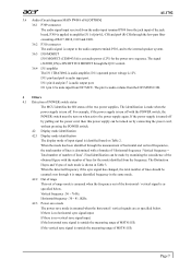
...the scalar to be able to green color. Scalar initializes. 10) In standby mode? 11) Update the lifetime of brightness from analog port? 16) Display "No connection Check Signal Cable" message. And go into EEPROM. Remark: 1) MCU initializes. 2) Is the EEPROM blank? 3) Program the EEPROM by default values. 4) Get... PWM value of back light. 12) Check the analog port, are there any signals coming? 13) Does the scalar send out an interrupt request? 14) Wake up the scalar. 15) Are there any signals coming mode. 18) Process the OSD display. 19) Read the keyboard. Is the power key pressed? 17
...the scalar to be able to green color. Scalar initializes. 10) In standby mode? 11) Update the lifetime of brightness from analog port? 16) Display "No connection Check Signal Cable" message. And go into EEPROM. Remark: 1) MCU initializes. 2) Is the EEPROM blank? 3) Program the EEPROM by default values. 4) Get... PWM value of back light. 12) Check the analog port, are there any signals coming? 13) Does the scalar send out an interrupt request? 14) Wake up the scalar. 15) Are there any signals coming mode. 18) Process the OSD display. 19) Read the keyboard. Is the power key pressed? 17
AL1702W Service Guide
Page 27
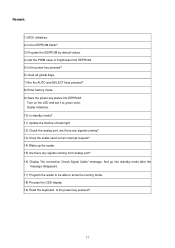
...monitor to operate properly, there must be a video input signal. This feature is designed to be non-functional if there is no video-input signal present. After the video input signal is restored, full power is restored and the display is completely off. The DDC2B is a bi-directional data... channel based on the keyboard, or clicking the mouse restores the display. This monitor will appear to conserve...
...monitor to operate properly, there must be a video input signal. This feature is designed to be non-functional if there is no video-input signal present. After the video input signal is restored, full power is restored and the display is completely off. The DDC2B is a bi-directional data... channel based on the keyboard, or clicking the mouse restores the display. This monitor will appear to conserve...
AL1702W User's Guide
Page 13
... POWER CORD : The accessory power cord for the power cord shall be 125 volts AC. The display is restored by reducing power consumption when there is no video input signal this monitor, following a time-out period, will automatically switch to a "Screen Saver" feature except... the display is automatically redrawn. When there is no video-input signal present. After the video input signal is restored, full power is restored and the display is completely off. The other end terminates with units intended for connection...
... POWER CORD : The accessory power cord for the power cord shall be 125 volts AC. The display is restored by reducing power consumption when there is no video input signal this monitor, following a time-out period, will automatically switch to a "Screen Saver" feature except... the display is automatically redrawn. When there is no video-input signal present. After the video input signal is restored, full power is restored and the display is completely off. The other end terminates with units intended for connection...

AL1702W User's Guide
Page 16
INPUT NOT SUPPORT : Your computer has been set to unsuitable display mode, set the computer to display mode given in the following table (See page 18). 15 Check the signal -cable connection pins for damage. Check that the signal-cable is properly connected, If the connector is loose, tighten the connector's screws. 2. ERROR MESSAGE & POSSIBLE SOLUTION CABLE NOT CONNECTED : 1.
INPUT NOT SUPPORT : Your computer has been set to unsuitable display mode, set the computer to display mode given in the following table (See page 18). 15 Check the signal -cable connection pins for damage. Check that the signal-cable is properly connected, If the connector is loose, tighten the connector's screws. 2. ERROR MESSAGE & POSSIBLE SOLUTION CABLE NOT CONNECTED : 1.
AL1702W User's Guide
Page 17
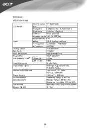
...Viewable angle 140° (H) 130° (V) Response time 8 ms Input Video R,G,B Analog Interface H-Frequency 55.469kHz - 70.635kHz V-Frequency 60-75Hz Display Colors 262144 Colors Dot Clock 170MHz Max. Resolution Plug & Play EPA ENERGY STAR® ON Mode 1440 × 900 @75Hz VESA DDC2BTM ≤... 37W OFF Mode ≤ 1W Input Connector D-Sub 15pin Input Video Signal Analog:0.7Vp-p(standard), 75 OHM, Positive Maximum Screen Size Horizontal : 367.2mm Vertical : 229.5mm Power Source 100-240V~, 50/60Hz Environmental...
...Viewable angle 140° (H) 130° (V) Response time 8 ms Input Video R,G,B Analog Interface H-Frequency 55.469kHz - 70.635kHz V-Frequency 60-75Hz Display Colors 262144 Colors Dot Clock 170MHz Max. Resolution Plug & Play EPA ENERGY STAR® ON Mode 1440 × 900 @75Hz VESA DDC2BTM ≤... 37W OFF Mode ≤ 1W Input Connector D-Sub 15pin Input Video Signal Analog:0.7Vp-p(standard), 75 OHM, Positive Maximum Screen Size Horizontal : 367.2mm Vertical : 229.5mm Power Source 100-240V~, 50/60Hz Environmental...

AL1702W User's Guide
Page 20
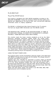
Pin Color Display Signal Cable DESCRIPTION Red Green Blue Monitor Ground DDC-return R-Ground G-Ground B-Ground PIN NO. 9. 10. 11. 12. 13. 14. 15. DESCRIPTION +5V Logic Ground Monitor Ground DDC-Serial Data H-Sync V-Sync DDC-Serial Clock 19 CONNECTOR PIN ASSIGNMENT 1 5 6 10 11 15 PIN NO. 1. 2. 3. 4. 5. 6. 7. 8. 15 -
Pin Color Display Signal Cable DESCRIPTION Red Green Blue Monitor Ground DDC-return R-Ground G-Ground B-Ground PIN NO. 9. 10. 11. 12. 13. 14. 15. DESCRIPTION +5V Logic Ground Monitor Ground DDC-Serial Data H-Sync V-Sync DDC-Serial Clock 19 CONNECTOR PIN ASSIGNMENT 1 5 6 10 11 15 PIN NO. 1. 2. 3. 4. 5. 6. 7. 8. 15 -


