User Manual
Page 9
...-installation instructions 27 Post-installation instructions 27 Opening the server 28 Removing and installing the side panel 28 Configuring the hard disk drive 30 Accessing the drive bays 30 Hard disk drive configuration guidelines 31 Determining the drive status 32 Configuring a 5.25-inch storage device 38 Installing an optional 5.25-inch storage device 38 Removing a 5.25-inch storage device 41 Replacing the processor and heatsink fan assembly 42 Removing and installing the heatsink fan assembly 42 Removing and installing the processor 47 Upgrading the system memory...
...-installation instructions 27 Post-installation instructions 27 Opening the server 28 Removing and installing the side panel 28 Configuring the hard disk drive 30 Accessing the drive bays 30 Hard disk drive configuration guidelines 31 Determining the drive status 32 Configuring a 5.25-inch storage device 38 Installing an optional 5.25-inch storage device 38 Removing a 5.25-inch storage device 41 Replacing the processor and heatsink fan assembly 42 Removing and installing the heatsink fan assembly 42 Removing and installing the processor 47 Upgrading the system memory...
User Manual
Page 10
...menu Advanced menu Processor Configuration ATA Controller Configuration Serial Port Configuration USB Configuration USB Mass Storage Device Configuration PCI/PnP Configuration Advanced Chipset Control Power Configuration Security Settings Server Management System Information Console Redirection Boot Configuration Boot Setting Configuration Boot Device Priority Hard Disk Drives Removable Drives CD/DVD Drives Network Drives Exit Options 5 System troubleshooting Resetting the system Initial system startup problems BIOS error beep codes Initial troubleshooting checklist Hardware diagnostic testing...
...menu Advanced menu Processor Configuration ATA Controller Configuration Serial Port Configuration USB Configuration USB Mass Storage Device Configuration PCI/PnP Configuration Advanced Chipset Control Power Configuration Security Settings Server Management System Information Console Redirection Boot Configuration Boot Setting Configuration Boot Device Priority Hard Disk Drives Removable Drives CD/DVD Drives Network Drives Exit Options 5 System troubleshooting Resetting the system Initial system startup problems BIOS error beep codes Initial troubleshooting checklist Hardware diagnostic testing...
User Manual
Page 11
... SATA RAID Creation Adaptec Onboard SATA RAID Creation MegaRAID SAS 8204ELP Creation MegaRAID SAS 8708EM2 RAID Creation Flex IO SAS RAID Creation 113 114 115 115 116 118 120 122 Appendix B Rack mount configuration Rack installation information System rack installation Vertical mounting hole pattern Installing the system into the rack 125 126 128 129 130 Appendix C Acer Smart Console Using Acer Smart Console Software requirements Accessing Acer Smart Console Acer Smart Console user interface System Information Server Health Configuration Remote Control Launch SOL Virtual Media Maintenance...
... SATA RAID Creation Adaptec Onboard SATA RAID Creation MegaRAID SAS 8204ELP Creation MegaRAID SAS 8708EM2 RAID Creation Flex IO SAS RAID Creation 113 114 115 115 116 118 120 122 Appendix B Rack mount configuration Rack installation information System rack installation Vertical mounting hole pattern Installing the system into the rack 125 126 128 129 130 Appendix C Acer Smart Console Using Acer Smart Console Software requirements Accessing Acer Smart Console Acer Smart Console user interface System Information Server Health Configuration Remote Control Launch SOL Virtual Media Maintenance...
User Manual
Page 24
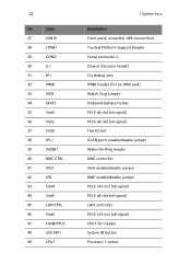
... CPU1 1 System tour Description Front panel accessible USB connections Trusted Platform Support Header Serial connector 2 Chassis intrusion header For debug only IPMB header (for an IPMI card) Watch Dog jumper Onboard battery holder PCI-E x8 slot (x4 signal) PCI-E x8 slot (x4 signal) Flex IO slot GLAN ports enable/disable jumper Wake-On-Ring header BMC controller VGA enable/disable jumper BMC enable/disable jumper PCI-E x16 slot (x8 signal) PCI-E x8 slot (x4 signal) LAN controller PCI-E x16 slot (x8 signal) CPU1 fan header System ID button Processor 1 socket
... CPU1 1 System tour Description Front panel accessible USB connections Trusted Platform Support Header Serial connector 2 Chassis intrusion header For debug only IPMB header (for an IPMI card) Watch Dog jumper Onboard battery holder PCI-E x8 slot (x4 signal) PCI-E x8 slot (x4 signal) Flex IO slot GLAN ports enable/disable jumper Wake-On-Ring header BMC controller VGA enable/disable jumper BMC enable/disable jumper PCI-E x16 slot (x8 signal) PCI-E x8 slot (x4 signal) LAN controller PCI-E x16 slot (x8 signal) CPU1 fan header System ID button Processor 1 socket
User Manual
Page 91
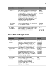
... 32-bit IDE data transfer. Auto, Disabled, Enabled, Select Enable to confi gure the onboard COM 2 port as a virtual COM port for the interrupt address. When this feature to set to prevent the AMI BIOS from accessing system resources. Select Disabled to Disabled, the serial port will become physically unavailable. Select 3F8/ IRQ4 to allow the serial port to automatically detect hard disk drive support. Select Auto to allow the AMI BIOS to configure the...
... 32-bit IDE data transfer. Auto, Disabled, Enabled, Select Enable to confi gure the onboard COM 2 port as a virtual COM port for the interrupt address. When this feature to set to prevent the AMI BIOS from accessing system resources. Select Disabled to Disabled, the serial port will become physically unavailable. Select 3F8/ IRQ4 to allow the serial port to automatically detect hard disk drive support. Select Auto to allow the AMI BIOS to configure the...
User Manual
Page 92
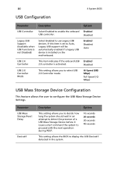
... Enabled to use Legacy USB devices. Enabled Disabled Legacy USB Support (Available when USB Functions is not Disabled) Select Enabled to enable the onboard USB controller. Enabled Disabled USB 2.0 Controller Mode This setting allows you to decide how long the system should wait in the system. Hi-Speed (480 Mbps) Full Speed (12 Mbps) USB Mass Storage Device Configuration This feature allows the user to display the USB Device#1 detected in an attempt to detect the presence of a USB Mass Storage Device before it issues a start command...
... Enabled to use Legacy USB devices. Enabled Disabled Legacy USB Support (Available when USB Functions is not Disabled) Select Enabled to enable the onboard USB controller. Enabled Disabled USB 2.0 Controller Mode This setting allows you to decide how long the system should wait in the system. Hi-Speed (480 Mbps) Full Speed (12 Mbps) USB Mass Storage Device Configuration This feature allows the user to display the USB Device#1 detected in an attempt to detect the presence of a USB Mass Storage Device before it issues a start command...
User Manual
Page 104
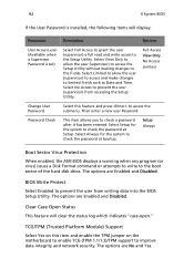
... Password is installed, the following items will clear the status log which indicates "case-open." TCG/TPM (Trusted Platform Module) Support Select Yes on the motherboard to enable TCG (TPM 1.1/1.2)/TPM support to check the password at bootup. Select Limited to allow the user (supervisor) to access the Setup Utility without making changes to the boot sector of the hard disk drive. Full Access View Only No Access Limited Change User Password Select this item and enable the TPM jumper...
... Password is installed, the following items will clear the status log which indicates "case-open." TCG/TPM (Trusted Platform Module) Support Select Yes on the motherboard to enable TCG (TPM 1.1/1.2)/TPM support to check the password at bootup. Select Limited to allow the user (supervisor) to access the Setup Utility without making changes to the boot sector of the hard disk drive. Full Access View Only No Access Limited Change User Password Select this item and enable the TPM jumper...
User Manual
Page 116
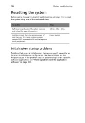
... troubleshooting, attempt first to all peripherals. This clears system memory, restarts POST, reloads the OS and halts power to reset the system using one of the methods below. To do this Press Soft boot reset to clear the system memory and reload the operating system. ++ Cold boot reset. Turn the system power off and then on page 111. Hardware failure is problem with the application software" on . Power button Initial system startup problems Problems...
... troubleshooting, attempt first to all peripherals. This clears system memory, restarts POST, reloads the OS and halts power to reset the system using one of the methods below. To do this Press Soft boot reset to clear the system memory and reload the operating system. ++ Cold boot reset. Turn the system power off and then on page 111. Hardware failure is problem with the application software" on . Power button Initial system startup problems Problems...
User Manual
Page 118
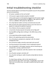
... slots? • Are all system jumpers correctly set? • Are all switch settings on add-in the BIOS setup utility correct? • Is the operating system properly loaded? • Refer to the manufacturer's documentation that there are encountering. • AC power available at the wall outlet? • Is the power supply module properly installed? • Is the system power cord properly plugged into the power supply module socket? 106 5 System troubleshooting...
... slots? • Are all system jumpers correctly set? • Are all switch settings on add-in the BIOS setup utility correct? • Is the operating system properly loaded? • Refer to the manufacturer's documentation that there are encountering. • AC power available at the wall outlet? • Is the power supply module properly installed? • Is the system power cord properly plugged into the power supply module socket? 106 5 System troubleshooting...
User Manual
Page 123
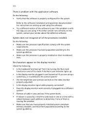
If you are using . Refer to the software installation and operation documentation for the system. If the other version runs correctly on the display monitor. Check the following : • Verify that there populated according to determine if one of the processors installed. 111 There is successful, install the cards back in and turned on their mainboard slots. System does not recognize all add-in cares and see if...
If you are using . Refer to the software installation and operation documentation for the system. If the other version runs correctly on the display monitor. Check the following : • Verify that there populated according to determine if one of the processors installed. 111 There is successful, install the cards back in and turned on their mainboard slots. System does not recognize all add-in cares and see if...
User Manual
Page 127
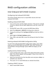
... see the RAID BIOS during POST. The current adapter settings appear. Loading Factory Default Setting 1 In the Configuration menu, select third option Reset Disks to create RAID volume with Intel onboard SATA RAID. RAID. Enabling onboard SATA RAID 1 Turn on selected hard disks. Creating a RAID 5 Volume 1 Select Create RAID Volume. 115 RAID configuration utilities Intel Onboard SATA RAID Creation Configuring Intel onboard SATA RAID This section briefly shows how to Non- Please click on Next to change the setting. 2 Select the hard disk drive that should...
... see the RAID BIOS during POST. The current adapter settings appear. Loading Factory Default Setting 1 In the Configuration menu, select third option Reset Disks to create RAID volume with Intel onboard SATA RAID. RAID. Enabling onboard SATA RAID 1 Turn on selected hard disks. Creating a RAID 5 Volume 1 Select Create RAID Volume. 115 RAID configuration utilities Intel Onboard SATA RAID Creation Configuring Intel onboard SATA RAID This section briefly shows how to Non- Please click on Next to change the setting. 2 Select the hard disk drive that should...
User Manual
Page 128
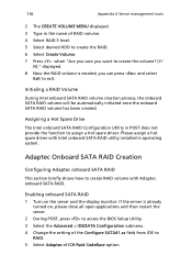
...? (Y/ N):" displayed. 8 Now the RAID volume is already turned on the server and the display monitor. 116 Appendix A Server management tools 2 The CREATE VOLUME MENU displayed. 3 Type in POST does not provide the function to assign a hot spare driver. Please assign a hot spare driver with Adaptec onboard SATA RAID. Enabling onboard SATA RAID 1 Turn on , please close all open applications and then restart the server. 2 During POST, press to access the BIOS Setup Utility. 3 Select the Advanced > IDE/SATA Configuration submenu. 4 Change the setting...
...? (Y/ N):" displayed. 8 Now the RAID volume is already turned on the server and the display monitor. 116 Appendix A Server management tools 2 The CREATE VOLUME MENU displayed. 3 Type in POST does not provide the function to assign a hot spare driver. Please assign a hot spare driver with Adaptec onboard SATA RAID. Enabling onboard SATA RAID 1 Turn on , please close all open applications and then restart the server. 2 During POST, press to access the BIOS Setup Utility. 3 Select the Advanced > IDE/SATA Configuration submenu. 4 Change the setting...
User Manual
Page 130
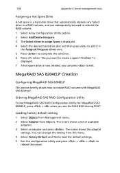
... default setting 1 Select Objects from Management menu. 2 Select Adapter from this menu. 4 Select Factory Default and Yes to load the default settings. 5 Exit the configuration utility and press + + to create RAID volume with MegaRAID SAS 8204ELP. MegaRAID SAS 8204ELP Creation Configuring MegaRAID SAS 8204ELP This section briefly shows how to reboot the server. You can change the setting from Objects. 118 Appendix A Server management tools Assigning a Hot Spare Drive A hot spare is a hard disk drive that automatically replaces any failed drive...
... default setting 1 Select Objects from Management menu. 2 Select Adapter from this menu. 4 Select Factory Default and Yes to load the default settings. 5 Exit the configuration utility and press + + to create RAID volume with MegaRAID SAS 8204ELP. MegaRAID SAS 8204ELP Creation Configuring MegaRAID SAS 8204ELP This section briefly shows how to reboot the server. You can change the setting from Objects. 118 Appendix A Server management tools Assigning a Hot Spare Drive A hot spare is a hard disk drive that automatically replaces any failed drive...

User Manual
Page 132
... the RAID BIOS during POST. MegaRAID SAS 8708EM2 RAID Creation Configuring MegaRAID SAS 8708EM2 This section briefly shows how to the Management Menu. The current adapter settings appear. Entering MegaRAID SAS RAID Configuration Utility To start to launch the configuration menu. 120 Appendix A Server management tools 5 Select Yes and the selected drive changes from No to Yes then click on Start to install the operating system. Click on Next to change the setting. 2 Change the setting of Set Factory Defaults from...
... the RAID BIOS during POST. MegaRAID SAS 8708EM2 RAID Creation Configuring MegaRAID SAS 8708EM2 This section briefly shows how to the Management Menu. The current adapter settings appear. Entering MegaRAID SAS RAID Configuration Utility To start to launch the configuration menu. 120 Appendix A Server management tools 5 Select Yes and the selected drive changes from No to Yes then click on Start to install the operating system. Click on Next to change the setting. 2 Change the setting of Set Factory Defaults from...
User Manual
Page 134
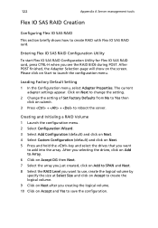
... reboot the server. Please click on Add to save the configuration. After POST finished, the Adapter Selection page will show on submit. 3 Press + + to launch the configuration menu. Entering Flex IO SAS RAID Configuration Utility To start Flex IO SAS RAID Configuration Utility for Flex IO SAS RAID card, press CTRL-H when you want to create RAID with Flex IO SAS RAID card. The current adapter settings appear. Click on Next to change the setting. 2 Change the setting of Set Factory Defaults...
... reboot the server. Please click on Add to save the configuration. After POST finished, the Adapter Selection page will show on submit. 3 Press + + to launch the configuration menu. Entering Flex IO SAS RAID Configuration Utility To start Flex IO SAS RAID Configuration Utility for Flex IO SAS RAID card, press CTRL-H when you want to create RAID with Flex IO SAS RAID card. The current adapter settings appear. Click on Next to change the setting. 2 Change the setting of Set Factory Defaults...
User Manual
Page 152
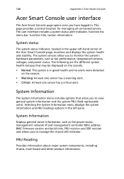
... readings options in . FRU Reading Provides information about major system components, including chassis, main board and other product information. The system sensors allow you to view general system information and the system FRU (field replaceable units). 140 Appendix C Acer Smart Console Acer Smart Console user interface The Acer Smart Console page opens once you to manage the chassis LED indicator. System Information Displays general server information, such as fan performance, temperature sensors, voltages, and power status.
... readings options in . FRU Reading Provides information about major system components, including chassis, main board and other product information. The system sensors allow you to view general system information and the system FRU (field replaceable units). 140 Appendix C Acer Smart Console Acer Smart Console user interface The Acer Smart Console page opens once you to manage the chassis LED indicator. System Information Displays general server information, such as fan performance, temperature sensors, voltages, and power status.
User Manual
Page 165
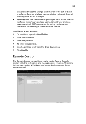
... configuration commands for disabling a communication channel. 153 that allows the user to change user access privileges. • Administrator: The administrator privilege has full access and can configure the software and add users. Operator privilege can not disable individual channels or change the behavior of the out-of-band interfaces. Administrator privilege have access to start a Remote Console session with the host system and manage power remotely. This menu include two options: KVM Remote Console Redirection and Server Power Control...
... configuration commands for disabling a communication channel. 153 that allows the user to change user access privileges. • Administrator: The administrator privilege has full access and can configure the software and add users. Operator privilege can not disable individual channels or change the behavior of the out-of-band interfaces. Administrator privilege have access to start a Remote Console session with the host system and manage power remotely. This menu include two options: KVM Remote Console Redirection and Server Power Control...
User Manual
Page 170
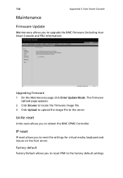
... to reset IPMI to reboot the BMC (IPMI) Controller. Upgrading firmware 1 On the Maintenance page click Enter Update Mode. The Firmware Upload page appears. 2 Click Browse to locate the firmware image file. 3 Click Upload to upload the image file to reset the settings for virtual media, keyboard and mouse on the host server. Factory default Factory Default allows you to the server. Unite reset Unite reset allows you to upgrade the BMC firmware (including Acer Smart Console...
... to reset IPMI to reboot the BMC (IPMI) Controller. Upgrading firmware 1 On the Maintenance page click Enter Update Mode. The Firmware Upload page appears. 2 Click Browse to locate the firmware image file. 3 Click Upload to upload the image file to reset the settings for virtual media, keyboard and mouse on the host server. Factory default Factory Default allows you to the server. Unite reset Unite reset allows you to upgrade the BMC firmware (including Acer Smart Console...
User Manual
Page 179
... ATA Controller Configuration 75 B BIOS CMOS RAM 66 configure 67 overview 66 BIOS Setup Advanced Chipset Control 82 Advanced menu 71 Advanced Processor Options 72 Boot Configuration 98 Boot Device Priority 99 Boot Setting Configuration 98 CD/DVD Drives 99 Hard Disk Drives 99 Network Drives 100 Retry Boot Devices 100 Removable Drives 99 enter Setup 67 Exit Options 101 Main menu 69 navigation keys 68 PCI/PnP Configuration 81 Power Configuration 89 Processor Configuration 72 167 Security Settings 91 Serial Port Configuration 79 Server Management 94 Console Redirection 96 Event Log Configuration...
... ATA Controller Configuration 75 B BIOS CMOS RAM 66 configure 67 overview 66 BIOS Setup Advanced Chipset Control 82 Advanced menu 71 Advanced Processor Options 72 Boot Configuration 98 Boot Device Priority 99 Boot Setting Configuration 98 CD/DVD Drives 99 Hard Disk Drives 99 Network Drives 100 Retry Boot Devices 100 Removable Drives 99 enter Setup 67 Exit Options 101 Main menu 69 navigation keys 68 PCI/PnP Configuration 81 Power Configuration 89 Processor Configuration 72 167 Security Settings 91 Serial Port Configuration 79 Server Management 94 Console Redirection 96 Event Log Configuration...
User Manual
Page 180
... supply module redundant bay 9 processor BIOS settings 72 configuration guidelines 47 installing 48 removing 47 replacing 47 PS/2 keyboard port 7 PS/2 mouse port 7 R rack installing 130 rack installation 125 mounting pattern 129 precautions 126 RAID configuration utilities 115 rear panel 7 removing 5.25 inch storage device 41 hard disk drive with carrier 33 heatsink fan assembly 42 processor 47 side panel 28 system memory 60 S safety CD or DVD viii serial port location 8 serial port configuration BIOS settings 79 server management tools 114 side panel installing 29 removing 28 Sparing mode...
... supply module redundant bay 9 processor BIOS settings 72 configuration guidelines 47 installing 48 removing 47 replacing 47 PS/2 keyboard port 7 PS/2 mouse port 7 R rack installing 130 rack installation 125 mounting pattern 129 precautions 126 RAID configuration utilities 115 rear panel 7 removing 5.25 inch storage device 41 hard disk drive with carrier 33 heatsink fan assembly 42 processor 47 side panel 28 system memory 60 S safety CD or DVD viii serial port location 8 serial port configuration BIOS settings 79 server management tools 114 side panel installing 29 removing 28 Sparing mode...


