User Manual
Page 9
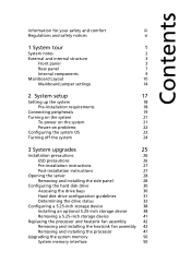
... 23 Turning off the system 24 3 System upgrades 25 Installation precautions 26 ESD precautions 26 Pre-installation instructions 27 Post-installation instructions 27 Opening the server 28 Removing and installing the side panel 28 Configuring the hard disk drive 30 Accessing the drive bays 30 Hard disk drive configuration guidelines 31...
... 23 Turning off the system 24 3 System upgrades 25 Installation precautions 26 ESD precautions 26 Pre-installation instructions 27 Post-installation instructions 27 Opening the server 28 Removing and installing the side panel 28 Configuring the hard disk drive 30 Accessing the drive bays 30 Hard disk drive configuration guidelines 31...
User Manual
Page 10
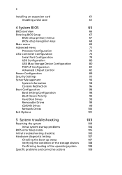
... Processor Configuration ATA Controller Configuration Serial Port Configuration USB Configuration USB Mass Storage Device Configuration PCI/PnP Configuration Advanced Chipset Control Power Configuration Security Settings Server Management System Information Console Redirection Boot Configuration Boot Setting Configuration Boot Device Priority Hard Disk Drives Removable Drives CD/DVD Drives Network Drives Exit Options...
... Processor Configuration ATA Controller Configuration Serial Port Configuration USB Configuration USB Mass Storage Device Configuration PCI/PnP Configuration Advanced Chipset Control Power Configuration Security Settings Server Management System Information Console Redirection Boot Configuration Boot Setting Configuration Boot Device Priority Hard Disk Drives Removable Drives CD/DVD Drives Network Drives Exit Options...
User Manual
Page 11
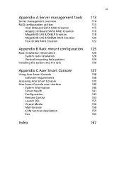
xi Appendix A Server management tools Server management overview RAID configuration utilities Intel Onboard SATA RAID Creation Adaptec Onboard SATA RAID Creation MegaRAID SAS 8204ELP Creation MegaRAID SAS 8708EM2 RAID ...Vertical mounting hole pattern Installing the system into the rack 125 126 128 129 130 Appendix C Acer Smart Console Using Acer Smart Console Software requirements Accessing Acer Smart Console Acer Smart Console user interface System Information Server Health Configuration Remote Control Launch SOL Virtual Media Maintenance KVM function description Exit 137 138 138 139...
xi Appendix A Server management tools Server management overview RAID configuration utilities Intel Onboard SATA RAID Creation Adaptec Onboard SATA RAID Creation MegaRAID SAS 8204ELP Creation MegaRAID SAS 8708EM2 RAID ...Vertical mounting hole pattern Installing the system into the rack 125 126 128 129 130 Appendix C Acer Smart Console Using Acer Smart Console Software requirements Accessing Acer Smart Console Acer Smart Console user interface System Information Server Health Configuration Remote Control Launch SOL Virtual Media Maintenance KVM function description Exit 137 138 138 139...
User Manual
Page 14
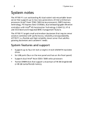
... supports up to two new generations of 96 GB (registered) or 48 GB (unbuffered) memory The AT150 F1 targets small and medium businesses that require server solution combined with Intel® I/O Acceleration Technology 2 (IOAT 2), VT-d and iSCSI boot and integrated BMC ... processors • Twelve DIMM slots that satisfies growing businesses and customers' needs. 2 1 System tour System notes The AT150 F1 is a flexible and high reliability tower server that support a maximum of Intel architecture processors (Intel® Xeon 5500 / 5600 series processors), DDR3 memory technology, PCI...
... supports up to two new generations of 96 GB (registered) or 48 GB (unbuffered) memory The AT150 F1 targets small and medium businesses that require server solution combined with Intel® I/O Acceleration Technology 2 (IOAT 2), VT-d and iSCSI boot and integrated BMC ... processors • Twelve DIMM slots that satisfies growing businesses and customers' needs. 2 1 System tour System notes The AT150 F1 is a flexible and high reliability tower server that support a maximum of Intel architecture processors (Intel® Xeon 5500 / 5600 series processors), DDR3 memory technology, PCI...
User Manual
Page 16
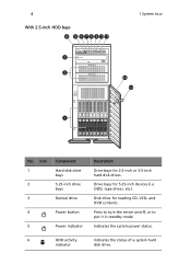
Icon 1 2 3 Component Hard disk drive bays 5.25-inch drive bays Optical drive 4 Power button 5 Power indicator Description Drive bays for reading CD, VCD, and DVD contents. ODD, tape drives, etc.) Disk drive for 2.5-inch or 3.5-inch hard disk drives. 4 With 2.5-inch HDD bays 1 System tour No. Press to turn the server on/off, or to put it in standby mode Indicates the system power status. 6 HDD activity Indicates the status of a system hard indicator disk drive. Drive bays for 5.25-inch devices (i.e.
Icon 1 2 3 Component Hard disk drive bays 5.25-inch drive bays Optical drive 4 Power button 5 Power indicator Description Drive bays for reading CD, VCD, and DVD contents. ODD, tape drives, etc.) Disk drive for 2.5-inch or 3.5-inch hard disk drives. 4 With 2.5-inch HDD bays 1 System tour No. Press to turn the server on/off, or to put it in standby mode Indicates the system power status. 6 HDD activity Indicates the status of a system hard indicator disk drive. Drive bays for 5.25-inch devices (i.e.

User Manual
Page 17
Bezel door Security keylock Unlock and open the bezel door to protect the server unit from unauthorized access. LAN port 1 activity Indicates the system network 1 indicator connection status. Icon 7 8 9 10 11 12 13 Component Description System status/...operations. System ID switch/ indicator Indicates if the system ID button is pressed or activated through IPMI. Secures the bezel door to power on the server and access the server's hard drives and USB ports. 5 No. LAN port 2 activity Indicates the system network 2 indicator connection status. USB 2.0 ports Connect to ...
Bezel door Security keylock Unlock and open the bezel door to protect the server unit from unauthorized access. LAN port 1 activity Indicates the system network 1 indicator connection status. Icon 7 8 9 10 11 12 13 Component Description System status/...operations. System ID switch/ indicator Indicates if the system ID button is pressed or activated through IPMI. Secures the bezel door to power on the server and access the server's hard drives and USB ports. 5 No. LAN port 2 activity Indicates the system network 2 indicator connection status. USB 2.0 ports Connect to ...
User Manual
Page 19
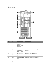
Icon 1 2 3 4 5 Component Dummy power supply module Server management port (10/100) PS/2 mouse port PS/2 keyboard port USB 2.0 ports Description Reserved for remote management of server. Connects to a PS/2 mouse. Connects to a PS/2 keyboard. 7 Rear panel No. Connect to USB devices.
Icon 1 2 3 4 5 Component Dummy power supply module Server management port (10/100) PS/2 mouse port PS/2 keyboard port USB 2.0 ports Description Reserved for remote management of server. Connects to a PS/2 mouse. Connects to a PS/2 keyboard. 7 Rear panel No. Connect to USB devices.
User Manual
Page 20
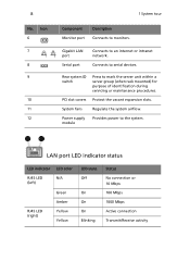
8 No. Connects to mark the server unit within a server group (when rack mounted) for purpose of identification during servicing or maintenance procedures. Rear system ID switch Press to serial devices. LAN port LED indicator ...
8 No. Connects to mark the server unit within a server group (when rack mounted) for purpose of identification during servicing or maintenance procedures. Rear system ID switch Press to serial devices. LAN port LED indicator ...
User Manual
Page 32
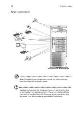
Caution: Do not route the power cord where it . The server is designed to configure the network setup. To ensure proper operation, plug the power cord into a properly grounded AC outlet only. 20 Rear connections 2 System setup Note: Consult the operating system manual for information on or pinched by items placed against it will be walked on how to be electrically grounded (earthed).
Caution: Do not route the power cord where it . The server is designed to configure the network setup. To ensure proper operation, plug the power cord into a properly grounded AC outlet only. 20 Rear connections 2 System setup Note: Consult the operating system manual for information on or pinched by items placed against it will be walked on how to be electrically grounded (earthed).
User Manual
Page 35
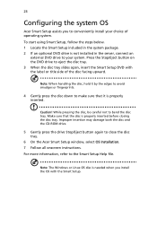
... the disc tray. Caution! For more information, refer to make sure that the disc is needed when you to close the disc tray. 6 On the Acer Smart Setup window, select OS Installation. 7 Follow all onscreen instructions. Note: When handling the disc, hold it is not installed in the system package. 2 If...it by the edges to avoid smudges or fingerprints. 4 Gently press the disc down to the Smart Setup Help file. 23 Configuring the system OS Acer Smart Setup assists you install the OS with the label or title side of operating system. To start using Smart Setup, follow the steps below...
... the disc tray. Caution! For more information, refer to make sure that the disc is needed when you to close the disc tray. 6 On the Acer Smart Setup window, select OS Installation. 7 Follow all onscreen instructions. Note: When handling the disc, hold it is not installed in the system package. 2 If...it by the edges to avoid smudges or fingerprints. 4 Gently press the disc down to the Smart Setup Help file. 23 Configuring the system OS Acer Smart Setup assists you install the OS with the label or title side of operating system. To start using Smart Setup, follow the steps below...
User Manual
Page 36
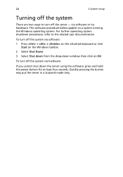
... via software: 1 Press + + on the attached keyboard or click Start on the Windows taskbar. 2 Select Shut Down. 3 Select Shut down from the drop-down the server using the software, press and hold the power button for at least four seconds. For further operating system shutdown procedures, refer to a system running the... cannot shut down window then click on OK. The software procedure below applies to the related user documentation. Quickly pressing the button may put the server in a Suspend mode only. To turn off the system via hardware.
... via software: 1 Press + + on the attached keyboard or click Start on the Windows taskbar. 2 Select Shut Down. 3 Select Shut down from the drop-down the server using the software, press and hold the power button for at least four seconds. For further operating system shutdown procedures, refer to a system running the... cannot shut down window then click on OK. The software procedure below applies to the related user documentation. Quickly pressing the button may put the server in a Suspend mode only. To turn off the system via hardware.
User Manual
Page 38
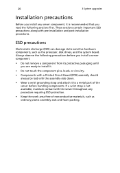
... precautions before handling components. These sections contain important ESD precautions along with the server throughout any procedure requiring ESD protection. • Keep the work area free of the server before you install a server component: • Do not remove a component from its protective packaging until ... contact with pre-installation and post-installation procedures. 26 3 System upgrades Installation precautions Before you install any server component, it to a metal part of nonconductive materials, such as the processor, disk drives, and the system board.
... precautions before handling components. These sections contain important ESD precautions along with the server throughout any procedure requiring ESD protection. • Keep the work area free of the server before you install a server component: • Do not remove a component from its protective packaging until ... contact with pre-installation and post-installation procedures. 26 3 System upgrades Installation precautions Before you install any server component, it to a metal part of nonconductive materials, such as the processor, disk drives, and the system board.
User Manual
Page 39
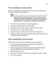
... step-by-step instructions. 2 Reinstall any component. Post-installation instructions Perform the steps below before you open the server or before you start perform any hardware configuration may cause serious damage and bodily harm. 27 Pre-installation instructions Perform... telecommunication cables. 5 Turn on page 38. 6 Follow the ESD precautions described in the previous section when handling a server component. Failure to properly turn off the server and all connected peripherals. 2 Unplug all power cables from their outlets. 3 Disconnect all telecommunication cables from their ports...
... step-by-step instructions. 2 Reinstall any component. Post-installation instructions Perform the steps below before you open the server or before you start perform any hardware configuration may cause serious damage and bodily harm. 27 Pre-installation instructions Perform... telecommunication cables. 5 Turn on page 38. 6 Follow the ESD precautions described in the previous section when handling a server component. Failure to properly turn off the server and all connected peripherals. 2 Unplug all power cables from their outlets. 3 Disconnect all telecommunication cables from their ports...
User Manual
Page 40
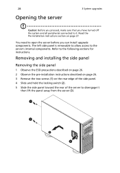
... the side panel. 4 Slide and hold the locking switch (2). 5 Slide the side panel toward the rear of the server to it then lift the panel away from the server (3). Removing and installing the side panel Removing the side panel 1 Observe the ESD precautions described on page 26. 2 ...allow access to the following sections for instructions. You need to open the server before you have turned off the system and all peripherals connected to disengage it . Refer to the server's internal components. 28 Opening the server 3 System upgrades Caution: Before you proceed, make sure that you can...
... the side panel. 4 Slide and hold the locking switch (2). 5 Slide the side panel toward the rear of the server to it then lift the panel away from the server (3). Removing and installing the side panel Removing the side panel 1 Observe the ESD precautions described on page 26. 2 ...allow access to the following sections for instructions. You need to open the server before you have turned off the system and all peripherals connected to disengage it . Refer to the server's internal components. 28 Opening the server 3 System upgrades Caution: Before you proceed, make sure that you can...

User Manual
Page 41
... the side panel so that the tabs on the server, then slide the side panel toward the front of the server until you need to four 3.5-inch or eight 2.5-inch hotplug SATA/SAS hard disk drives. Configuring the hard disk drive The AT150 F1 accommodates up to purchase the optional bay and SAS RAID...
... the side panel so that the tabs on the server, then slide the side panel toward the front of the server until you need to four 3.5-inch or eight 2.5-inch hotplug SATA/SAS hard disk drives. Configuring the hard disk drive The AT150 F1 accommodates up to purchase the optional bay and SAS RAID...
User Manual
Page 46
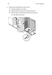
34 3 System upgrades 4 Remove the hard disk drive with carrier. (1) Unlock the HDD carrier latch. (2) Slide the HDD carrier latch to release the lever. (3) Pull the lever and slide the carrier from the server. 3.5-inch HDD with carrier
34 3 System upgrades 4 Remove the hard disk drive with carrier. (1) Unlock the HDD carrier latch. (2) Slide the HDD carrier latch to release the lever. (3) Pull the lever and slide the carrier from the server. 3.5-inch HDD with carrier
User Manual
Page 47
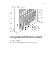
35 2.5-inch HDD with carrier 5 If you have no plans of installing a new HDD to the server, you must reinstall the blank HDD carrier or HDD cover to maintain proper airflow. 6 Close the bezel door. 7 Observe the post-installation instructions on page 27.
35 2.5-inch HDD with carrier 5 If you have no plans of installing a new HDD to the server, you must reinstall the blank HDD carrier or HDD cover to maintain proper airflow. 6 Close the bezel door. 7 Observe the post-installation instructions on page 27.
User Manual
Page 54
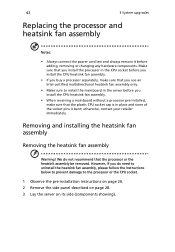
... assembly Warning! We do need to uninstall the heatsink fan assembly, please follow the instructions below to prevent damage to install the mainboard in the server before adding, removing or changing any hardware components. Make sure that you install the processor in place and none of the socket pins is bent... to the processor or the CPU socket. 1 Observe the pre-installation instructions on page 26. 2 Remove the side panel described on page 28. 3 Lay the server on its side (components showing).
... assembly Warning! We do need to uninstall the heatsink fan assembly, please follow the instructions below to prevent damage to install the mainboard in the server before adding, removing or changing any hardware components. Make sure that you install the processor in place and none of the socket pins is bent... to the processor or the CPU socket. 1 Observe the pre-installation instructions on page 26. 2 Remove the side panel described on page 28. 3 Lay the server on its side (components showing).
User Manual
Page 57
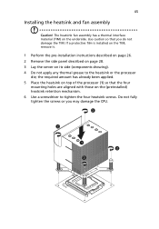
... installed on the TIM, remove it. 1 Perform the pre-installation instructions described on page 26. 2 Remove the side panel described on page 28. 3 Lay the server on the underside. The heatsink fan assembly has a thermal interface material (TIM) on its side (components showing). 4 Do not apply any thermal grease to tighten...
... installed on the TIM, remove it. 1 Perform the pre-installation instructions described on page 26. 2 Remove the side panel described on page 28. 3 Lay the server on the underside. The heatsink fan assembly has a thermal interface material (TIM) on its side (components showing). 4 Do not apply any thermal grease to tighten...
User Manual
Page 59
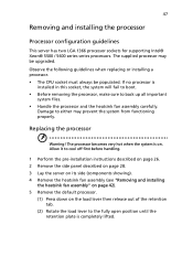
...cool off first before handling. 1 Perform the pre-installation instructions described on page 26. 2 Remove the side panel described on page 28. 3 Lay the server on its side (components showing). 4 Remove the heatsink fan assembly (see "Removing and installing the heatsink fan assembly" on page 42). 5 Remove the ... system files. • Handle the processor and the heatsink fan assembly carefully. 47 Removing and installing the processor Processor configuration guidelines This server has two LGA 1366 processor sockets for supporting Intel® Xeon® 5500 / 5600 series series processors.
...cool off first before handling. 1 Perform the pre-installation instructions described on page 26. 2 Remove the side panel described on page 28. 3 Lay the server on its side (components showing). 4 Remove the heatsink fan assembly (see "Removing and installing the heatsink fan assembly" on page 42). 5 Remove the ... system files. • Handle the processor and the heatsink fan assembly carefully. 47 Removing and installing the processor Processor configuration guidelines This server has two LGA 1366 processor sockets for supporting Intel® Xeon® 5500 / 5600 series series processors.


