User Manual
Page 14
... Gen2 (5.0Gb/s), dual onboard gigabit Ethernet controllers with performance, reliability and expandability. AT150 F1 is an outstanding 4U dual socket rack-mountable tower server that supports up to two new generations of 96 GB (registered) or 48 GB (unbuffered) memory The AT150 F1 targets small and medium businesses that require server solution combined with Intel...
... Gen2 (5.0Gb/s), dual onboard gigabit Ethernet controllers with performance, reliability and expandability. AT150 F1 is an outstanding 4U dual socket rack-mountable tower server that supports up to two new generations of 96 GB (registered) or 48 GB (unbuffered) memory The AT150 F1 targets small and medium businesses that require server solution combined with Intel...
User Manual
Page 24
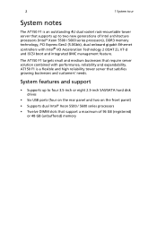
... 44 Slot5 45 LAN CTRL 46 Slot6 47 FAN8/CPU1 48 UID SW1 49 CPU1 1 System tour Description Front panel accessible USB connections Trusted Platform Support Header Serial connector 2 Chassis intrusion header For debug only IPMB header (for an IPMI card) Watch Dog jumper Onboard battery holder PCI-E x8 slot (x4...
... 44 Slot5 45 LAN CTRL 46 Slot6 47 FAN8/CPU1 48 UID SW1 49 CPU1 1 System tour Description Front panel accessible USB connections Trusted Platform Support Header Serial connector 2 Chassis intrusion header For debug only IPMB header (for an IPMI card) Watch Dog jumper Onboard battery holder PCI-E x8 slot (x4...

User Manual
Page 41
... disk drive bay, you hear a click sound. 3 Replace the two screws. Note: Maximum HDD support is shipped with the slots on the cover align with only one hard disk drive bay. Configuring the hard disk drive The AT150 F1 accommodates up to purchase the optional bay and SAS RAID controller. 29 Installing the...
... disk drive bay, you hear a click sound. 3 Replace the two screws. Note: Maximum HDD support is shipped with the slots on the cover align with only one hard disk drive bay. Configuring the hard disk drive The AT150 F1 accommodates up to purchase the optional bay and SAS RAID controller. 29 Installing the...
User Manual
Page 42
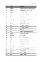
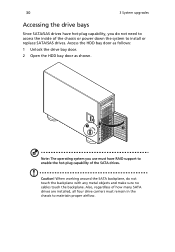
...: 1 Unlock the drive bay door. 2 Open the HDD bay door as shown. 30 3 System upgrades Accessing the drive bays Since SATA/SAS drives have RAID support to enable the hot-plug capability of the SATA drives.
...: 1 Unlock the drive bay door. 2 Open the HDD bay door as shown. 30 3 System upgrades Accessing the drive bays Since SATA/SAS drives have RAID support to enable the hot-plug capability of the SATA drives.
User Manual
Page 44
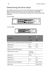
... checking the hot-plug HDD status indicators. 3.5-inch HDD 2.5-inch HDD Description Green Onboard SATA or RAID card without SGPIO support HDD present On HDD access Blink RAID card with SGPIO support HDD present no access SAS: On SATA:Off HDD access Blink HDD failure HDD removal Off HDD insertion and rebuilding...
... checking the hot-plug HDD status indicators. 3.5-inch HDD 2.5-inch HDD Description Green Onboard SATA or RAID card without SGPIO support HDD present On HDD access Blink RAID card with SGPIO support HDD present no access SAS: On SATA:Off HDD access Blink HDD failure HDD removal Off HDD insertion and rebuilding...
User Manual
Page 50
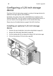
...-inch drive cage. 4 Pull out the dummy 5.25-inch drive cage (2). 38 3 System upgrades Configuring a 5.25-inch storage device The three 5.25-inch device bays support a variety of storage devices for additional storage capacity and scalability. By default, the system ships with a DVD-ROM drive installed on the second device bay...
...-inch drive cage. 4 Pull out the dummy 5.25-inch drive cage (2). 38 3 System upgrades Configuring a 5.25-inch storage device The three 5.25-inch device bays support a variety of storage devices for additional storage capacity and scalability. By default, the system ships with a DVD-ROM drive installed on the second device bay...
User Manual
Page 59
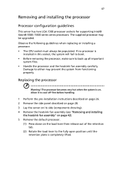
... processor and the heatsink fan assembly carefully. 47 Removing and installing the processor Processor configuration guidelines This server has two LGA 1366 processor sockets for supporting Intel® Xeon® 5500 / 5600 series series processors.
... processor and the heatsink fan assembly carefully. 47 Removing and installing the processor Processor configuration guidelines This server has two LGA 1366 processor sockets for supporting Intel® Xeon® 5500 / 5600 series series processors.
User Manual
Page 62
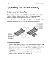
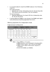
... slot B cannot be populated first and then slot B. Independent mode • For all memory modes, slot A in each channel has two slots. The DIMM slots support DDR3-1333 registered/unbuffered ECC memory modules.
... slot B cannot be populated first and then slot B. Independent mode • For all memory modes, slot A in each channel has two slots. The DIMM slots support DDR3-1333 registered/unbuffered ECC memory modules.
User Manual
Page 63
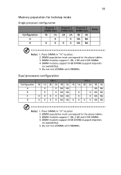
DIMM modules support 1 GB, 2 GB and 4 GB DIMMs. 4. 51 • It is recommended to the above tables. 3. DIMM population must correspond to install the DIMM modules in the ... slots 3B 3A X X X X X X X X X Notes SR, DR RDIMMs only Notes: 1. Do not mix UDIMMs with higher rank and density should be populated from slot A. DIMM modules support 8 GB (support depends on availability). 5. Memory population for processor 2 are not available. Place DIMMs in one channel, the DIMM with RDIMMs.
DIMM modules support 1 GB, 2 GB and 4 GB DIMMs. 4. 51 • It is recommended to the above tables. 3. DIMM population must correspond to install the DIMM modules in the ... slots 3B 3A X X X X X X X X X Notes SR, DR RDIMMs only Notes: 1. Do not mix UDIMMs with higher rank and density should be populated from slot A. DIMM modules support 8 GB (support depends on availability). 5. Memory population for processor 2 are not available. Place DIMMs in one channel, the DIMM with RDIMMs.
User Manual
Page 64
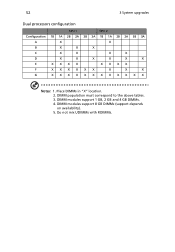
DIMM population must correspond to the above tables. 3. DIMM modules support 8 GB DIMMs (support depends on availability). 5. DIMM modules support 1 GB, 2 GB and 4 GB DIMMs. 4. Place DIMMs in "X" location. 2. Do not mix UDIMMs with RDIMMs. 52 3 System upgrades Dual processors configuration CPU 1 CPU 2 Configuration 1B 1A 2B 2A 3B 3A 1B 1A 2B 2A 3B 3A A X X B X X X C X X X X D X X X X X X E XXXX XXXX F XXXXXX X X X G XXXXXXXXXXXX Notes: 1.
DIMM population must correspond to the above tables. 3. DIMM modules support 8 GB DIMMs (support depends on availability). 5. DIMM modules support 1 GB, 2 GB and 4 GB DIMMs. 4. Place DIMMs in "X" location. 2. Do not mix UDIMMs with RDIMMs. 52 3 System upgrades Dual processors configuration CPU 1 CPU 2 Configuration 1B 1A 2B 2A 3B 3A 1B 1A 2B 2A 3B 3A A X X B X X X C X X X X D X X X X X X E XXXX XXXX F XXXXXX X X X G XXXXXXXXXXXX Notes: 1.
User Manual
Page 65
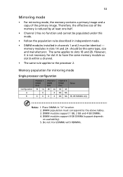
The same applies to the processor 2. Place DIMMs in slots 1A and 2A should be identical - Do not mix UDIMMs with RDIMMs. DIMM modules support 1 GB, 2 GB and 4 GB DIMMs. 4. However, it is reduced by at least one-half. • Channel 3 has no ...must correspond to the above tables. 3. DIMM population must be the same type, size and manufacturer. memory modules in "X" location. 2. DIMM modules support 8 GB DIMMs (support depends on availability). 5. Therefore, the effective size of the primary image. 53 Mirroring mode • For mirroring mode, the memory contains a ...
The same applies to the processor 2. Place DIMMs in slots 1A and 2A should be identical - Do not mix UDIMMs with RDIMMs. DIMM modules support 1 GB, 2 GB and 4 GB DIMMs. 4. However, it is reduced by at least one-half. • Channel 3 has no ...must correspond to the above tables. 3. DIMM population must be the same type, size and manufacturer. memory modules in "X" location. 2. DIMM modules support 8 GB DIMMs (support depends on availability). 5. Therefore, the effective size of the primary image. 53 Mirroring mode • For mirroring mode, the memory contains a ...
User Manual
Page 66
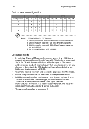
... Channel 3 has no function and cannot be the same type, size and manufacturer. Do not mix UDIMMs with 8-bit wide data ports. DIMM modules support 1 GB, 2 GB and 4 GB DIMMs. 4. However, it is not necessary for DRAM devices with RDIMMs. Lockstep mode • In Lockstep ...this mode. • Follow the population rules described in independent mode. • DIMM modules installed in "X" location. 2. DIMM modules support 8 GB DIMMs (support depends on any channel is the only RAS mode that an address error on availability). 5. Lockstep Channel mode is detectable by ECC. ...
... Channel 3 has no function and cannot be the same type, size and manufacturer. Do not mix UDIMMs with 8-bit wide data ports. DIMM modules support 1 GB, 2 GB and 4 GB DIMMs. 4. However, it is not necessary for DRAM devices with RDIMMs. Lockstep mode • In Lockstep ...this mode. • Follow the population rules described in independent mode. • DIMM modules installed in "X" location. 2. DIMM modules support 8 GB DIMMs (support depends on any channel is the only RAS mode that an address error on availability). 5. Lockstep Channel mode is detectable by ECC. ...
User Manual
Page 67
... tables. 3. Do not mix UDIMMs with RDIMMs. DIMM modules support 8 GB DIMMs (support depends on availability). 5. DIMM modules support 8 GB DIMMs (support depends on availability). 5. DIMM population must correspond to the above tables. 3. Place DIMMs in "X" location. 2. DIMM modules support 1 GB, 2 GB and 4 GB DIMMs. 4. DIMM modules support 1 GB, 2 GB and 4 GB DIMMs. 4. 55 Memory population...
... tables. 3. Do not mix UDIMMs with RDIMMs. DIMM modules support 8 GB DIMMs (support depends on availability). 5. DIMM modules support 8 GB DIMMs (support depends on availability). 5. DIMM population must correspond to the above tables. 3. Place DIMMs in "X" location. 2. DIMM modules support 1 GB, 2 GB and 4 GB DIMMs. 4. DIMM modules support 1 GB, 2 GB and 4 GB DIMMs. 4. 55 Memory population...
User Manual
Page 68
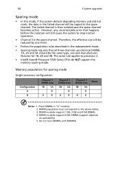
DIMM modules support 1 GB, 2 GB and 4 GB DIMMs. 4. 56 3 System upgrades Sparing mode • In this mode, if the ... slots 2B 2A X X X Channel 3 DIMM slots 3B 3A X X X Notes Notes: 1. The failed channel is the spare channel. DIMM modules support 8 GB DIMMs (support depends on availability). 5. Therefore, the effective size will still cause the system to the spare channel. Do not mix UDIMMs with RDIMMs. However, any... 3B. DIMM population must correspond to processor 2. • Intel® Xeon® Processor 5500 Series CPUs do NOT support the memory sparing mode.
DIMM modules support 1 GB, 2 GB and 4 GB DIMMs. 4. 56 3 System upgrades Sparing mode • In this mode, if the ... slots 2B 2A X X X Channel 3 DIMM slots 3B 3A X X X Notes Notes: 1. The failed channel is the spare channel. DIMM modules support 8 GB DIMMs (support depends on availability). 5. Therefore, the effective size will still cause the system to the spare channel. Do not mix UDIMMs with RDIMMs. However, any... 3B. DIMM population must correspond to processor 2. • Intel® Xeon® Processor 5500 Series CPUs do NOT support the memory sparing mode.
User Manual
Page 69
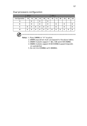
DIMM modules support 1 GB, 2 GB and 4 GB DIMMs. 4. Do not mix UDIMMs with RDIMMs. 57 Dual processors configuration CPU 1 CPU 2 Configuration 1B 1A 2B 2A 3B 3A 1B 1A 2B 2A 3B 3A A X X X B X X X X X X C XXXXXX X X X D XXXXXXXXXXXX Notes: 1. Place DIMMs in "X" location. 2. DIMM modules support 8 GB DIMMs (support depends on availability). 5. DIMM population must correspond to the above tables. 3.
DIMM modules support 1 GB, 2 GB and 4 GB DIMMs. 4. Do not mix UDIMMs with RDIMMs. 57 Dual processors configuration CPU 1 CPU 2 Configuration 1B 1A 2B 2A 3B 3A 1B 1A 2B 2A 3B 3A A X X X B X X X X X X C XXXXXX X X X D XXXXXXXXXXXX Notes: 1. Place DIMMs in "X" location. 2. DIMM modules support 8 GB DIMMs (support depends on availability). 5. DIMM population must correspond to the above tables. 3.
User Manual
Page 70
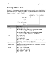
Note: It is used, a maximum of the DIMM module. This platform supports x4 and x8. PC3 - 6400 => DDR3- 800 PC3 - 8500 => DDR3- 1066 PC3 - 10600 => DDR3- 1333 PC3 - 12800 => DDR3- ... organization Speed Description 1 GB, 2 GB, 4 GB, 8 GB. • Intel Xeon 5500 series processor supports DIMM organized by 1Gb or 2Gb DRAM chips. • Intel Xeon 5600 series processor supports DIMM organized by 1Gb, 2Gb or 4Gb DRAM chips. 1R = Single Rank 2R = Dual Rank 4R =... identification Generally, there are some memory information printed on the label of only two DIMMs per channel can be supported.
Note: It is used, a maximum of the DIMM module. This platform supports x4 and x8. PC3 - 6400 => DDR3- 800 PC3 - 8500 => DDR3- 1066 PC3 - 10600 => DDR3- 1333 PC3 - 12800 => DDR3- ... organization Speed Description 1 GB, 2 GB, 4 GB, 8 GB. • Intel Xeon 5500 series processor supports DIMM organized by 1Gb or 2Gb DRAM chips. • Intel Xeon 5600 series processor supports DIMM organized by 1Gb, 2Gb or 4Gb DRAM chips. 1R = Single Rank 2R = Dual Rank 4R =... identification Generally, there are some memory information printed on the label of only two DIMMs per channel can be supported.
User Manual
Page 84
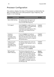
...both cache lines for 128 bytes as comprised if this feature is set to Enabled. Enabled Disabled Adjacent Cache Line Prefetch (Available when supported by the BIOS, including items such as the processor's type, frequency, and Cache L1, L2, L3 settings. Select Modern Ordering...ACPI MADT Ordering This feature allows the user to enable Enhanced Halt State support. Enabled Disabled Hardware Prefetcher (Available when supported by reducing the CPU's clock cycle and voltage during a Halt State. C1E Support Select Enabled to configure the MPS (Multi-Processor Specifi cations) and ...
...both cache lines for 128 bytes as comprised if this feature is set to Enabled. Enabled Disabled Adjacent Cache Line Prefetch (Available when supported by the BIOS, including items such as the processor's type, frequency, and Cache L1, L2, L3 settings. Select Modern Ordering...ACPI MADT Ordering This feature allows the user to enable Enhanced Halt State support. Enabled Disabled Hardware Prefetcher (Available when supported by reducing the CPU's clock cycle and voltage during a Halt State. C1E Support Select Enabled to configure the MPS (Multi-Processor Specifi cations) and ...
User Manual
Page 85
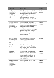
73 Parameter Intel® Virtualization Technology (Available when supported by the CPU) Execute-Disable Bit Capability (Available if supported by the OS & the CPU) Simultaneous Multi-Threading (Available when supported by the CPU) Active Processor Cores Intel® EIST Technology Intel® ...Turbo Boost (Available when Intel® EIST Technology is enabled) Description Options Select Enabled to enable Intel Virtualization Technology support, which will allow one platform to run multiple operating systems and applications in independent partitions, creating multiple "virtual" systems...
73 Parameter Intel® Virtualization Technology (Available when supported by the CPU) Execute-Disable Bit Capability (Available if supported by the OS & the CPU) Simultaneous Multi-Threading (Available when supported by the CPU) Active Processor Cores Intel® EIST Technology Intel® ...Turbo Boost (Available when Intel® EIST Technology is enabled) Description Options Select Enabled to enable Intel Virtualization Technology support, which will allow one platform to run multiple operating systems and applications in independent partitions, creating multiple "virtual" systems...
User Manual
Page 87
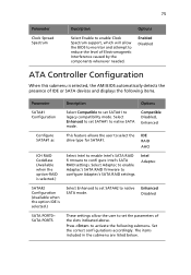
... the components whenever needed. Press to select the drive type for SATA#1. 75 Parameter Clock Spread Spectrum Description Options Select Enable to enable Clock Spectrum support, which will allow the user to set the parameters of the slots indicated above. Enhanced Disabled SATA PORT0~ SATA PORT5 These settings allow the BIOS...
... the components whenever needed. Press to select the drive type for SATA#1. 75 Parameter Clock Spread Spectrum Description Options Select Enable to enable Clock Spectrum support, which will allow the user to set the parameters of the slots indicated above. Enhanced Disabled SATA PORT0~ SATA PORT5 These settings allow the BIOS...
User Manual
Page 88
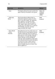
...-bit LBA mode If not, contact your manufacturer or install an ATA/133 IDE controller card that supports 48-bit LBA mode. The maximum drive capacity is a method of addressing data on a disk drive In the LBA mode. Auto Disabled Block Mode boosts ...
...-bit LBA mode If not, contact your manufacturer or install an ATA/133 IDE controller card that supports 48-bit LBA mode. The maximum drive capacity is a method of addressing data on a disk drive In the LBA mode. Auto Disabled Block Mode boosts ...

