User Manual
Page 8
viii Installing an additional hard drive Configuring a 5-25 inch storage device Upgrading the processor Upgrading the system memory Installing an expansion card Installing the TPM module Installing the System Fan module Installing a redundant power supply module 4 System BIOS BIOS overview Entering BIOS setup BIOS setup primary menus BIOS setup navigation keys Main menu Advanced menu...
viii Installing an additional hard drive Configuring a 5-25 inch storage device Upgrading the processor Upgrading the system memory Installing an expansion card Installing the TPM module Installing the System Fan module Installing a redundant power supply module 4 System BIOS BIOS overview Entering BIOS setup BIOS setup primary menus BIOS setup navigation keys Main menu Advanced menu...

User Manual
Page 17
... options Note: To purchase the any of the following hardware options, contact your local Acer representative. • Intel® Xeon® processor 5500 series: • 2.66...4 MB shared cache, 4.80 GT/s QPI • 1.86 GHz with 4 MB shared cache, 4.80 GT/s QPI • Memory • Registered DDR3 1333 MHz ECC DIMMs: 1/2/4/8 GB • Unbuffered DDR3 1333 MHz ECC DIMMs: 1/2/4 GB • HDD... GB • 3.5" SATA 3 Gb/s HDD: 320/500/640 GB, 1/1.5 TB • Daughter cards/modules: • TPM module • Add-on cards: • ASC/3S single-channel U320 SCSI HBA (for backup device) •...
... options Note: To purchase the any of the following hardware options, contact your local Acer representative. • Intel® Xeon® processor 5500 series: • 2.66...4 MB shared cache, 4.80 GT/s QPI • 1.86 GHz with 4 MB shared cache, 4.80 GT/s QPI • Memory • Registered DDR3 1333 MHz ECC DIMMs: 1/2/4/8 GB • Unbuffered DDR3 1333 MHz ECC DIMMs: 1/2/4 GB • HDD... GB • 3.5" SATA 3 Gb/s HDD: 320/500/640 GB, 1/1.5 TB • Daughter cards/modules: • TPM module • Add-on cards: • ASC/3S single-channel U320 SCSI HBA (for backup device) •...

User Manual
Page 86
... empty, socket 2 can't be channel D,E &F. The DIMM slots support three channel DDR3-1333 registered/ unbuffered ECC memory modules. Memory Configuration Guideline Altos G540 M2 has twelve DIMM slots. For all memory modes, the socket 1 in each channel should install the memory module into DIMM A1 to CPU is socket 1 (A1,B1,C1,D1,E1,F1 in color black). The...
... empty, socket 2 can't be channel D,E &F. The DIMM slots support three channel DDR3-1333 registered/ unbuffered ECC memory modules. Memory Configuration Guideline Altos G540 M2 has twelve DIMM slots. For all memory modes, the socket 1 in each channel should install the memory module into DIMM A1 to CPU is socket 1 (A1,B1,C1,D1,E1,F1 in color black). The...

User Manual
Page 87
... manufacturer must be installed in the same colored DIMM slots. • CPU 1 - 77 (2) The DIMM D1 to function, DIMM modules must be installed following the slot sequence listed below when installing a memory module. For the system to DIMM F2 slots are enabled when a second CPU is installed on the mainboard. Independent Mode: Singel... 2GB 2GB 2GB 2GB Populate DIMM slots A1 first, followed by slots E1, F1, D2, E2, and F2. • To ensure data integrity, use only Acer-approved 240-pin, DDR3 Registered/Unbufferred DIMM ECC modules in the table below .
... manufacturer must be installed in the same colored DIMM slots. • CPU 1 - 77 (2) The DIMM D1 to function, DIMM modules must be installed following the slot sequence listed below when installing a memory module. For the system to DIMM F2 slots are enabled when a second CPU is installed on the mainboard. Independent Mode: Singel... 2GB 2GB 2GB 2GB Populate DIMM slots A1 first, followed by slots E1, F1, D2, E2, and F2. • To ensure data integrity, use only Acer-approved 240-pin, DDR3 Registered/Unbufferred DIMM ECC modules in the table below .

User Manual
Page 88
... 8GB 8GB 8GB 8GB Note: *Support depends on 8GB DIMM available Dual processor configuration Observe the population sequence illustrated in the table below when installing a memory module.
... 8GB 8GB 8GB 8GB Note: *Support depends on 8GB DIMM available Dual processor configuration Observe the population sequence illustrated in the table below when installing a memory module.

User Manual
Page 129
... Sets the temperature rise parameter of the location where the system is used. System Altitude Sets the altitude of a memory module to the DIMMs Sets the speed of physical space DIMMs between each memory module. Temperature Chassis inlet Temperature detected at the chassis inlet. 121 Thermal and Acoustic Configuration Parameter Description Open-loop Thermal...
... Sets the temperature rise parameter of the location where the system is used. System Altitude Sets the altitude of a memory module to the DIMMs Sets the speed of physical space DIMMs between each memory module. Temperature Chassis inlet Temperature detected at the chassis inlet. 121 Thermal and Acoustic Configuration Parameter Description Open-loop Thermal...

User Manual
Page 130
...location 0 Altitude where the system is used. Temperature Rise Sets the temperature rise parameter 10 of physical space 400 DIMMs between each memory module. Enabled Disabled Temperature Sets the temperature hysteresis. 1 Hysteresis Temperature Sets the temperature guardband. 3 Guardband Temperature Chassis inlet Temperature detected at... Option Close-loop Thermal Throttle Enables or disables close-loop thermal throttle control function when the projected memory temperature exceeds a predefined limit. Air Speed to the DIMMs Sets the speed of air flow to improve...
...location 0 Altitude where the system is used. Temperature Rise Sets the temperature rise parameter 10 of physical space 400 DIMMs between each memory module. Enabled Disabled Temperature Sets the temperature hysteresis. 1 Hysteresis Temperature Sets the temperature guardband. 3 Guardband Temperature Chassis inlet Temperature detected at... Option Close-loop Thermal Throttle Enables or disables close-loop thermal throttle control function when the projected memory temperature exceeds a predefined limit. Air Speed to the DIMMs Sets the speed of air flow to improve...

User Manual
Page 150
... properly installed. • Make sure the power cord is causing the problem. • Make sure that you have properly installed system compliant memory modules, and that there populated according to the system guidelines. 142 5 System troubleshooting Specific problems and corrective actions Listed below are specific problems that may arise ...
... properly installed. • Make sure the power cord is causing the problem. • Make sure that you have properly installed system compliant memory modules, and that there populated according to the system guidelines. 142 5 System troubleshooting Specific problems and corrective actions Listed below are specific problems that may arise ...
User Manual
Page 151
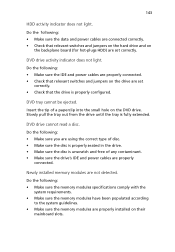
Do the following : • Make sure the memory modules specifications comply with the system requirements. • Make sure the memory modules have been populated according to the system guidelines. • Make sure the memory modules are properly installed on the DVD drive. DVD drive activity indicator does not... and jumpers on the backplane board (for hot-plugs HDD) are set correctly. DVD drive cannot read a disc. Newly installed memory modules are properly connected. Do the following : • Make sure the IDE and power cables are properly connected. • Check that...
Do the following : • Make sure the memory modules specifications comply with the system requirements. • Make sure the memory modules have been populated according to the system guidelines. • Make sure the memory modules are properly installed on the DVD drive. DVD drive activity indicator does not... and jumpers on the backplane board (for hot-plugs HDD) are set correctly. DVD drive cannot read a disc. Newly installed memory modules are properly connected. Do the following : • Make sure the IDE and power cables are properly connected. • Check that...

User Manual
Page 153
Take note of them is causing the problem. • Make sure that you have properly installed system compliant memory modules, and that there populated according to the system guidelines. • Make sure that you reboot the system, reboot it by turning the Num Lock .... Test it again. If you are still no characters on and off to the system guidelines. If you seek technical assistance. Contact your local Acer representative or authorized dealer for the changes to the correct system? • Are the brightness and contrast controls on the display monitor. Check the ...
Take note of them is causing the problem. • Make sure that you have properly installed system compliant memory modules, and that there populated according to the system guidelines. • Make sure that you reboot the system, reboot it by turning the Num Lock .... Test it again. If you are still no characters on and off to the system guidelines. If you seek technical assistance. Contact your local Acer representative or authorized dealer for the changes to the correct system? • Are the brightness and contrast controls on the display monitor. Check the ...
User Manual
Page 220
...speed indicator 27 troubleshooting 144 LED indicators front panel 24 HDD carrier 26 LAN port 27 M mechanical specifications chassis 6 media storage specification 4 memory install 85 population order 79 remove 83 troubleshooting 143 monitor port 14 O Onboard SATA RAID Configuration Utility 150 operating system configure 36 support ... 11 indicator, status 24 troubleshooting 142 turn off 38 turn on 33 power off via hardware 38 via software 38 power supply module fault indicator, location 13 install 94 redundant bay 15 release latch 13 status indicator, location 13 power-on password 125 power-on...
...speed indicator 27 troubleshooting 144 LED indicators front panel 24 HDD carrier 26 LAN port 27 M mechanical specifications chassis 6 media storage specification 4 memory install 85 population order 79 remove 83 troubleshooting 143 monitor port 14 O Onboard SATA RAID Configuration Utility 150 operating system configure 36 support ... 11 indicator, status 24 troubleshooting 142 turn off 38 turn on 33 power off via hardware 38 via software 38 power supply module fault indicator, location 13 install 94 redundant bay 15 release latch 13 status indicator, location 13 power-on password 125 power-on...

User Manual
Page 221
...storage device 64 ESD precautions 41 expansion card 88 hard drive 45 installation precautions 41 memory 78 post-installation instructions 42 preinstallation instructions 42 processor 70 redundant power supply module 94 T thermal grease 74 troubleshooting display problems 145 DVD-ROM drive problems 143 FAQ ...142 hardware diagnostics 140 HDD problem 143 initial checklist 139 initial startup problems 138 memory problem 143 network problems 144 power ...
...storage device 64 ESD precautions 41 expansion card 88 hard drive 45 installation precautions 41 memory 78 post-installation instructions 42 preinstallation instructions 42 processor 70 redundant power supply module 94 T thermal grease 74 troubleshooting display problems 145 DVD-ROM drive problems 143 FAQ ...142 hardware diagnostics 140 HDD problem 143 initial checklist 139 initial startup problems 138 memory problem 143 network problems 144 power ...
