User Manual
Page 7
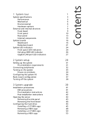
... Gigabit LAN port LED indicators 27 2 System setup 29 Setting up the system 31 Pre-installation requirements 31 Connecting peripherals 32 Turning on the system 33 Power-on problems 34 Configuring the system OS 36 Rack mount configuration 37 Turning off the system 38 3 System upgrade 39 Installation precautions 41 ESD precautions 41 Pre-installation instructions 42 Post-installation instructions 42 Opening the server 43 Removing the side panel 43 Removing the front bezel 44 Configuring the hard drive 45 Installing a 3.5"HDD...
... Gigabit LAN port LED indicators 27 2 System setup 29 Setting up the system 31 Pre-installation requirements 31 Connecting peripherals 32 Turning on the system 33 Power-on problems 34 Configuring the system OS 36 Rack mount configuration 37 Turning off the system 38 3 System upgrade 39 Installation precautions 41 ESD precautions 41 Pre-installation instructions 42 Post-installation instructions 42 Opening the server 43 Removing the side panel 43 Removing the front bezel 44 Configuring the hard drive 45 Installing a 3.5"HDD...
User Manual
Page 8
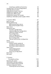
... System Fan module Installing a redundant power supply module 4 System BIOS BIOS overview Entering BIOS setup BIOS setup primary menus BIOS setup navigation keys Main menu Advanced menu Processor Configuration Advanced Memory Configuration Advanced Chipset Control PCI Configuration SATA Configuration I/O Device Configuration Boot Configuration Thermal and Acoustic Configuration Power Security menu Setting a system password Changing a system password Removing a system password Server menu System Management Console Redirection Event Log Configuration Boot menu Exit menu 5 System troubleshooting...
... System Fan module Installing a redundant power supply module 4 System BIOS BIOS overview Entering BIOS setup BIOS setup primary menus BIOS setup navigation keys Main menu Advanced menu Processor Configuration Advanced Memory Configuration Advanced Chipset Control PCI Configuration SATA Configuration I/O Device Configuration Boot Configuration Thermal and Acoustic Configuration Power Security menu Setting a system password Changing a system password Removing a system password Server menu System Management Console Redirection Event Log Configuration Boot menu Exit menu 5 System troubleshooting...
User Manual
Page 9
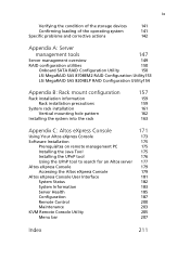
... Rack installation precautions System rack installation Vertical mounting hole pattern Installing the system into the rack 157 159 159 161 162 163 Appendix C: Altos eXpress Console Using Your Altos eXpress Console Software Installation Prerequisites on remote management PC Installing the Java Tool Installing the UPnP tool Using the UPnP tool to search for an Altos server Altos eXpress Console Accessing the Altos eXpress Console Altos eXpress Console User Interface System Status System Information Server Health Configuration Remote Control Maintenance KVM Remote Console Utility Menu...
... Rack installation precautions System rack installation Vertical mounting hole pattern Installing the system into the rack 157 159 159 161 162 163 Appendix C: Altos eXpress Console Using Your Altos eXpress Console Software Installation Prerequisites on remote management PC Installing the Java Tool Installing the UPnP tool Using the UPnP tool to search for an Altos server Altos eXpress Console Accessing the Altos eXpress Console Altos eXpress Console User Interface System Status System Information Server Health Configuration Remote Control Maintenance KVM Remote Console Utility Menu...
User Manual
Page 29
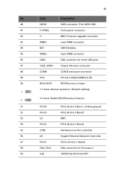
.... Code Description 40 SATA5 SATA connector 5 for SATA ODD 41 F_PANEL Front panel connector 42 J1 BMC firmware upgrade connector 43 IPMB1 3-pin IPMB connector 44 BAT CMOS Battery 45 IPMB2 4-pin IPMB connector 46 USB2 USB connector for front USB ports 47 CASE_OPEN Chassis Intrusion connector 48 COMB COM B serial port connector 49 PCI5 PCI slot 5 (32bit/33MHz/3.3V) 50 BIOS_RVCR BIOS Recovery Jumper 1-2 close: Normal operation. (Default setting) 2-3 close: Enable BIOS Recovery function 51 PCI-E4 PCI-E x8 slot 4 (Gen1, x4 throughput) 52 PCI-E3 PCI-E x8 slot...
.... Code Description 40 SATA5 SATA connector 5 for SATA ODD 41 F_PANEL Front panel connector 42 J1 BMC firmware upgrade connector 43 IPMB1 3-pin IPMB connector 44 BAT CMOS Battery 45 IPMB2 4-pin IPMB connector 46 USB2 USB connector for front USB ports 47 CASE_OPEN Chassis Intrusion connector 48 COMB COM B serial port connector 49 PCI5 PCI slot 5 (32bit/33MHz/3.3V) 50 BIOS_RVCR BIOS Recovery Jumper 1-2 close: Normal operation. (Default setting) 2-3 close: Enable BIOS Recovery function 51 PCI-E4 PCI-E x8 slot 4 (Gen1, x4 throughput) 52 PCI-E3 PCI-E x8 slot...
User Manual
Page 31
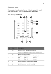
Code 1 J14 2 J16 3 J15 4 J3 5 J2 Description Close 1-2: Two LED indication (default) Close 2-3: Single LED indication (backward support) Backplane address setting: Jumper Backplane 1 J15 Close 2-3 J16 Close 1-2 Backplane 2 Close 2-3 Close 2-3 SMBUS connector for backplane cascade SMBUS connector to rear of the hot-plug HDD cage is what differentiate it from the easy-swap HDD cage model. 3.5" Backplane Board No. 21 Backplane board The backplane board attached to main board (J2)
Code 1 J14 2 J16 3 J15 4 J3 5 J2 Description Close 1-2: Two LED indication (default) Close 2-3: Single LED indication (backward support) Backplane address setting: Jumper Backplane 1 J15 Close 2-3 J16 Close 1-2 Backplane 2 Close 2-3 Close 2-3 SMBUS connector for backplane cascade SMBUS connector to rear of the hot-plug HDD cage is what differentiate it from the easy-swap HDD cage model. 3.5" Backplane Board No. 21 Backplane board The backplane board attached to main board (J2)
User Manual
Page 46
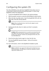
... all onscreen instructions. 36 2 System setup Configuring the system OS The Altos G540 M2 comes with the label side of the disc facing upward. Note: EasyBUILD only supports the Microsoft and Red Hat Linux operating systems. The Windows or Red Hat installation disc(s) is required to the EasyBUILD Installation guide. Improper insertion may damage both the disc and the DVD-ROM drive. 5 Press the drive Eject button again to...
... all onscreen instructions. 36 2 System setup Configuring the system OS The Altos G540 M2 comes with the label side of the disc facing upward. Note: EasyBUILD only supports the Microsoft and Red Hat Linux operating systems. The Windows or Red Hat installation disc(s) is required to the EasyBUILD Installation guide. Improper insertion may damage both the disc and the DVD-ROM drive. 5 Press the drive Eject button again to...
User Manual
Page 65
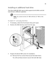
You will use these screws to secure the hard disk later. To install 3.5" a hot-plug hard drive: 1 If necessary, unlock the front bezel, then pull it open. 2 Remove the HDD dummy cover from the cage. 3 Prepare the blank HDD carrier for installation. (1) Remove the four screws that secures the blank frame. Note: You cannot mix the 3.5" HDD with the 2.5" HDD on the system. 55 Installing an additional hard drive The Altos G540 M2 HDD cage models supports both SATA2 and SAS hard drives in different capacities.
You will use these screws to secure the hard disk later. To install 3.5" a hot-plug hard drive: 1 If necessary, unlock the front bezel, then pull it open. 2 Remove the HDD dummy cover from the cage. 3 Prepare the blank HDD carrier for installation. (1) Remove the four screws that secures the blank frame. Note: You cannot mix the 3.5" HDD with the 2.5" HDD on the system. 55 Installing an additional hard drive The Altos G540 M2 HDD cage models supports both SATA2 and SAS hard drives in different capacities.

User Manual
Page 78
... replacing or installing a processor. • The CPU 1 socket must always be populated. Processor configuration guidelines The mainboard supports up all important system files. • When installing a second processor, make sure to back up to boot. • Before removing a processor, make sure it has same stepping and frequency specifications as the default processor. • Handle the processor and the HSF assembly carefully. To upgrade the default processor: 1 Perform the pre-installation instructions...
... replacing or installing a processor. • The CPU 1 socket must always be populated. Processor configuration guidelines The mainboard supports up all important system files. • When installing a second processor, make sure to back up to boot. • Before removing a processor, make sure it has same stepping and frequency specifications as the default processor. • Handle the processor and the HSF assembly carefully. To upgrade the default processor: 1 Perform the pre-installation instructions...

User Manual
Page 119
... 4-way Memory Control Sets the memory control settings. System No memory will be retested on each of the DDR3 Registered/Unbufferred DIMM slots. Independent Mirror Lock Spare Memory Frequency Sets the memory frequency. 111 Parameter Description Option Extended Memory Total size of extended memory detected during POST DIMM Group A1-A2 to F1 to delete the Yes historical memory data log. Memory Retest Select whether to F2 Status The size of memory installed on...
... 4-way Memory Control Sets the memory control settings. System No memory will be retested on each of the DDR3 Registered/Unbufferred DIMM slots. Independent Mirror Lock Spare Memory Frequency Sets the memory frequency. 111 Parameter Description Option Extended Memory Total size of extended memory detected during POST DIMM Group A1-A2 to F1 to delete the Yes historical memory data log. Memory Retest Select whether to F2 Status The size of memory installed on...
User Manual
Page 124
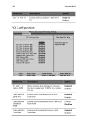
... LAN1 Enables or Disables the Onboard LAN1 Controller Controller. Enabled Disabled Onboard LAN iSCSI Boot ROM Enables or Disables the Onboard LAN iSCSI Enabled Boot ROM. Option Enabled Disabled PCI Configuration Parameter Description Option PCI Slot 1 - 5 Option ROM When enabled, this setting will initialize the device expansion ROM for Port 10. Enabled Disabled Onboard VGA Enables or Disables the Onboard VGA Controller Controller. Enabled Disabled 116 4 System BIOS Parameter VT-d for Port 10 Description Enables or Disables the VT-d for the related PCI slot.
... LAN1 Enables or Disables the Onboard LAN1 Controller Controller. Enabled Disabled Onboard LAN iSCSI Boot ROM Enables or Disables the Onboard LAN iSCSI Enabled Boot ROM. Option Enabled Disabled PCI Configuration Parameter Description Option PCI Slot 1 - 5 Option ROM When enabled, this setting will initialize the device expansion ROM for Port 10. Enabled Disabled Onboard VGA Enables or Disables the Onboard VGA Controller Controller. Enabled Disabled 116 4 System BIOS Parameter VT-d for Port 10 Description Enables or Disables the VT-d for the related PCI slot.
User Manual
Page 134
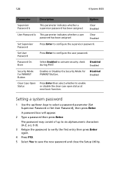
... Yes to select a password parameter (Set Supervisor Password or Set User Password), then press Enter. The password may consist of up /down keys to save the new password and close the Setup Utility. Clear Enabled User Password Is This parameter indicates whether a user password has been assigned. Disabled Enabled Clear Case Open Status Press Enter then select whether to activate security check during POST. 126 4 System BIOS Parameter Description Option Supervisor Password Is This parameter indicates...
... Yes to select a password parameter (Set Supervisor Password or Set User Password), then press Enter. The password may consist of up /down keys to save the new password and close the Setup Utility. Clear Enabled User Password Is This parameter indicates whether a user password has been assigned. Disabled Enabled Clear Case Open Status Press Enter then select whether to activate security check during POST. 126 4 System BIOS Parameter Description Option Supervisor Password Is This parameter indicates...

User Manual
Page 146
If the problem you are usually caused by an incorrect installation or configuration. 138 5 System troubleshooting Initial system startup problems Problems that occur at initial system startup are experiencing is with the software program" section on page 144. Hardware failure is problem with a specific application, see the "There is a less possible cause.
If the problem you are usually caused by an incorrect installation or configuration. 138 5 System troubleshooting Initial system startup problems Problems that occur at initial system startup are experiencing is with the software program" section on page 144. Hardware failure is problem with a specific application, see the "There is a less possible cause.
User Manual
Page 147
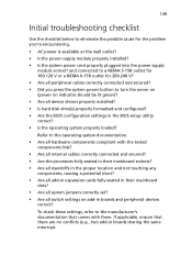
... troubleshooting checklist Use the checklist below to turn the server on (power on add-in boards and peripheral devices correct? and connected to a NEMA 5-15R outlet for 100-120 V or a NEMA 6-15R outlet for 200-240 V? • Are all switch settings on indicator should be lit green)? • Are all device drivers properly installed? • Is hard disk drive(s) properly formatted and configured? • Are the BIOS configuration settings in the BIOS setup utility...
... troubleshooting checklist Use the checklist below to turn the server on (power on add-in boards and peripheral devices correct? and connected to a NEMA 5-15R outlet for 100-120 V or a NEMA 6-15R outlet for 200-240 V? • Are all switch settings on indicator should be lit green)? • Are all device drivers properly installed? • Is hard disk drive(s) properly formatted and configured? • Are the BIOS configuration settings in the BIOS setup utility...

User Manual
Page 150
If reboot is successful, install the cards back in cares and see if the system boots. Power indicator does not light. Do the following: • Make sure the power supply module is properly installed. • Make sure the power cord is connected correctly. • Make sure that may arise during the use of them is lit up green. • Remove all add-in one at a time...
If reboot is successful, install the cards back in cares and see if the system boots. Power indicator does not light. Do the following: • Make sure the power supply module is properly installed. • Make sure the power cord is connected correctly. • Make sure that may arise during the use of them is lit up green. • Remove all add-in one at a time...
User Manual
Page 157
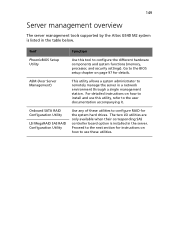
... SAS controller board option is listed in the server. 149 Server management overview The server management tools supported by the Altos G540 M2 system is installed in the table below. Onboard SATA RAID Configuration Utility LSI MegaRAID SAS RAID Configuration Utility Use any of these utilities. ASM (Acer Server Management) This utility allows a system administrator to use this tool to the user documentation accompanying it. Go to configure RAID for details. For detailed instructions on how to remotely manage the server in a network environment through a single management...
... SAS controller board option is listed in the server. 149 Server management overview The server management tools supported by the Altos G540 M2 system is installed in the table below. Onboard SATA RAID Configuration Utility LSI MegaRAID SAS RAID Configuration Utility Use any of these utilities. ASM (Acer Server Management) This utility allows a system administrator to use this tool to the user documentation accompanying it. Go to configure RAID for details. For detailed instructions on how to remotely manage the server in a network environment through a single management...
User Manual
Page 158
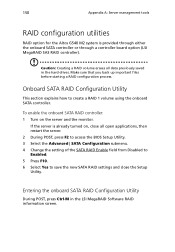
... the hard drives. Caution: Creating a RAID volume erases all open applications, then restart the server. 2 During POST, press F2 to access the BIOS Setup Utility. 3 Select the Advanced | SATA Configuration submenu. 4 Change the setting of the SATA RAID Enable field from Disabled to Enabled. 5 Press F10. 6 Select Yes to create a RAID 1 volume using the onboard SATA controller. 150 Appendix A: Server management tools RAID configuration utilities RAID option for the Altos G540 M2 system is already turned on the server and the monitor. Onboard SATA RAID Configuration Utility This section...
... the hard drives. Caution: Creating a RAID volume erases all open applications, then restart the server. 2 During POST, press F2 to access the BIOS Setup Utility. 3 Select the Advanced | SATA Configuration submenu. 4 Change the setting of the SATA RAID Enable field from Disabled to Enabled. 5 Press F10. 6 Select Yes to create a RAID 1 volume using the onboard SATA controller. 150 Appendix A: Server management tools RAID configuration utilities RAID option for the Altos G540 M2 system is already turned on the server and the monitor. Onboard SATA RAID Configuration Utility This section...
User Manual
Page 166
This appendix shows you how to set up the Altos G540 M2 server in a rack mount configuration.
This appendix shows you how to set up the Altos G540 M2 server in a rack mount configuration.
User Manual
Page 219
... menu 125 Server menu 128 System Management 129 boot-time diagnostic screen 120 boot-up sequence 133 C CMOS RAM 99 console redirection 130 D DVD-ROM drive location 10 troubleshooting 143 E easy-swap HDD cable connections 58, 63 install 58, 63 electrostatic discharge, see ESD precautions 41 environmental specifications temperature 6 expansion card I/O interface 88 install 88 F floppy disk drive replace 64 front bezel remove 44 view 9 front panel 10 H hard drive activity indicator, location 11 activity indicator, status 24 RAID configuration 150 troubleshooting 143 hardware upgrade options...
... menu 125 Server menu 128 System Management 129 boot-time diagnostic screen 120 boot-up sequence 133 C CMOS RAM 99 console redirection 130 D DVD-ROM drive location 10 troubleshooting 143 E easy-swap HDD cable connections 58, 63 install 58, 63 electrostatic discharge, see ESD precautions 41 environmental specifications temperature 6 expansion card I/O interface 88 install 88 F floppy disk drive replace 64 front bezel remove 44 view 9 front panel 10 H hard drive activity indicator, location 11 activity indicator, status 24 RAID configuration 150 troubleshooting 143 hardware upgrade options...
User Manual
Page 220
... specifications chassis 6 media storage specification 4 memory install 85 population order 79 remove 83 troubleshooting 143 monitor port 14 O Onboard SATA RAID Configuration Utility 150 operating system configure 36 support 5 P PCI bus slots BIOS settings 116 overview 88 PhoenixBIOS Setup Utility, see BIOS Setup 100 POST error pause 120 turn-on procedure 34 power boot-up problems 34 boot-up sequence 133 button, location 11 cable socket 13 indicator, location 11 indicator, status 24 troubleshooting 142 turn off 38 turn on 33 power off via hardware 38 via software 38 power supply module fault...
... specifications chassis 6 media storage specification 4 memory install 85 population order 79 remove 83 troubleshooting 143 monitor port 14 O Onboard SATA RAID Configuration Utility 150 operating system configure 36 support 5 P PCI bus slots BIOS settings 116 overview 88 PhoenixBIOS Setup Utility, see BIOS Setup 100 POST error pause 120 turn-on procedure 34 power boot-up problems 34 boot-up sequence 133 button, location 11 cable socket 13 indicator, location 11 indicator, status 24 troubleshooting 142 turn off 38 turn on 33 power off via hardware 38 via software 38 power supply module fault...

User Manual
Page 221
... fan location 15 system passwords change 127 power-on password 125 remove 127 set 126 supervisor password 125 user password 125 system reset cold boot 137 soft boot 137 system setup connect peripherals 32 install OS 36 213 pre-installation requirements 31 turn on system 33 system upgrade 5.25 inch storage device 64 ESD precautions 41 expansion card 88 hard drive 45 installation precautions 41 memory 78 post-installation instructions 42 preinstallation instructions 42 processor 70 redundant power supply module 94 T thermal grease 74 troubleshooting display problems 145 DVD-ROM drive problems...
... fan location 15 system passwords change 127 power-on password 125 remove 127 set 126 supervisor password 125 user password 125 system reset cold boot 137 soft boot 137 system setup connect peripherals 32 install OS 36 213 pre-installation requirements 31 turn on system 33 system upgrade 5.25 inch storage device 64 ESD precautions 41 expansion card 88 hard drive 45 installation precautions 41 memory 78 post-installation instructions 42 preinstallation instructions 42 processor 70 redundant power supply module 94 T thermal grease 74 troubleshooting display problems 145 DVD-ROM drive problems...


