User Manual
Page 8
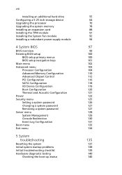
... Installing an additional hard drive Configuring a 5-25 inch storage device Upgrading the processor Upgrading the system memory Installing an expansion card Installing the TPM module Installing the System Fan module Installing a redundant power supply... System BIOS BIOS overview Entering BIOS setup BIOS setup primary menus BIOS setup navigation keys Main menu Advanced menu Processor Configuration Advanced Memory Configuration Advanced Chipset Control PCI Configuration SATA Configuration I/O Device Configuration Boot Configuration Thermal and Acoustic Configuration Power Security menu Setting a ...
... Installing an additional hard drive Configuring a 5-25 inch storage device Upgrading the processor Upgrading the system memory Installing an expansion card Installing the TPM module Installing the System Fan module Installing a redundant power supply... System BIOS BIOS overview Entering BIOS setup BIOS setup primary menus BIOS setup navigation keys Main menu Advanced menu Processor Configuration Advanced Memory Configuration Advanced Chipset Control PCI Configuration SATA Configuration I/O Device Configuration Boot Configuration Thermal and Acoustic Configuration Power Security menu Setting a ...

User Manual
Page 13
...Up to 2.93 GHz • 4.80/5.86/6.40 GT/s QPI • 4/8 MB shared cache • 800/1066/1333 DDR3 memory • Support for the following Intel® technologies:1 • Turbo Boost Technology • Hyper-Threading (HT) Technology • Virtualization...Memory • Twelve DDR3 1333 MHz ECC unbuffered/registered DIMMs (six DIMMs per processor), supporting: • Six-channel memory bus (three channels per processor) • 1 to 8 GB (subject to availability) registered DIMMs for up to 96 GB of total system memory, or 1 to 4 GB unbuffered DIMMs for up to 48 GB of the Altos G540 M2...
...Up to 2.93 GHz • 4.80/5.86/6.40 GT/s QPI • 4/8 MB shared cache • 800/1066/1333 DDR3 memory • Support for the following Intel® technologies:1 • Turbo Boost Technology • Hyper-Threading (HT) Technology • Virtualization...Memory • Twelve DDR3 1333 MHz ECC unbuffered/registered DIMMs (six DIMMs per processor), supporting: • Six-channel memory bus (three channels per processor) • 1 to 8 GB (subject to availability) registered DIMMs for up to 96 GB of total system memory, or 1 to 4 GB unbuffered DIMMs for up to 48 GB of the Altos G540 M2...

User Manual
Page 14
...® x8 slot (with four PCI Express® lanes) • One PCI (32-bit / 3.3 V) slot Video controller • Embedded graphics controller with 32 MB video memory Networking • Integrated dual-port Gigabit Ethernet supporting Intel® I/O Acceleration Technology (IOAT) • Integrated single-port 10/100 Fast Ethernet for server management and...
...® x8 slot (with four PCI Express® lanes) • One PCI (32-bit / 3.3 V) slot Video controller • Embedded graphics controller with 32 MB video memory Networking • Integrated dual-port Gigabit Ethernet supporting Intel® I/O Acceleration Technology (IOAT) • Integrated single-port 10/100 Fast Ethernet for server management and...

User Manual
Page 17
7 Hardware options Note: To purchase the any of the following hardware options, contact your local Acer representative. • Intel® Xeon® processor 5500 series: • 2.66 - 2.93 GHz with 8 MB shared cache, 6.40 GT/s QPI • 2.26 - 2.53 GHz with 8 ..., 5.86 GT/s QPI • 1.86 - 2.13 GHz with 4 MB shared cache, 4.80 GT/s QPI • 1.86 GHz with 4 MB shared cache, 4.80 GT/s QPI • Memory • Registered DDR3 1333 MHz ECC DIMMs: 1/2/4/8 GB • Unbuffered DDR3 1333 MHz ECC DIMMs: 1/2/4 GB • HDD: • 2.5" SAS (10,000 RPM) HDD: 73...
7 Hardware options Note: To purchase the any of the following hardware options, contact your local Acer representative. • Intel® Xeon® processor 5500 series: • 2.66 - 2.93 GHz with 8 MB shared cache, 6.40 GT/s QPI • 2.26 - 2.53 GHz with 8 ..., 5.86 GT/s QPI • 1.86 - 2.13 GHz with 4 MB shared cache, 4.80 GT/s QPI • 1.86 GHz with 4 MB shared cache, 4.80 GT/s QPI • Memory • Registered DDR3 1333 MHz ECC DIMMs: 1/2/4/8 GB • Unbuffered DDR3 1333 MHz ECC DIMMs: 1/2/4 GB • HDD: • 2.5" SAS (10,000 RPM) HDD: 73...

User Manual
Page 22
12 1 System tour No. This identifies a particular unit within a server group during servicing or maintenance procedures. This memory dump can later be analyzed to determine the cause of the server's CPU registers and RAM to a network server or to diskettes. Unit ...identification (UID) switch/indicator Press the ID button to issue a non-maskable interrupt. This will perform a memory dump-writing the contents of the problem. Icon 20 21 Component Description NMI switch If the system crashes or stops normal operation, press the NMI...
12 1 System tour No. This identifies a particular unit within a server group during servicing or maintenance procedures. This memory dump can later be analyzed to determine the cause of the server's CPU registers and RAM to a network server or to diskettes. Unit ...identification (UID) switch/indicator Press the ID button to issue a non-maskable interrupt. This will perform a memory dump-writing the contents of the problem. Icon 20 21 Component Description NMI switch If the system crashes or stops normal operation, press the NMI...

User Manual
Page 86
Memory Configuration Guideline Altos G540 M2 has twelve DIMM slots. Each channel has 2 sockets. For CPU1, it will be channel D,E &F. The farthest socket to DIMM C2 slots. For CPU2, it will be channel A, B &C. For all memory modes, the socket 1 in color black). If socket 1 is socket 2 (A2,B2,C2,D2,E2,F2 in each channel should... install the memory module into DIMM A1 to CPU is socket 1 (A1,B1,C1,D1,E1,F1 in color BLUE ), while the nearest one is empty, socket 2 can't ...
Memory Configuration Guideline Altos G540 M2 has twelve DIMM slots. Each channel has 2 sockets. For CPU1, it will be channel D,E &F. The farthest socket to DIMM C2 slots. For CPU2, it will be channel A, B &C. For all memory modes, the socket 1 in color black). If socket 1 is socket 2 (A2,B2,C2,D2,E2,F2 in each channel should... install the memory module into DIMM A1 to CPU is socket 1 (A1,B1,C1,D1,E1,F1 in color BLUE ), while the nearest one is empty, socket 2 can't ...

User Manual
Page 87
.... • CPU 2 - 77 (2) The DIMM D1 to function, DIMM modules must be installed following the slot sequence listed below when installing a memory module. For the system to DIMM F2 slots are enabled when a second CPU is installed on the mainboard. Independent Mode: Singel processor configuration Observe the... organization. Populate DIMM slots A1 first, followed by slots E1, F1, D2, E2, and F2. • To ensure data integrity, use only Acer-approved 240-pin, DDR3 Registered/Unbufferred DIMM ECC modules in the same colored DIMM slots. • CPU 1 - Total Capacity 1GB 2GB 3GB 4GB ...
.... • CPU 2 - 77 (2) The DIMM D1 to function, DIMM modules must be installed following the slot sequence listed below when installing a memory module. For the system to DIMM F2 slots are enabled when a second CPU is installed on the mainboard. Independent Mode: Singel processor configuration Observe the... organization. Populate DIMM slots A1 first, followed by slots E1, F1, D2, E2, and F2. • To ensure data integrity, use only Acer-approved 240-pin, DDR3 Registered/Unbufferred DIMM ECC modules in the same colored DIMM slots. • CPU 1 - Total Capacity 1GB 2GB 3GB 4GB ...

User Manual
Page 88
... 8GB 8GB 8GB 8GB Note: *Support depends on 8GB DIMM available Dual processor configuration Observe the population sequence illustrated in the table below when installing a memory module.
... 8GB 8GB 8GB 8GB Note: *Support depends on 8GB DIMM available Dual processor configuration Observe the population sequence illustrated in the table below when installing a memory module.

User Manual
Page 89
... a primary image and a copy of the primary image. A2 and B2 memory should be the same type, size and manufacturer. • Channel C has no function in this mode. • Same rule is reduced by at least one-...
... a primary image and a copy of the primary image. A2 and B2 memory should be the same type, size and manufacturer. • Channel C has no function in this mode. • Same rule is reduced by at least one-...

User Manual
Page 95
Run the BIOS setup to view the new value for total system memory and make a note of memory installed. 85 7 Observe the post-installation instructions described on page 42. The system automatically detects the amount of it.
Run the BIOS setup to view the new value for total system memory and make a note of memory installed. 85 7 Observe the post-installation instructions described on page 42. The system automatically detects the amount of it.

User Manual
Page 107
... detected by the system and you are prompted ("Run Setup" message) to be the same those found in a battery-backed nonvolatile memory called CMOS RAM. You will be bad. This memory area is not part of the system RAM which allows configuration data to make sure that you close the Setup. The...
... detected by the system and you are prompted ("Run Setup" message) to be the same those found in a battery-backed nonvolatile memory called CMOS RAM. You will be bad. This memory area is not part of the system RAM which allows configuration data to make sure that you close the Setup. The...

User Manual
Page 110
System Date Sets the date following the hour-minute-second format. 102 Main menu 4 System BIOS Parameter Description System Time Sets the system time following the weekday-month-day-year format. BIOS Version Version number of the BIOS setup utility BIOS Date Date when the BIOS setup utility was created CPU Type CPU Speed CPU Count Technical specifications for the installed processor Extended Memory Total size of extended memory detected during POST
System Date Sets the date following the hour-minute-second format. 102 Main menu 4 System BIOS Parameter Description System Time Sets the system time following the weekday-month-day-year format. BIOS Version Version number of the BIOS setup utility BIOS Date Date when the BIOS setup utility was created CPU Type CPU Speed CPU Count Technical specifications for the installed processor Extended Memory Total size of extended memory detected during POST

User Manual
Page 114
..." on the next boot-up. Enabled Disabled CPU Thermal Trip A signal that reduces the latency associated with memory reads. Enabled Disabled Processor Power Management Manages the processor power. NUMA Aware Enables or Disables the NonUniform Memory Architecture. VT allows a single platform to enable the Intel Virtualization Technology function. 106 4 System BIOS Parameter...
..." on the next boot-up. Enabled Disabled CPU Thermal Trip A signal that reduces the latency associated with memory reads. Enabled Disabled Processor Power Management Manages the processor power. NUMA Aware Enables or Disables the NonUniform Memory Architecture. VT allows a single platform to enable the Intel Virtualization Technology function. 106 4 System BIOS Parameter...

User Manual
Page 118
110 Advanced Memory Configuration 4 System BIOS Parameter System Memory Description Option Total size of system memory detected during POST
110 Advanced Memory Configuration 4 System BIOS Parameter System Memory Description Option Total size of system memory detected during POST

User Manual
Page 119
... during POST DIMM Group A1-A2 to F1 to delete the Yes historical memory data log. Independent Mirror Lock Spare Memory Frequency Sets the memory frequency. System No memory will be retested on each of the DDR3 Registered/Unbufferred DIMM slots. Auto DDR3-800 DDR3-1067 DDR3-1333 Channel Interleave Setting Sets the channel...
... during POST DIMM Group A1-A2 to F1 to delete the Yes historical memory data log. Independent Mirror Lock Spare Memory Frequency Sets the memory frequency. System No memory will be retested on each of the DDR3 Registered/Unbufferred DIMM slots. Auto DDR3-800 DDR3-1067 DDR3-1333 Channel Interleave Setting Sets the channel...

User Manual
Page 121
Enabled Disabled QPI Frequency Selection Sets the QPI Frequency Selection. Enabled Disabled Memory ECC Error Log Sets the Memory ECC Error Log. Disabled Enable Enables or Disables the Enable Yes Multimedia Multimedia Timer. No Timer 113 Parameter Description Option QPI Link Fast Mode Enables ...
Enabled Disabled QPI Frequency Selection Sets the QPI Frequency Selection. Enabled Disabled Memory ECC Error Log Sets the Memory ECC Error Log. Disabled Enable Enables or Disables the Enable Yes Multimedia Multimedia Timer. No Timer 113 Parameter Description Option QPI Link Fast Mode Enables ...

User Manual
Page 129
...open-loop thermal throttle control function when the projected memory temperature exceeds a predefined limit. Air Speed to the DIMMs Sets the speed of physical space DIMMs between Sets the distance of air flow to improve memory power management. Option Enabled Disabled 35 10 1500 0... 400 Pitch between each memory module. Temperature Chassis inlet Temperature detected at the chassis inlet. Temperature Rise Sets the ...
...open-loop thermal throttle control function when the projected memory temperature exceeds a predefined limit. Air Speed to the DIMMs Sets the speed of physical space DIMMs between Sets the distance of air flow to improve memory power management. Option Enabled Disabled 35 10 1500 0... 400 Pitch between each memory module. Temperature Chassis inlet Temperature detected at the chassis inlet. Temperature Rise Sets the ...

User Manual
Page 130
... the location 0 Altitude where the system is used. Temperature Rise Sets the temperature rise parameter 10 of a memory module to the memory modules. 1500 System Sets the altitude of physical space 400 DIMMs between each memory module. Enabled Disabled Temperature Sets the temperature hysteresis. 1 Hysteresis Temperature Sets the temperature guardband. 3 Guardband Temperature Chassis...
... the location 0 Altitude where the system is used. Temperature Rise Sets the temperature rise parameter 10 of a memory module to the memory modules. 1500 System Sets the altitude of physical space 400 DIMMs between each memory module. Enabled Disabled Temperature Sets the temperature hysteresis. 1 Hysteresis Temperature Sets the temperature guardband. 3 Guardband Temperature Chassis...

User Manual
Page 142
... setup parameters. Discards changes made in terms of resources consumption. If you choose to quit from the BIOS setup. Setup Defaults are using low-speed memory chips or other kinds of the exit options then press Enter. Saves changes made and close the BIOS setup. Parameter Exit Saving Changes Exit Discarding...
... setup parameters. Discards changes made in terms of resources consumption. If you choose to quit from the BIOS setup. Setup Defaults are using low-speed memory chips or other kinds of the exit options then press Enter. Saves changes made and close the BIOS setup. Parameter Exit Saving Changes Exit Discarding...

User Manual
Page 145
This will halt power to reset the system using one of the methods below. To do this Press Ctrl+Alt+Del Press the system power button off and then on. Perform Purpose Soft boot reset To clear the system memory and reload the operating system. Cold boot reset To clear the system memory, restart POST, and reload the operating system. 137 Resetting the system Before going through in-depth troubleshooting, attempt first to all peripherals.
This will halt power to reset the system using one of the methods below. To do this Press Ctrl+Alt+Del Press the system power button off and then on. Perform Purpose Soft boot reset To clear the system memory and reload the operating system. Cold boot reset To clear the system memory, restart POST, and reload the operating system. 137 Resetting the system Before going through in-depth troubleshooting, attempt first to all peripherals.
