
Altos R700 Chassis Subassembly
Page 7
... 17 Supplies Needed 17 Installation/Assembly Safety Instructions 18 Use Only for Intended Applications 18 Checking the Power Cord 19 Warnings and Cautions 19 Installing System Components 21 Remove the Cover 21 Remove the Processor Air Duct 22 Remove the Riser Cards 22 Remove the Fan module 23 Install the Server Board 24 Routing Cables 27 Installing Peripherals 35 Installing a PCI Card on a Riser Card 35 Installing the Riser Cards on the Server Board 36 Installing a Hard Drive 37 Installing a DVD drive/FDD or CD-ROM drive/FDD Module...
... 17 Supplies Needed 17 Installation/Assembly Safety Instructions 18 Use Only for Intended Applications 18 Checking the Power Cord 19 Warnings and Cautions 19 Installing System Components 21 Remove the Cover 21 Remove the Processor Air Duct 22 Remove the Riser Cards 22 Remove the Fan module 23 Install the Server Board 24 Routing Cables 27 Installing Peripherals 35 Installing a PCI Card on a Riser Card 35 Installing the Riser Cards on the Server Board 36 Installing a Hard Drive 37 Installing a DVD drive/FDD or CD-ROM drive/FDD Module...

Altos R700 Chassis Subassembly
Page 8
...Equipment Rack Precautions 44 4 Working Inside Your Server 47 Tools and Supplies Needed 48 Safety: Before You Remove the Cover 48 Warnings and Cautions 49 Lithium Battery Replacement 49 Replacing Components 51 Replacing a Hard Drive 51 Replacing a DVD/CD-ROM drive/FDD Module 52 Replacing a PCI Add-in Card 54 Replacing a 500 Watt Power Supply Module 56 Replacing a Power Supply Cage 57 Installing a Redundant Fan 59 Replacing the Fan Module 61 Replacing a Backplane Board 62 Replacing a Front Panel Board 63 Replacing a Server Board 64 Appendix A: Equipment Log and...
...Equipment Rack Precautions 44 4 Working Inside Your Server 47 Tools and Supplies Needed 48 Safety: Before You Remove the Cover 48 Warnings and Cautions 49 Lithium Battery Replacement 49 Replacing Components 51 Replacing a Hard Drive 51 Replacing a DVD/CD-ROM drive/FDD Module 52 Replacing a PCI Add-in Card 54 Replacing a 500 Watt Power Supply Module 56 Replacing a Power Supply Cage 57 Installing a Redundant Fan 59 Replacing the Fan Module 61 Replacing a Backplane Board 62 Replacing a Front Panel Board 63 Replacing a Server Board 64 Appendix A: Equipment Log and...

Altos R700 Chassis Subassembly
Page 10
... server chassis kit is designed to backplane board) • One Resource CD-ROM containing drivers, utilities, and product guide • Mounting screws (server board) • Front, mid, or 4-post rack mounting kit The fan module and riser cards are installed for use with one module and one blank • Two PCI riser cards for shipment, but you must remove and reinstall them when you install the server board. Your kit includes the following components: • 2U rack-mount chassis featuring: • Four hard drive...
... server chassis kit is designed to backplane board) • One Resource CD-ROM containing drivers, utilities, and product guide • Mounting screws (server board) • Front, mid, or 4-post rack mounting kit The fan module and riser cards are installed for use with one module and one blank • Two PCI riser cards for shipment, but you must remove and reinstall them when you install the server board. Your kit includes the following components: • 2U rack-mount chassis featuring: • Four hard drive...

Altos R700 Chassis Subassembly
Page 11
... difficulty removing network cables connected to the card. 3 Items You Must Purchase Separately The following components must be purchased separately: • Front bezel (optional) • Altos R700 Server Board • Minimum of one Intel® Xeon™ processor • Registered ECC DDR RAM memory DIMMs • SCSI hard disk drives (HDD) • Slimline DVD/CD-ROM drive/floppy disk drive module (optional) • PCI add-in cards • Hard drive carriers (over the four supplied) • 500 W power supply module...
... difficulty removing network cables connected to the card. 3 Items You Must Purchase Separately The following components must be purchased separately: • Front bezel (optional) • Altos R700 Server Board • Minimum of one Intel® Xeon™ processor • Registered ECC DDR RAM memory DIMMs • SCSI hard disk drives (HDD) • Slimline DVD/CD-ROM drive/floppy disk drive module (optional) • PCI add-in cards • Hard drive carriers (over the four supplied) • 500 W power supply module...
Altos R700 Chassis Subassembly
Page 14
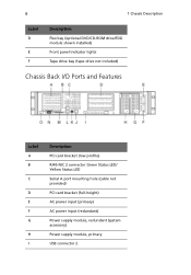
6 1 Chassis Description Label D E F Description Flex bay (optional DVD/CD-ROM drive/FDD module shown installed) Front panel indicator lights Tape drive bay (tape drive not included) Chassis Back I/O Ports and Features Label A B C D E F G H I Description PCI card bracket (low profile) RJ45 NIC 2 connector Green Status LED/ Yellow Status LED Serial A port mounting hole (cable not provided) PCI card bracket (full-height) AC power input (primary) AC power input (redundant) Power supply module, redundant (system accessory) Power supply module, primary USB connector 2
6 1 Chassis Description Label D E F Description Flex bay (optional DVD/CD-ROM drive/FDD module shown installed) Front panel indicator lights Tape drive bay (tape drive not included) Chassis Back I/O Ports and Features Label A B C D E F G H I Description PCI card bracket (low profile) RJ45 NIC 2 connector Green Status LED/ Yellow Status LED Serial A port mounting hole (cable not provided) PCI card bracket (full-height) AC power input (primary) AC power input (redundant) Power supply module, redundant (system accessory) Power supply module, primary USB connector 2

Altos R700 Chassis Subassembly
Page 15
7 Label J K L M N O Description RJ45 serial port PS/2 mouse/keyboard connector RJ45 NIC 1 connector SCSI channel A connector (If available) Video connector USB connector 1 Note: 480 Watt redundant power supply shown. Label A B Description NIC 2 activity LED Power button Your power supply may be different. Front Panel Controls and Indicators Shown with optional DVD/CD-ROM drive/floppy disk drive installed.
7 Label J K L M N O Description RJ45 serial port PS/2 mouse/keyboard connector RJ45 NIC 1 connector SCSI channel A connector (If available) Video connector USB connector 1 Note: 480 Watt redundant power supply shown. Label A B Description NIC 2 activity LED Power button Your power supply may be different. Front Panel Controls and Indicators Shown with optional DVD/CD-ROM drive/floppy disk drive installed.

Altos R700 Chassis Subassembly
Page 17
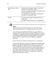
... ACPI compliant operating systems. Reboots and initializes the system. Blinking amber light (Note 1) indicates the system is in a degraded condition. The baseboard ID LED is connected. 9 Control Button Functions Power/Sleep button Reset button NMI button ID button Toggles the system power on /off . Blinking green light (Note 4) indicates the system is operating normally. Continuous green light indicates activity between the system and the network to it (other than 5 V standby power). Pressing the...
... ACPI compliant operating systems. Reboots and initializes the system. Blinking amber light (Note 1) indicates the system is in a degraded condition. The baseboard ID LED is connected. 9 Control Button Functions Power/Sleep button Reset button NMI button ID button Toggles the system power on /off . Blinking green light (Note 4) indicates the system is operating normally. Continuous green light indicates activity between the system and the network to it (other than 5 V standby power). Pressing the...
Altos R700 Chassis Subassembly
Page 18
... until the BIOS clears it is possible that the System Status LED is powered down normally, it . The Power LED sleep indication is maintained on or blinking, the Green LED is off due to the Baseboard Management Controller (BMC), or the system board must send a Set Fault Indication command to a failure or configuration change that prevents the BIOS from running. No light indicates ID button is depressed. When the Amber LED is not powered down without...
... until the BIOS clears it is possible that the System Status LED is powered down normally, it . The Power LED sleep indication is maintained on or blinking, the Green LED is off due to the Baseboard Management Controller (BMC), or the system board must send a Set Fault Indication command to a failure or configuration change that prevents the BIOS from running. No light indicates ID button is depressed. When the Amber LED is not powered down without...

Altos R700 Chassis Subassembly
Page 20
... module, or a seventh hot swappable SCSI HDD. The system fans are hot swappable. The power supply operates within the following voltage ranges and is turned off. The drive fault LED becomes a continuous amber light. For information on installation, see "Installing a DVD drive/FDD or CDROM drive/FDD Module" on page 39. 500 Watt Redundant Power Supply The power supply consists of sources. System Cooling The chassis includes four 60-mm non-hot-swappable system fans for cooling the processor(s), hard drives...
... module, or a seventh hot swappable SCSI HDD. The system fans are hot swappable. The power supply operates within the following voltage ranges and is turned off. The drive fault LED becomes a continuous amber light. For information on installation, see "Installing a DVD drive/FDD or CDROM drive/FDD Module" on page 39. 500 Watt Redundant Power Supply The power supply consists of sources. System Cooling The chassis includes four 60-mm non-hot-swappable system fans for cooling the processor(s), hard drives...

Altos R700 Chassis Subassembly
Page 21
... chassis also includes a preinstalled intrusion switch for cooling. The power supply contains a single fan for the top access cover that can be opened. The bezel is now locked and cannot be opened , the switch, located on the front panel board, transmits a signal to the system's peripherals and control panel, install the optional front bezel, which provides a key lock. The bezel is now unlocked and can be monitored by server management software...
... chassis also includes a preinstalled intrusion switch for cooling. The power supply contains a single fan for the top access cover that can be opened. The bezel is now locked and cannot be opened , the switch, located on the front panel board, transmits a signal to the system's peripherals and control panel, install the optional front bezel, which provides a key lock. The bezel is now unlocked and can be monitored by server management software...

Altos R700 Chassis Subassembly
Page 27
... of the chassis. Only a technically qualified person should integrate and configure the server. The power supply cords are not the exact type required. Warnings and Cautions These warnings and cautions apply whenever you remove the chassis cover to access components inside the server. Then unplug all peripheral devices connected to the server. 2. 19 Checking the Power Cord Warning: Do not attempt to modify or use in your region. Turn off the server by an...
... of the chassis. Only a technically qualified person should integrate and configure the server. The power supply cords are not the exact type required. Warnings and Cautions These warnings and cautions apply whenever you remove the chassis cover to access components inside the server. Then unplug all peripheral devices connected to the server. 2. 19 Checking the Power Cord Warning: Do not attempt to modify or use in your region. Turn off the server by an...

Altos R700 Chassis Subassembly
Page 36
... clarity) Server Board To backplane power connector from power supply To server board primary power connector from power supply Floppy/FP/IDE flex circuit cable from server board to backplane SCSI cable from server board to backplane USB ribbon cable from front panel board to server board Ribbon cable from front panel board to backplane Fan module to server board fan connectors (2) To server board auxiliary signal connector from power supply To server board auxiliary power connector from power supply Serial cable from server board to knockout on back of chassis Connect Power Cables 1 Verify...
... clarity) Server Board To backplane power connector from power supply To server board primary power connector from power supply Floppy/FP/IDE flex circuit cable from server board to backplane SCSI cable from server board to backplane USB ribbon cable from front panel board to server board Ribbon cable from front panel board to backplane Fan module to server board fan connectors (2) To server board auxiliary signal connector from power supply To server board auxiliary power connector from power supply Serial cable from server board to knockout on back of chassis Connect Power Cables 1 Verify...

Altos R700 Chassis Subassembly
Page 42
... to route the SCSI cable after the full length PCI riser card is installed. 5 Ensure that the front panel cable is connected to the front panel board, routed over USB cable to the backplane, and connected to the SCSI connector on the server board. All cables from the power supply should route through the notch in the bottom of the power supply air baffle, to the connector on the side of the processor duct, through...
... to route the SCSI cable after the full length PCI riser card is installed. 5 Ensure that the front panel cable is connected to the front panel board, routed over USB cable to the backplane, and connected to the SCSI connector on the server board. All cables from the power supply should route through the notch in the bottom of the power supply air baffle, to the connector on the side of the processor duct, through...

Altos R700 Chassis Subassembly
Page 43
...) PCI add-in cards or three LP cards (an LP card must be purchased separately. Installing a PCI Card on a Riser Card The riser card nearest the chassis sidewall (see "Installing the Riser Cards on the Server Board" on page 36. If you may encounter difficulty removing network cables connected to "Installing the Riser Cards on the Server Board" on page 36, A) supports three full-length, full-height PCI add-in cards. PCI add-in cards, hard disk drives, a DVD/CD-ROM drive/floppy disk drive, and a tape drive. Note...
...) PCI add-in cards or three LP cards (an LP card must be purchased separately. Installing a PCI Card on a Riser Card The riser card nearest the chassis sidewall (see "Installing the Riser Cards on the Server Board" on page 36. If you may encounter difficulty removing network cables connected to "Installing the Riser Cards on the Server Board" on page 36, A) supports three full-length, full-height PCI add-in cards. PCI add-in cards, hard disk drives, a DVD/CD-ROM drive/floppy disk drive, and a tape drive. Note...

Altos R700 Chassis Subassembly
Page 52
... fluctuations in temperature can be labeled as controlling power to the entire unit, not just to 20 amperes of any other devices installed in the rack. You must be configured for front-mount, mid-mount, or 4-post racks. 44 3 Installing the System in a Rack Your Altos R700 chassis comes equipped with a rack mount kit that are responsible for installing an AC power disconnect for the entire rack unit. Equipment Rack Precautions Caution...
... fluctuations in temperature can be labeled as controlling power to the entire unit, not just to 20 amperes of any other devices installed in the rack. You must be configured for front-mount, mid-mount, or 4-post racks. 44 3 Installing the System in a Rack Your Altos R700 chassis comes equipped with a rack mount kit that are responsible for installing an AC power disconnect for the entire rack unit. Equipment Rack Precautions Caution...

Altos R700 Chassis Subassembly
Page 68
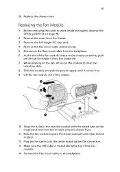
... the fan module onto the chassis floor. 14 Slide the fan module toward the chassis sidewall until it has locked in place. 15 Plug the fan cables into the server board system fan connectors. 16 Make sure the USB cable is routed along the top of the fan module. 17 Connect the flex circuit cable to the backplane. 18 Install the flex circuit cable retention clip. 19 Install the full-height PCI riser card.
... the fan module onto the chassis floor. 14 Slide the fan module toward the chassis sidewall until it has locked in place. 15 Plug the fan cables into the server board system fan connectors. 16 Make sure the USB cable is routed along the top of the fan module. 17 Connect the flex circuit cable to the backplane. 18 Install the flex circuit cable retention clip. 19 Install the full-height PCI riser card.
Altos R700 Chassis Subassembly
Page 69
... fan module with the raised tabs on the chassis and lower the fan module onto the chassis floor. 11 Slide the fan module toward the chassis sidewall until it has locked in place. 12 Plug the fan cables into the server board system fan connectors. 13 Make sure the USB cable is routed along the top of the fan module. 14 Connect the flex circuit cable to the backplane. 61 20 Replace the chassis cover...
... fan module with the raised tabs on the chassis and lower the fan module onto the chassis floor. 11 Slide the fan module toward the chassis sidewall until it has locked in place. 12 Plug the fan cables into the server board system fan connectors. 13 Make sure the USB cable is routed along the top of the fan module. 14 Connect the flex circuit cable to the backplane. 61 20 Replace the chassis cover...

Altos R700 Chassis Subassembly
Page 71
63 9 Install and tighten the thumscrew. Replacing a Front Panel Board 1 Before removing the cover to the board. 11 Install the fan module. 12 Install the full-height PCI riser card. 13 Install all hard drives and peripherals in their original paths to minimize airflow blockage and cooling problems. 10 Connect all cables to work inside the system, observe the safety guidelines on page 48. 2 Remove the cover from the chassis. Caution: Carefully route cables in their bays. 14 Install the chassis cover.
63 9 Install and tighten the thumscrew. Replacing a Front Panel Board 1 Before removing the cover to the board. 11 Install the fan module. 12 Install the full-height PCI riser card. 13 Install all hard drives and peripherals in their original paths to minimize airflow blockage and cooling problems. 10 Connect all cables to work inside the system, observe the safety guidelines on page 48. 2 Remove the cover from the chassis. Caution: Carefully route cables in their bays. 14 Install the chassis cover.
Altos R700 Chassis Subassembly
Page 76
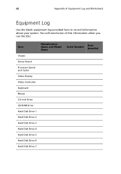
Item Manufacturer Name and Model Name Chassis Server Board Processor Speed and Cache Video Display Video Controller Keyboard Mouse 3.5-inch Drive CD-ROM Drive Hard Disk Drive 1 Hard Disk Drive 2 Hard Disk Drive 3 Hard Disk Drive 4 Hard Disk Drive 5 Hard Disk Drive 6 Hard Disk Drive 7 Serial Number Date Installed 68 Appendix A: Equipment Log and Worksheets Equipment Log Use the blank equipment log provided here to record information about your system. You will need some of this information when you run the SSU.
Item Manufacturer Name and Model Name Chassis Server Board Processor Speed and Cache Video Display Video Controller Keyboard Mouse 3.5-inch Drive CD-ROM Drive Hard Disk Drive 1 Hard Disk Drive 2 Hard Disk Drive 3 Hard Disk Drive 4 Hard Disk Drive 5 Hard Disk Drive 6 Hard Disk Drive 7 Serial Number Date Installed 68 Appendix A: Equipment Log and Worksheets Equipment Log Use the blank equipment log provided here to record information about your system. You will need some of this information when you run the SSU.
Altos R700 Chassis Subassembly
Page 78
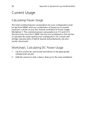
... combined power consumption for each board and device in the appropriate voltage level column. 2 Add the current in this section to the next worksheet. Worksheet, Calculating DC Power Usage 1 List the current for your configuration must be more then 150W. Use the two worksheets in each column, then go to calculate the total used by your vendor documents. For current and voltage requirements of...
... combined power consumption for each board and device in the appropriate voltage level column. 2 Add the current in this section to the next worksheet. Worksheet, Calculating DC Power Usage 1 List the current for your configuration must be more then 150W. Use the two worksheets in each column, then go to calculate the total used by your vendor documents. For current and voltage requirements of...


