
Altos R720 User's Guide
Page 7
... panel 8 Rear panel 13 Internal components 16 System boards 17 Mainboard 17 Backplane and mid-plane board 19 System diagnostic LEDs 22 System jumpers 23 2 System setup 25 Setting up the system 27 Pre-installation requirements 27 Connecting peripherals 28 Turning on the system 29 Power-on problems 30 Configuring the system OS 31 Turning off the system 32 3 System upgrade 33 Installation precautions 35 ESD precautions 35 Pre-installation instructions 35 Post-installation instructions 36 Opening the server...
... panel 8 Rear panel 13 Internal components 16 System boards 17 Mainboard 17 Backplane and mid-plane board 19 System diagnostic LEDs 22 System jumpers 23 2 System setup 25 Setting up the system 27 Pre-installation requirements 27 Connecting peripherals 28 Turning on the system 29 Power-on problems 30 Configuring the system OS 31 Turning off the system 32 3 System upgrade 33 Installation precautions 35 ESD precautions 35 Pre-installation instructions 35 Post-installation instructions 36 Opening the server...

Altos R720 User's Guide
Page 9
ix First steps checklist 136 Hardware diagnostic testing 137 Verifying proper operation of key system lights 137 Specific problems and corrective actions 138 Error beep codes 146 BIOS POST error beep codes 146 ARMC/3 module error beep codes 148 Diagnostic POST code LEDs 149 Appendix A: Acer Altos R720 rack installation guide Setting up the system rack System rack installation Vertical mounting hole pattern Installing the system into the rack Appendix B: SAS hardware RAID configuration Configuring the integrated SAS hardware RAID 155 157 159 160 161 169 171 Index 173
ix First steps checklist 136 Hardware diagnostic testing 137 Verifying proper operation of key system lights 137 Specific problems and corrective actions 138 Error beep codes 146 BIOS POST error beep codes 146 ARMC/3 module error beep codes 148 Diagnostic POST code LEDs 149 Appendix A: Acer Altos R720 rack installation guide Setting up the system rack System rack installation Vertical mounting hole pattern Installing the system into the rack Appendix B: SAS hardware RAID configuration Configuring the integrated SAS hardware RAID 155 157 159 160 161 169 171 Index 173

Altos R720 User's Guide
Page 14
... an upgrade option. Note: After installing the RAID activation key and RAID cache DIMM, the system BIOS setup allows you to improve fault tolerance by enhance by protecting data in the RAID cache in the event of power failure. For detailed installation instructions, see "To install the RAID BBU" section on page 91. Networking • Intel 82563EB Gigabit controller with dual ports • Supports Intel I/O Acceleration Technology PCI I/O • Low profile riser slot •...
... an upgrade option. Note: After installing the RAID activation key and RAID cache DIMM, the system BIOS setup allows you to improve fault tolerance by enhance by protecting data in the RAID cache in the event of power failure. For detailed installation instructions, see "To install the RAID BBU" section on page 91. Networking • Intel 82563EB Gigabit controller with dual ports • Supports Intel I/O Acceleration Technology PCI I/O • Low profile riser slot •...
Altos R720 User's Guide
Page 23
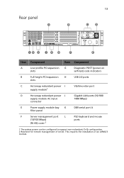
...This requires the installation of server. 13 Rear panel Item Component Item Component A Low profile PCI expansion G Diagnostic POST (power-on slots self-test) code indicators B Full height PCI expansion H USB 2.0 ports slots C Hot-swap redundant power I supply module1 VGA/monitor port D Hot-swap redundant power J supply module AC input connector Gigabit LAN ports (10/100/ 1000 Mbps) E Power supply module bay K DB9 serial port A filler panel F Server management port L PS2 keyboard and mouse (10/100 Mbps) ports (RJ-45) cover 2 1 The system power can be configured...
...This requires the installation of server. 13 Rear panel Item Component Item Component A Low profile PCI expansion G Diagnostic POST (power-on slots self-test) code indicators B Full height PCI expansion H USB 2.0 ports slots C Hot-swap redundant power I supply module1 VGA/monitor port D Hot-swap redundant power J supply module AC input connector Gigabit LAN ports (10/100/ 1000 Mbps) E Power supply module bay K DB9 serial port A filler panel F Server management port L PS2 keyboard and mouse (10/100 Mbps) ports (RJ-45) cover 2 1 The system power can be configured...
Altos R720 User's Guide
Page 24
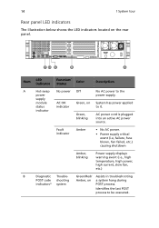
... Description A Hot-swap No power Off No AC power to be executed. Fault indicator Amber • No AC power. • Power supply critical event (i.e, failure, fuse blown, fan failed, etc.) causing shutdown Amber, blinking Power supply displays warning event (i.e., high temperature, high power, high current, slow fan, etc.) B Diagnostic Trouble- Green/Red/ Assists in troubleshooting POST code shooting Amber, on System has power applied status indicator to it. indicator Green, AC power cord is plugged blinking into an active AC power source. supply module AC...
... Description A Hot-swap No power Off No AC power to be executed. Fault indicator Amber • No AC power. • Power supply critical event (i.e, failure, fuse blown, fan failed, etc.) causing shutdown Amber, blinking Power supply displays warning event (i.e., high temperature, high power, high current, slow fan, etc.) B Diagnostic Trouble- Green/Red/ Assists in troubleshooting POST code shooting Amber, on System has power applied status indicator to it. indicator Green, AC power cord is plugged blinking into an active AC power source. supply module AC...
Altos R720 User's Guide
Page 28
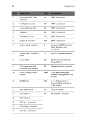
...) port M Serial B configuration jumper N DIMM slots O Intel 5000P MCH P CPU socket 1 Q CPU socket 2 R CPU fan 1 connector S CPU voltage regulator T CPU fan 2 connector Item Description CC SATA 0 connector DD SATA 1 connector EE SATA 2 connector FF SATA 3 connector GG SATA 4 connector HH SATA 5 connector II Integrated SATA hardware RAID activation key connector JJ ARMC/3 module connector KK System recovery settings jumper block LL Chassis intrusion connector MM 3-pin IPMB (Intelligent Platform Management Bus) header NN 4-in LCP (Link Control Protocol...
...) port M Serial B configuration jumper N DIMM slots O Intel 5000P MCH P CPU socket 1 Q CPU socket 2 R CPU fan 1 connector S CPU voltage regulator T CPU fan 2 connector Item Description CC SATA 0 connector DD SATA 1 connector EE SATA 2 connector FF SATA 3 connector GG SATA 4 connector HH SATA 5 connector II Integrated SATA hardware RAID activation key connector JJ ARMC/3 module connector KK System recovery settings jumper block LL Chassis intrusion connector MM 3-pin IPMB (Intelligent Platform Management Bus) header NN 4-in LCP (Link Control Protocol...

Altos R720 User's Guide
Page 77
... pre-installation instructions described on page 35. 2 Lower the PCI riser assembly (A), aligning the three hooks on the back edge of the riser assembly with the matching slots on the rear of the chassis (B). 3 Press down on the assembly until the three hooks on the rear of the riser assembly engage the chassis back panel slots. 4 Connect the cables to the installed PCI card. 5 Observe the post-installation instructions...
... pre-installation instructions described on page 35. 2 Lower the PCI riser assembly (A), aligning the three hooks on the back edge of the riser assembly with the matching slots on the rear of the chassis (B). 3 Press down on the assembly until the three hooks on the rear of the riser assembly engage the chassis back panel slots. 4 Connect the cables to the installed PCI card. 5 Observe the post-installation instructions...

Altos R720 User's Guide
Page 91
... the system by pressing the power button, and unplug the AC power cord from the system or wall outlet. 81 Installing and removing a power supply The server has two hot-swap power supply module bays on the rear panel that you are no serviceable parts inside the module. WARNING! To reduce the risk of personal injury from electric shock hazards, do not open the power supply modules. Electrostatic discharge can also consider...
... the system by pressing the power button, and unplug the AC power cord from the system or wall outlet. 81 Installing and removing a power supply The server has two hot-swap power supply module bays on the rear panel that you are no serviceable parts inside the module. WARNING! To reduce the risk of personal injury from electric shock hazards, do not open the power supply modules. Electrostatic discharge can also consider...
Altos R720 User's Guide
Page 101
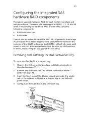
... push down to drives, maintaining the integrity of the DIMM by using the following components: • RAID activation key • RAID cache There is restored, data can be safely written to detach the activation key. If power to the storage I/O processor drops below specifications, the RAID BBU maintains the contents of the disk array. 91 Configuring the integrated SAS hardware RAID components The system supports hardware RAID through the SAS mid-plane and backplane board.
... push down to drives, maintaining the integrity of the DIMM by using the following components: • RAID activation key • RAID cache There is restored, data can be safely written to detach the activation key. If power to the storage I/O processor drops below specifications, the RAID BBU maintains the contents of the disk array. 91 Configuring the integrated SAS hardware RAID components The system supports hardware RAID through the SAS mid-plane and backplane board.

Altos R720 User's Guide
Page 118
... effective memory installed in the server. Current Configuration Displays the current memory configuration. If you install additional mamory, the system automatically adjusts this parameter to access the Configure Memory RAS and Performance submenu. The memory size is automatically detected by BIOS during the POST. 108 4 BIOS setup Memory The Memory submenu displays the total amount of memory installed, the number of onboard memory. Parameter Description Total Memory Indicates the total amount of memory modules installed, and the current memory configuration.
... effective memory installed in the server. Current Configuration Displays the current memory configuration. If you install additional mamory, the system automatically adjusts this parameter to access the Configure Memory RAS and Performance submenu. The memory size is automatically detected by BIOS during the POST. 108 4 BIOS setup Memory The Memory submenu displays the total amount of memory installed, the number of onboard memory. Parameter Description Total Memory Indicates the total amount of memory modules installed, and the current memory configuration.

Altos R720 User's Guide
Page 124
... I/O port 60/64h emulation support. Parameter USB Controller Legacy USB Support Port 60/64 Emulation Device Reset Timeout Description Option Enables or disables the USB controller. Enabled Disabled Enables or disables the support for USB devices. 114 4 BIOS setup USB Confguration The USB Configuration submenu allows you specify settings for legacy USB devices. This parameter is enabled for complete USB keyboard legacy support for the USB mass storage device after the start unit command. 20 Sec 10 Sec 30 Sec 40 Sec Enabled Disabled Select the number of seconds POST...
... I/O port 60/64h emulation support. Parameter USB Controller Legacy USB Support Port 60/64 Emulation Device Reset Timeout Description Option Enables or disables the USB controller. Enabled Disabled Enables or disables the support for USB devices. 114 4 BIOS setup USB Confguration The USB Configuration submenu allows you specify settings for legacy USB devices. This parameter is enabled for complete USB keyboard legacy support for the USB mass storage device after the start unit command. 20 Sec 10 Sec 30 Sec 40 Sec Enabled Disabled Select the number of seconds POST...

Altos R720 User's Guide
Page 130
... controlled via system management interface. After setting the password, the system automatically sets the chosen password parameter to Not Installed. 120 4 BIOS setup Parameter Front Panel Lockout Description When Enabled, the front panel power and reset buttons will appear. 2 Type a password then press Enter. To remove the User password 1 Use the up to seven alphanumeric characters (A-Z, a-z, 0-9). 3 Retype the password to highlight a password parameter (Set Administrator Password or Set User Password) then press Enter. The password may consist of up /down keys...
... controlled via system management interface. After setting the password, the system automatically sets the chosen password parameter to Not Installed. 120 4 BIOS setup Parameter Front Panel Lockout Description When Enabled, the front panel power and reset buttons will appear. 2 Type a password then press Enter. To remove the User password 1 Use the up to seven alphanumeric characters (A-Z, a-z, 0-9). 3 Retype the password to highlight a password parameter (Set Administrator Password or Set User Password) then press Enter. The password may consist of up /down keys...

Altos R720 User's Guide
Page 132
... to Reset, the system will reset the system if BIOS does not complete the POST before the FRB-2 (Fault Resilient Booting) timer expires. Stay Off Last State Reset Deletes all events in the System Event Log. When Enabled, the BMC (Baseboard Management Controller) will turn on AC Power Loss Clear System Event Log FRB-2 Enable O/S Boot Watchdog Timer Console Redirection System Information Description Option Defines the mode of operation if a power loss occurs. When set to...
... to Reset, the system will reset the system if BIOS does not complete the POST before the FRB-2 (Fault Resilient Booting) timer expires. Stay Off Last State Reset Deletes all events in the System Event Log. When Enabled, the BMC (Baseboard Management Controller) will turn on AC Power Loss Clear System Event Log FRB-2 Enable O/S Boot Watchdog Timer Console Redirection System Information Description Option Defines the mode of operation if a power loss occurs. When set to...
Altos R720 User's Guide
Page 145
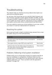
... or local Acer representative for assistance. Hardware failure is problem with a specific software application, see "There is a less frequent cause. Firmware upgrades include updates for components you have installed in -depth troubleshooting, attempt first to resolve your server problems on . Cold boot reset. Turn the system power off and then on your own, contact your system, such as video drivers, network drivers and SAS drivers. Press Ctrl+Alt+Del Reset button Power button Problems following initial system installation Problems that...
... or local Acer representative for assistance. Hardware failure is problem with a specific software application, see "There is a less frequent cause. Firmware upgrades include updates for components you have installed in -depth troubleshooting, attempt first to resolve your server problems on . Cold boot reset. Turn the system power off and then on your own, contact your system, such as video drivers, network drivers and SAS drivers. Press Ctrl+Alt+Del Reset button Power button Problems following initial system installation Problems that...
Altos R720 User's Guide
Page 146
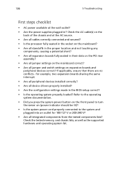
... switch settings on (power indicator should be lit)? • Is the system power cord properly connected to turn the server on expansion boards and peripheral devices correct? for 100-127 V or 200-240 V? • Are all device drivers properly installed? • Are the configuration settings made in ? Check the tested memory, and chassis lists, as well as the supported hardware and operating system list. Refer to the operating system documentation. • Did you press the system power button...
... switch settings on (power indicator should be lit)? • Is the system power cord properly connected to turn the server on expansion boards and peripheral devices correct? for 100-127 V or 200-240 V? • Are all device drivers properly installed? • Are the configuration settings made in ? Check the tested memory, and chassis lists, as well as the supported hardware and operating system list. Refer to the operating system documentation. • Did you press the system power button...

Altos R720 User's Guide
Page 147
... video display monitor). 4 If the operating system normally loads from the hard disk drive, make sure there is checked, its source. Failure to do so can cause permanent damage to the system and/ or the peripheral device. 1 Turn off the system and any external peripheral devices. Turn on page 139. 137 Hardware diagnostic testing This section provides a more detailed approach to identifying a hardware problem and locating its activity light should turn...
... video display monitor). 4 If the operating system normally loads from the hard disk drive, make sure there is checked, its source. Failure to do so can cause permanent damage to the system and/ or the peripheral device. 1 Turn off the system and any external peripheral devices. Turn on page 139. 137 Hardware diagnostic testing This section provides a more detailed approach to identifying a hardware problem and locating its activity light should turn...

Altos R720 User's Guide
Page 153
... onboard video controller enabled in the BIOS setup? • Remove all cables are loaded. No characters appear on the system, contact your vendor about the defective software. Refer to the software installation and operation documentation for the system. Change the PCI interrrupt settings. Do the following : • Is the keyboard functioning? If successful, add the cards back in and turned on setting up and using . • Make sure all expansion cards and...
... onboard video controller enabled in the BIOS setup? • Remove all cables are loaded. No characters appear on the system, contact your vendor about the defective software. Refer to the software installation and operation documentation for the system. Change the PCI interrrupt settings. Do the following : • Is the keyboard functioning? If successful, add the cards back in and turned on setting up and using . • Make sure all expansion cards and...
Altos R720 User's Guide
Page 183
... User password 119 Server Management 121 Console Redirection 123 System Information 124 BIOS setup 99 entering 100 C configuring the system OS 31 CPU installing 75 removing 74 CPU air dam removing 44 CPU air duct installing 43 removing 42, 43 D DIMM module installation guidelines 77 DIMMs installing 78 removing 79 F FDD in converted HDD bay installing 56 removing 59 front bezel 7 installing 38 removing 38 front panel 7, 8 control buttons 9 LED indicators 10 front panel control button function 9 H hardware RAID components 91 HDD installing 49 removing 48 hot-plug power supply...
... User password 119 Server Management 121 Console Redirection 123 System Information 124 BIOS setup 99 entering 100 C configuring the system OS 31 CPU installing 75 removing 74 CPU air dam removing 44 CPU air duct installing 43 removing 42, 43 D DIMM module installation guidelines 77 DIMMs installing 78 removing 79 F FDD in converted HDD bay installing 56 removing 59 front bezel 7 installing 38 removing 38 front panel 7, 8 control buttons 9 LED indicators 10 front panel control button function 9 H hardware RAID components 91 HDD installing 49 removing 48 hot-plug power supply...
Altos R720 User's Guide
Page 184
...P PCI card installing 70 removing 69 PCI riser assembly installing 67 removing 65 PCI riser board installing 68 removing 68 peripherals 28 power cord 29 power supply installing 82 removing 83 processor upgrade guidelines 74 R rack installing 161 rack installation 155 mounting pattern 160 precautions 157 RAID activation key installing 92 removing 91 RAID BBU installing 95 removing 94 RAID cache removing 92 RAID configuration 169 SAS hardware RAID utility assign hot spare 172 create RAID Volume 171 using SAS hardware RAID utility 171 rear panel 13 LED indicators 14 removing ARMC/3 module 84 CPU...
...P PCI card installing 70 removing 69 PCI riser assembly installing 67 removing 65 PCI riser board installing 68 removing 68 peripherals 28 power cord 29 power supply installing 82 removing 83 processor upgrade guidelines 74 R rack installing 161 rack installation 155 mounting pattern 160 precautions 157 RAID activation key installing 92 removing 91 RAID BBU installing 95 removing 94 RAID cache removing 92 RAID configuration 169 SAS hardware RAID utility assign hot spare 172 create RAID Volume 171 using SAS hardware RAID utility 171 rear panel 13 LED indicators 14 removing ARMC/3 module 84 CPU...

Altos R720 User's Guide
Page 185
... I/O 4 power supply 5 processor 3 SAS mid-plane board 4 serial ATA port 4 system fan 5 system boards 17 backplane 19 SAS backplane board 19 mainboard 17 mid-plane board SAS mid-plane board 21 system diagnostic LEDs 22 system fan replacing 72 system features 3 system jumpers 23 system memory reconfiguring 80 system tour 1 system upgrade 33 ESD precautions 35 installation precautions 35 post-installation instructions 36 preinstallation instructions 35 T tape drive installing 60 top cover installing 41 removing 41 troubleshooting 133 confirming loading of the OS 138 hardware diagnostic testing...
... I/O 4 power supply 5 processor 3 SAS mid-plane board 4 serial ATA port 4 system fan 5 system boards 17 backplane 19 SAS backplane board 19 mainboard 17 mid-plane board SAS mid-plane board 21 system diagnostic LEDs 22 system fan replacing 72 system features 3 system jumpers 23 system memory reconfiguring 80 system tour 1 system upgrade 33 ESD precautions 35 installation precautions 35 post-installation instructions 36 preinstallation instructions 35 T tape drive installing 60 top cover installing 41 removing 41 troubleshooting 133 confirming loading of the OS 138 hardware diagnostic testing...


