
Altos R720 User's Guide
Page 7
... internal structure 7 Front bezel 7 Front panel 8 Rear panel 13 Internal components 16 System boards 17 Mainboard 17 Backplane and mid-plane board 19 System diagnostic LEDs 22 System jumpers 23 2 System setup 25 Setting up the system 27 Pre-installation requirements 27 Connecting peripherals 28 Turning on the system 29 Power...
... internal structure 7 Front bezel 7 Front panel 8 Rear panel 13 Internal components 16 System boards 17 Mainboard 17 Backplane and mid-plane board 19 System diagnostic LEDs 22 System jumpers 23 2 System setup 25 Setting up the system 27 Pre-installation requirements 27 Connecting peripherals 28 Turning on the system 29 Power...

Altos R720 User's Guide
Page 9
ix First steps checklist 136 Hardware diagnostic testing 137 Verifying proper operation of key system lights 137 Specific problems and corrective actions 138 Error beep codes 146 BIOS POST error beep codes 146 ARMC/3 module error beep codes 148 Diagnostic POST code LEDs 149 Appendix A: Acer Altos R720 rack installation guide Setting up the system rack System rack installation Vertical mounting hole pattern Installing the system into the rack Appendix B: SAS hardware RAID configuration Configuring the integrated SAS hardware RAID 155 157 159 160 161 169 171 Index 173
ix First steps checklist 136 Hardware diagnostic testing 137 Verifying proper operation of key system lights 137 Specific problems and corrective actions 138 Error beep codes 146 BIOS POST error beep codes 146 ARMC/3 module error beep codes 148 Diagnostic POST code LEDs 149 Appendix A: Acer Altos R720 rack installation guide Setting up the system rack System rack installation Vertical mounting hole pattern Installing the system into the rack Appendix B: SAS hardware RAID configuration Configuring the integrated SAS hardware RAID 155 157 159 160 161 169 171 Index 173
Altos R720 User's Guide
Page 17
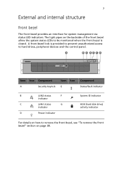
... on how to remove the front bezel, see "To remove the front bezel" section on the backside of the front bezel allow the system status LEDs to be monitored when the front bezel is provided to prevent unauthorized access to hard drives, peripheral devices and the control panel. A front bezel lock...
... on how to remove the front bezel, see "To remove the front bezel" section on the backside of the front bezel allow the system status LEDs to be monitored when the front bezel is provided to prevent unauthorized access to hard drives, peripheral devices and the control panel. A front bezel lock...

Altos R720 User's Guide
Page 19
Item NMI button Reset button Power button System ID button Hot-plug HDD carrier latch Function Puts the server in a halt-state for diagnostic purposes. Press to reset the system. Press to turn the system power on and off . Press to turn the system ID LED on and off . 9 Front panel control button functions Below table lists the functions of the front panel control buttons. Press to release the carrier lever.
Item NMI button Reset button Power button System ID button Hot-plug HDD carrier latch Function Puts the server in a halt-state for diagnostic purposes. Press to reset the system. Press to turn the system power on and off . Press to turn the system ID LED on and off . 9 Front panel control button functions Below table lists the functions of the front panel control buttons. Press to release the carrier lever.
Altos R720 User's Guide
Page 20
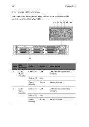
Network access Link between system and network. Network access 10 1 System tour Front panel LED indicators The illustration below shows the LED indicators available on Link status indicator Green, off Idle Green, blinking Active Description Link between system and network. Item LED indicator Color Status A LAN2 Green, on Link status indicator Green, off Idle Green, blinking Active B LAN1 Green, on the control panel and hot-plug HDD.
Network access Link between system and network. Network access 10 1 System tour Front panel LED indicators The illustration below shows the LED indicators available on Link status indicator Green, off Idle Green, blinking Active Description Link between system and network. Item LED indicator Color Status A LAN2 Green, on Link status indicator Green, off Idle Green, blinking Active B LAN1 Green, on the control panel and hot-plug HDD.
Altos R720 User's Guide
Page 21
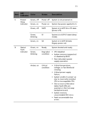
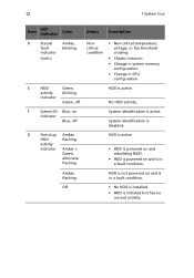
... power up due to incorrectly installed CPU or incompatible CPU. • One or more of the drive status fault LEDs are asserted on System has power applied to it. Green, on ). 11 Item LED indicator Color Status Description C Power/ Green, off Power off ). D Status/ Green, on . Green, S1 blinking System is not...
... power up due to incorrectly installed CPU or incompatible CPU. • One or more of the drive status fault LEDs are asserted on System has power applied to it. Green, on ). 11 Item LED indicator Color Status Description C Power/ Green, off Power off ). D Status/ Green, on . Green, S1 blinking System is not...
Altos R720 User's Guide
Page 22
... HDD is in CPU configuration. E HDD Green, activity blinking indicator Green, off System identification is initiated but has no current activity. 12 1 System tour Item LED indicator Color Status Description D Status/ Amber, Non- • Non-critical temperature, fault blinking critical voltage, or fan threshold indicator condition crossing. (cont.) • Chassis intrusion...
... HDD is in CPU configuration. E HDD Green, activity blinking indicator Green, off System identification is initiated but has no current activity. 12 1 System tour Item LED indicator Color Status Description D Status/ Amber, Non- • Non-critical temperature, fault blinking critical voltage, or fan threshold indicator condition crossing. (cont.) • Chassis intrusion...
Altos R720 User's Guide
Page 24
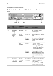
... last POST process to the power power supply. Green/Red/ Assists in troubleshooting POST code shooting Amber, on the rear panel. Item LED indicator Function/ Status Color Description A Hot-swap No power Off No AC power to be executed. Fault indicator Amber • No...(i.e., high temperature, high power, high current, slow fan, etc.) B Diagnostic Trouble- 14 1 System tour Rear panel LED indicators The illustration below shows the LED indicators located on a system hang during indicators* system POST process. supply module AC OK Green, on System has power ...
... last POST process to the power power supply. Green/Red/ Assists in troubleshooting POST code shooting Amber, on the rear panel. Item LED indicator Function/ Status Color Description A Hot-swap No power Off No AC power to be executed. Fault indicator Amber • No...(i.e., high temperature, high power, high current, slow fan, etc.) B Diagnostic Trouble- 14 1 System tour Rear panel LED indicators The illustration below shows the LED indicators located on a system hang during indicators* system POST process. supply module AC OK Green, on System has power ...
Altos R720 User's Guide
Page 25
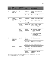
... blower failure. • Non-critical blower, voltage, and temperature failure. Blue, off System identification is detected. blinking Critical condition Amber, on page 149. 15 Item LED indicator Function/ Status Color Description C System ID ID indicator Blue, on System booted and ready. D System Ready Green, on System identification is active.
... blower failure. • Non-critical blower, voltage, and temperature failure. Blue, off System identification is detected. blinking Critical condition Amber, on page 149. 15 Item LED indicator Function/ Status Color Description C System ID ID indicator Blue, on System booted and ready. D System Ready Green, on System identification is active.
Altos R720 User's Guide
Page 32
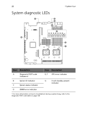
22 System diagnostic LEDs 1 System tour Item Description A Diagnostic POST code indicators* B System ID indicator C System status indicator D DIMM error indicator Item Description E, F CPU error indicator G 5-volt standby present indicator * For more information on how to troubleshoot during a system hang, refer to the Diagnostic POST code table on page 149.
22 System diagnostic LEDs 1 System tour Item Description A Diagnostic POST code indicators* B System ID indicator C System status indicator D DIMM error indicator Item Description E, F CPU error indicator G 5-volt standby present indicator * For more information on how to troubleshoot during a system hang, refer to the Diagnostic POST code table on page 149.
Altos R720 User's Guide
Page 39
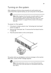
...bezel. See "Unlocking the front bezel" section on the system: 1 If the bezel is locked, unlock it. Refer to "Front panel LED indicators" on or boot after pressing the power button, go to warm up and displays a welcome message on the control panel. See ...on the monitor. Note: If the system does not turn on page 10 for 30 seconds or until the Status/fault LED on the control panel stops blinking before turning on the system. After that you have properly set up the system and ...AC power cord, allow system to the next section for the possible causes of the Status/ fault LED.
...bezel. See "Unlocking the front bezel" section on the system: 1 If the bezel is locked, unlock it. Refer to "Front panel LED indicators" on or boot after pressing the power button, go to warm up and displays a welcome message on the control panel. See ...on the monitor. Note: If the system does not turn on page 10 for 30 seconds or until the Status/fault LED on the control panel stops blinking before turning on the system. After that you have properly set up the system and ...AC power cord, allow system to the next section for the possible causes of the Status/ fault LED.
Altos R720 User's Guide
Page 58
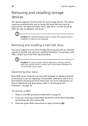
... ESD precautions described on page 35. 2 If you are removing a failed HDD, determine which drive has failed by checking the drive status LED. 3 Press the green HDD carrier latch to the server. Caution! An optional floppy drive, tape drive, or sixth hot-plug HDD can...Acer representative. 48 3 System upgrade Removing and installing storage devices The system supports 3.5-inch and 5.25-inch storage devices. The system comes pre-installed with an optional sixth drive board). If you are replacing a failed HDD, determine which drive has failed by checking the drive status LED...
... ESD precautions described on page 35. 2 If you are removing a failed HDD, determine which drive has failed by checking the drive status LED. 3 Press the green HDD carrier latch to the server. Caution! An optional floppy drive, tape drive, or sixth hot-plug HDD can...Acer representative. 48 3 System upgrade Removing and installing storage devices The system supports 3.5-inch and 5.25-inch storage devices. The system comes pre-installed with an optional sixth drive board). If you are replacing a failed HDD, determine which drive has failed by checking the drive status LED...
Altos R720 User's Guide
Page 82
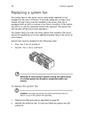
... fans on the server can be individually replaced or hotswapped in the event of a failed system fan should be replaced. If the system fan LED is equipped with only three system fans installed. Fan 2, fan 4, and fan 5 • Second - Hot-swap operations should be completed within... one minute. The system fan LED remains off during normal operation. To ensure proper system cooling, the replacement of failure. To provide adequate cooling in the chassis, at least 3 fans...
... fans on the server can be individually replaced or hotswapped in the event of a failed system fan should be replaced. If the system fan LED is equipped with only three system fans installed. Fan 2, fan 4, and fan 5 • Second - Hot-swap operations should be completed within... one minute. The system fan LED remains off during normal operation. To ensure proper system cooling, the replacement of failure. To provide adequate cooling in the chassis, at least 3 fans...
Altos R720 User's Guide
Page 92
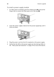
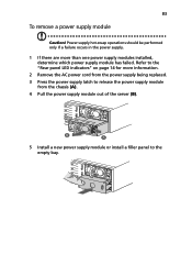
82 3 System upgrade To install a power supply module 1 If a filler panel is installed, press the release lever (A) and use the finger hole to the "Rear panel LED indicators" on the power supply are functioning. Refer to remove the filler panel out of the bay (B). 2 Insert the power supply module into the power supply bay until it locks into place. 3 Plug the power cord into the DC receptacle on the power supply. 4 Verify that the LED on page 14 for more information.
82 3 System upgrade To install a power supply module 1 If a filler panel is installed, press the release lever (A) and use the finger hole to the "Rear panel LED indicators" on the power supply are functioning. Refer to remove the filler panel out of the bay (B). 2 Insert the power supply module into the power supply bay until it locks into place. 3 Plug the power cord into the DC receptacle on the power supply. 4 Verify that the LED on page 14 for more information.
Altos R720 User's Guide
Page 93
... power supply module out of the server (B). 5 Install a new power supply module or install a filler panel to the empty bay. Refer to the "Rear panel LED indicators" on page 14 for more than one power supply modules installed, determine which power supply module has failed. 83 To remove a power supply module...
... power supply module out of the server (B). 5 Install a new power supply module or install a filler panel to the empty bay. Refer to the "Rear panel LED indicators" on page 14 for more than one power supply modules installed, determine which power supply module has failed. 83 To remove a power supply module...
Altos R720 User's Guide
Page 159
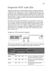
...the possible POST codes that may be displayed on the Diagnostic POST code LEDs during the POST process, the diagnostic LEDs can be used to identify the last POST process to the diagnostic POST code LEDs found on initialization of the mainboard. As each bit in troubleshooting a ...system hang during system initialization. To assist in the lower nibble is started, BIOS will be executed. Diagnostic LED Decoder Checkpoint code G=Green, R=Red, A=Amber MSB LSB Description Host Processor 0x10h OFF OFF OFF R Power-on the rear of the host ...
...the possible POST codes that may be displayed on the Diagnostic POST code LEDs during the POST process, the diagnostic LEDs can be used to identify the last POST process to the diagnostic POST code LEDs found on initialization of the mainboard. As each bit in troubleshooting a ...system hang during system initialization. To assist in the lower nibble is started, BIOS will be executed. Diagnostic LED Decoder Checkpoint code G=Green, R=Red, A=Amber MSB LSB Description Host Processor 0x10h OFF OFF OFF R Power-on the rear of the host ...
Altos R720 User's Guide
Page 160
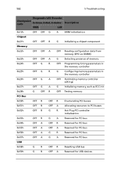
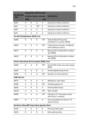
150 5 Troubleshooting Diagnostic LED Decoder Checkpoint code G=Green, R=Red, A=Amber MSB LSB Description 0x13h OFF OFF G A SMM initialization Chipset 0x21h OFF OFF R G Initializing a chipset component Memory 0x22h OFF OFF A ...
150 5 Troubleshooting Diagnostic LED Decoder Checkpoint code G=Green, R=Red, A=Amber MSB LSB Description 0x13h OFF OFF G A SMM initialization Chipset 0x21h OFF OFF R G Initializing a chipset component Memory 0x22h OFF OFF A ...
Altos R720 User's Guide
Page 161
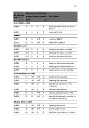
151 Diagnostic LED Decoder Checkpoint code G=Green, R=Red, A=Amber MSB LSB Description ATA / ATAPI / SATA 0x5Ah G R G R Resetting PATA / SATA bus and all devices 0x5Bh G R G A Reserved for ATA SMBUS ...
151 Diagnostic LED Decoder Checkpoint code G=Green, R=Red, A=Amber MSB LSB Description ATA / ATAPI / SATA 0x5Ah G R G R Resetting PATA / SATA bus and all devices 0x5Bh G R G A Reserved for ATA SMBUS ...
Altos R720 User's Guide
Page 162
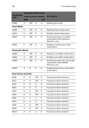
152 5 Troubleshooting Diagnostic LED Decoder Checkpoint code G=Green, R=Red, A=Amber MSB LSB Description 0x9Bh A OFF G A Enabling the mouse Fixed Media 0xB0h R OFF R R Resetting fixed media device 0xB1h R OFF R A Disabling ...
152 5 Troubleshooting Diagnostic LED Decoder Checkpoint code G=Green, R=Red, A=Amber MSB LSB Description 0x9Bh A OFF G A Enabling the mouse Fixed Media 0xB0h R OFF R R Resetting fixed media device 0xB1h R OFF R A Disabling ...
Altos R720 User's Guide
Page 163
153 Diagnostic LED Decoder Checkpoint code G=Green, R=Red, A=Amber MSB LSB Description 0xDB A R G A Trying boot device selection 0xDC A A OFF R Trying boot device selection 0xDE A A G R Trying boot device selection ...
153 Diagnostic LED Decoder Checkpoint code G=Green, R=Red, A=Amber MSB LSB Description 0xDB A R G A Trying boot device selection 0xDC A A OFF R Trying boot device selection 0xDE A A G R Trying boot device selection ...