
Altos R720 User's Guide
Page 7
... iv Important safety instructions v 1 System tour 1 Features summary 3 External and internal structure 7 Front bezel 7 Front panel 8 Rear panel 13 Internal components 16 System boards 17 Mainboard 17 Backplane and mid-plane board 19 System diagnostic LEDs 22 System jumpers 23 2 System setup 25 Setting up the system 27 Pre-installation requirements...
... iv Important safety instructions v 1 System tour 1 Features summary 3 External and internal structure 7 Front bezel 7 Front panel 8 Rear panel 13 Internal components 16 System boards 17 Mainboard 17 Backplane and mid-plane board 19 System diagnostic LEDs 22 System jumpers 23 2 System setup 25 Setting up the system 27 Pre-installation requirements...
Altos R720 User's Guide
Page 27
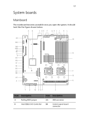
17 System boards Mainboard The mainboard becomes accessible once you open the system. It should look like the figure shown below. Item Description A Rolling BIOS jumper B Intel ESB2-E I/O Controller Item Description AA USB connector BB Control panel board connector
17 System boards Mainboard The mainboard becomes accessible once you open the system. It should look like the figure shown below. Item Description A Rolling BIOS jumper B Intel ESB2-E I/O Controller Item Description AA USB connector BB Control panel board connector
Altos R720 User's Guide
Page 40
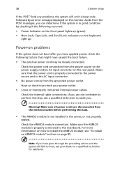
..." section on the monitor. Make sure all power cords are not confident to perform this task. • The ARMC/3 module is properly connected to the mainboard. 30 2 System setup If the POST finds any problems, the system will emit a beep code followed by checking if the following factors that the power...
..." section on the monitor. Make sure all power cords are not confident to perform this task. • The ARMC/3 module is properly connected to the mainboard. 30 2 System setup If the POST finds any problems, the system will emit a beep code followed by checking if the following factors that the power...
Altos R720 User's Guide
Page 57
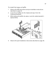
47 To install the large air baffle 1 Observe the ESD precautions and pre-installation instructions described on page 35. 2 Lower the air baffle into the chassis and snap it into the mainboard standoff. 3 While setting the baffle into place, route the cables beneath it appropriately. 4 Observe the post-installation instructions described on page 36.
47 To install the large air baffle 1 Observe the ESD precautions and pre-installation instructions described on page 35. 2 Lower the air baffle into the chassis and snap it into the mainboard standoff. 3 While setting the baffle into place, route the cables beneath it appropriately. 4 Observe the post-installation instructions described on page 36.
Altos R720 User's Guide
Page 84
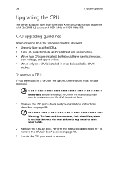
Warning! Perform the instructions described in CPU 1 socket. Important: Before removing a CPU from the mainboard, make sure to remove. NEVER touch the heat sink with any metal or with 2 x 2 MB L2 cache and 1066 MHz or 1333 MHz FSB. CPU ... installing CPUs the following must be removed. The heat sink becomes very hot when the system is installed, it must be observed: • Use only Acer-qualified CPUs. • Each CPU socket include a CPU and heat sink combination. • When two CPUs are replacing a CPU on page 35. 74 3 System upgrade...
Warning! Perform the instructions described in CPU 1 socket. Important: Before removing a CPU from the mainboard, make sure to remove. NEVER touch the heat sink with any metal or with 2 x 2 MB L2 cache and 1066 MHz or 1333 MHz FSB. CPU ... installing CPUs the following must be removed. The heat sink becomes very hot when the system is installed, it must be observed: • Use only Acer-qualified CPUs. • Each CPU socket include a CPU and heat sink combination. • When two CPUs are replacing a CPU on page 35. 74 3 System upgrade...
Altos R720 User's Guide
Page 88
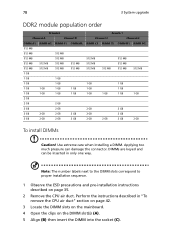
Applying too much pressure can be inserted in "To remove the CPU air duct" section on page 42. 3 Locate the DIMM slots on the mainboard. 4 Open the clips on page 35. 2 Remove the CPU air duct. Perform the instructions described in only one way. Note: The number labels next to ...
Applying too much pressure can be inserted in "To remove the CPU air duct" section on page 42. 3 Locate the DIMM slots on the mainboard. 4 Open the clips on page 35. 2 Remove the CPU air duct. Perform the instructions described in only one way. Note: The number labels next to ...
Altos R720 User's Guide
Page 89
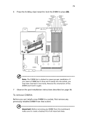
... a backup file of the DIMM and insert it incorrectly. Reverse the orientation of all important data. Important: Before removing any previously installed DIMM from the mainboard, make sure to ensure proper installation.
... a backup file of the DIMM and insert it incorrectly. Reverse the orientation of all important data. Important: Before removing any previously installed DIMM from the mainboard, make sure to ensure proper installation.
Altos R720 User's Guide
Page 94
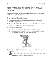
... module. 84 3 System upgrade Removing and installing an ARMC/3 module The optional ARMC/3 module provides server management firmware and functionality to remove it from the mainboard, then keep the standoffs for later NIC module installation. 4 Hold the module both by the finger grip loop and by the opposite corner (A). To remove...
... module. 84 3 System upgrade Removing and installing an ARMC/3 module The optional ARMC/3 module provides server management firmware and functionality to remove it from the mainboard, then keep the standoffs for later NIC module installation. 4 Hold the module both by the finger grip loop and by the opposite corner (A). To remove...
Altos R720 User's Guide
Page 96
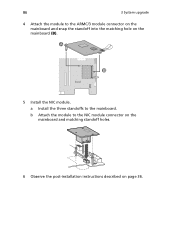
a Install the three standoffs to the ARMC/3 module connector on the mainboard and snap the standoff into the matching hole on page 36. 86 3 System upgrade 4 Attach the module to the mainboard. b Attach the module to the NIC module connector on the mainboard and matching standoff holes. 6 Observe the post-installation instructions described on the mainboard (B). 5 Install the NIC module.
a Install the three standoffs to the ARMC/3 module connector on the mainboard and snap the standoff into the matching hole on page 36. 86 3 System upgrade 4 Attach the module to the mainboard. b Attach the module to the NIC module connector on the mainboard and matching standoff holes. 6 Observe the post-installation instructions described on the mainboard (B). 5 Install the NIC module.
Altos R720 User's Guide
Page 146
...available at the AC source. • Are all cables correctly connected and secured? • Is the processor fully seated in the socket on the mainboard? • Are all standoffs in the proper location and not touching any components, causing a potential short? • Are all expansion boards fully... seated in their slots on the PCI riser assembly? • Are all jumper settings on the mainboard correct? • Are all jumper and switch settings on (power indicator should be lit)? • Is the system power cord properly connected to...
...available at the AC source. • Are all cables correctly connected and secured? • Is the processor fully seated in the socket on the mainboard? • Are all standoffs in the proper location and not touching any components, causing a potential short? • Are all expansion boards fully... seated in their slots on the PCI riser assembly? • Are all jumper settings on the mainboard correct? • Are all jumper and switch settings on (power indicator should be lit)? • Is the system power cord properly connected to...
Altos R720 User's Guide
Page 148
... problem. Specific problems and corrective actions The following : • Make sure the power button on the control panel is turned on the bottom of the mainboard and cause a short. Do the following contains specific problems that the wall outlet has power. Possible solutions are installed only below mounting holes. If successful...
... problem. Specific problems and corrective actions The following : • Make sure the power button on the control panel is turned on the bottom of the mainboard and cause a short. Do the following contains specific problems that the wall outlet has power. Possible solutions are installed only below mounting holes. If successful...
Altos R720 User's Guide
Page 154
...; Make sure the memory modules comply with the system requirements. • Make sure the memory modules have failed. This information is fully seated in the mainboard connector. 3 Reboot the system for help. System cooling fan do not appear, the video display monitor or video controller may have been populated according to...
...; Make sure the memory modules comply with the system requirements. • Make sure the memory modules have failed. This information is fully seated in the mainboard connector. 3 Reboot the system for help. System cooling fan do not appear, the video display monitor or video controller may have been populated according to...
Altos R720 User's Guide
Page 157
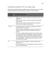
Consult your dealer or local Acer representative for assistance. • If beep codes are generated even when all expansion cards are absent, consult your system manufacturer's technical support. • Check for a ... table lists the possible beep codes thay may be faulty. If beep codes are not generated when all PCI cards are absent, one of the mainboard, the board may occur while using the system and is followed by solutions to the system requirements. • Indicates a fatal error. Number of beeps 1, 2, or...
Consult your dealer or local Acer representative for assistance. • If beep codes are generated even when all expansion cards are absent, consult your system manufacturer's technical support. • Check for a ... table lists the possible beep codes thay may be faulty. If beep codes are not generated when all PCI cards are absent, one of the mainboard, the board may occur while using the system and is followed by solutions to the system requirements. • Indicates a fatal error. Number of beeps 1, 2, or...
Altos R720 User's Guide
Page 159
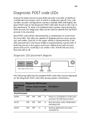
... process, the diagnostic LEDs can be used to identify the last POST process to the diagnostic POST code LEDs found on the rear of the mainboard. If both bits are set in the upper and lower nibbles then both bits are clear, then the LED is started, BIOS will be executed...
... process, the diagnostic LEDs can be used to identify the last POST process to the diagnostic POST code LEDs found on the rear of the mainboard. If both bits are set in the upper and lower nibbles then both bits are clear, then the LED is started, BIOS will be executed...

Altos R720 User's Guide
Page 185
175 OS 6 PCI I/O 4 power supply 5 processor 3 SAS mid-plane board 4 serial ATA port 4 system fan 5 system boards 17 backplane 19 SAS backplane board 19 mainboard 17 mid-plane board SAS mid-plane board 21 system diagnostic LEDs 22 system fan replacing 72 system features 3 system jumpers 23 system memory reconfiguring ...
175 OS 6 PCI I/O 4 power supply 5 processor 3 SAS mid-plane board 4 serial ATA port 4 system fan 5 system boards 17 backplane 19 SAS backplane board 19 mainboard 17 mid-plane board SAS mid-plane board 21 system diagnostic LEDs 22 system fan replacing 72 system features 3 system jumpers 23 system memory reconfiguring ...