Altos R720 User's Guide
Page 8
... the CPU 74 CPU upgrading guidelines 74 Upgrading the system memory 77 Memory module installation guidelines 77 DDR2 module population order 78 Installing and removing a power supply 81 Removing and installing an ARMC/3 module 84 Removing and installing the SAS mid-plane board 87 Removing and installing the SAS/SATA backplane board...
... the CPU 74 CPU upgrading guidelines 74 Upgrading the system memory 77 Memory module installation guidelines 77 DDR2 module population order 78 Installing and removing a power supply 81 Removing and installing an ARMC/3 module 84 Removing and installing the SAS mid-plane board 87 Removing and installing the SAS/SATA backplane board...
Altos R720 User's Guide
Page 15
... DDR SDRAM Baseboard Management Controller • Integrated BMC • IPMI (Intelligent Platform Management Interface) 2.0 compliant • Supports ARMC/3 (Acer Remote Management Card/3) (optional) Power supply • Supports one to two 750-watts hot-swap (1+1) redundant power supply modules with dual AC line cord System fan • Supports one to six hot-swap redundant system fans...
... DDR SDRAM Baseboard Management Controller • Integrated BMC • IPMI (Intelligent Platform Management Interface) 2.0 compliant • Supports ARMC/3 (Acer Remote Management Card/3) (optional) Power supply • Supports one to two 750-watts hot-swap (1+1) redundant power supply modules with dual AC line cord System fan • Supports one to six hot-swap redundant system fans...
Altos R720 User's Guide
Page 21
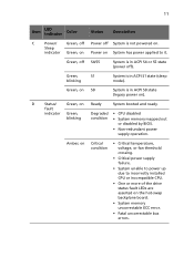
... error. • Fatal uncorrectable bus errors. Green, on S0 System is in ACPI S0 state (legacy power on Critical condition • Critical temperature, voltage, or fan threshold crossing. • Critical power supply failure. • System unable to power up due to it. Amber, on ). fault indicator Green, Degraded • CPU disabled blinking condition •...
... error. • Fatal uncorrectable bus errors. Green, on S0 System is in ACPI S0 state (legacy power on Critical condition • Critical temperature, voltage, or fan threshold crossing. • Critical power supply failure. • System unable to power up due to it. Amber, on ). fault indicator Green, Degraded • CPU disabled blinking condition •...
Altos R720 User's Guide
Page 23
... B Full height PCI expansion H USB 2.0 ports slots C Hot-swap redundant power I supply module1 VGA/monitor port D Hot-swap redundant power J supply module AC input connector Gigabit LAN ports (10/100/ 1000 Mbps) E Power supply module bay K DB9 serial port A filler panel F Server management port L... PS2 keyboard and mouse (10/100 Mbps) ports (RJ-45) cover 2 1 The system power can be configured to support non-redundant (1+0) configuration. ...
... B Full height PCI expansion H USB 2.0 ports slots C Hot-swap redundant power I supply module1 VGA/monitor port D Hot-swap redundant power J supply module AC input connector Gigabit LAN ports (10/100/ 1000 Mbps) E Power supply module bay K DB9 serial port A filler panel F Server management port L... PS2 keyboard and mouse (10/100 Mbps) ports (RJ-45) cover 2 1 The system power can be configured to support non-redundant (1+0) configuration. ...
Altos R720 User's Guide
Page 24
... hang during indicators* system POST process. Identifies the last POST process to the power power supply. indicator Green, AC power cord is plugged blinking into an active AC power source. 14 1 System tour Rear panel LED indicators The illustration below shows the...on the rear panel. Fault indicator Amber • No AC power. • Power supply critical event (i.e, failure, fuse blown, fan failed, etc.) causing shutdown Amber, blinking Power supply displays warning event (i.e., high temperature, high power, high current, slow fan, etc.) B Diagnostic Trouble-
... hang during indicators* system POST process. Identifies the last POST process to the power power supply. indicator Green, AC power cord is plugged blinking into an active AC power source. 14 1 System tour Rear panel LED indicators The illustration below shows the...on the rear panel. Fault indicator Amber • No AC power. • Power supply critical event (i.e, failure, fuse blown, fan failed, etc.) causing shutdown Amber, blinking Power supply displays warning event (i.e., high temperature, high power, high current, slow fan, etc.) B Diagnostic Trouble-
Altos R720 User's Guide
Page 25
Blue, off System identification is detected. Noncritical condition Amber, blinking • Redundant power supply or blower failure. • Non-critical blower, voltage, and temperature failure. E LAN port Speed Green/ 10 Mbps connection indicators... condition Amber, on System identification is active. 15 Item LED indicator Function/ Status Color Description C System ID ID indicator Blue, on Critical power supply, blower, voltage, or temperature failure. Green, Off No network connection. Green, Blinking Transmit or receive activity. * For more information on how...
Blue, off System identification is detected. Noncritical condition Amber, blinking • Redundant power supply or blower failure. • Non-critical blower, voltage, and temperature failure. E LAN port Speed Green/ 10 Mbps connection indicators... condition Amber, on System identification is active. 15 Item LED indicator Function/ Status Color Description C System ID ID indicator Blue, on Critical power supply, blower, voltage, or temperature failure. Green, Off No network connection. Green, Blinking Transmit or receive activity. * For more information on how...
Altos R720 User's Guide
Page 29
19 Item Description Item Description U Bridge board connector V IDE optical drive connector W +12 V CPU power connector X AC power connector Y Battery Z Power supply signal connector * Reserved for remote management of an ARMC/3 module. Backplane and mid-plane board SAS/SATA backplane board Front view Item Description A Optical drive connector B USB connector Item Description C Control panel connector D SAS/SATA connectors This requires installation of server.
19 Item Description Item Description U Bridge board connector V IDE optical drive connector W +12 V CPU power connector X AC power connector Y Battery Z Power supply signal connector * Reserved for remote management of an ARMC/3 module. Backplane and mid-plane board SAS/SATA backplane board Front view Item Description A Optical drive connector B USB connector Item Description C Control panel connector D SAS/SATA connectors This requires installation of server.
Altos R720 User's Guide
Page 40
...The ARMC/3 module is not installed in good condition by an error message displayed on the rear panel. For more information on how to the power supply module AC input connector on the monitor. Aside from the POST messages, you can determine if the system is in the server, or not...If you . Make sure that might have gone through the preceding actions and the system still fails to boot, ask your power outlet. • Loose or improperly connected internal power cables. Make sure the ARMC/3 module is properly connected to the mainboard. 30 2 System setup If the POST finds any ...
...The ARMC/3 module is not installed in good condition by an error message displayed on the rear panel. For more information on how to the power supply module AC input connector on the monitor. Aside from the POST messages, you can determine if the system is in the server, or not...If you . Make sure that might have gone through the preceding actions and the system still fails to boot, ask your power outlet. • Loose or improperly connected internal power cables. Make sure the ARMC/3 module is properly connected to the mainboard. 30 2 System setup If the POST finds any ...

Altos R720 User's Guide
Page 53
Do not pinch or unplug cables that may be flush with the top of the installed air duct should touch the front fan module and the top of the power supply. The front edge of the air duct should be near or under the air duct. 3 Observe the post-installation instructions described on page 35. 2 Place the CPU air duct over the two processor sockets. Caution! 43 To install the CPU air duct: 1 Observe the ESD precautions and pre-installation instructions described on page 36.
Do not pinch or unplug cables that may be flush with the top of the installed air duct should touch the front fan module and the top of the power supply. The front edge of the air duct should be near or under the air duct. 3 Observe the post-installation instructions described on page 35. 2 Place the CPU air duct over the two processor sockets. Caution! 43 To install the CPU air duct: 1 Observe the ESD precautions and pre-installation instructions described on page 36.
Altos R720 User's Guide
Page 55
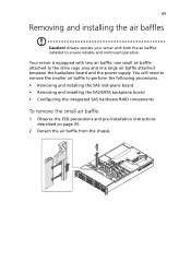
... two air baffle, one small air baffle attached to the drive cage area and one large air baffle attached between the backplane board and the power supply. You will need to remove the smaller air baffle to ensure reliable and continued operation. Your server is equipped with both the air baffles installed...
... two air baffle, one small air baffle attached to the drive cage area and one large air baffle attached between the backplane board and the power supply. You will need to remove the smaller air baffle to ensure reliable and continued operation. Your server is equipped with both the air baffles installed...

Altos R720 User's Guide
Page 91
... a single power supply module installed. 81 Installing and removing a power supply The server has two hot-swap power supply module bays on . The system ships out with two power supplies installed. Electrostatic discharge can also consider wearing protective gloves. The power supply is powered on the rear...Exceeding five minutes might cause the system to continue running even if one power supply installed, before handling a power supply module. Caution! Make sure that accept hot-swap redundant power supply modules. To reduce the risk of personal injury or damage to the equipment...
... a single power supply module installed. 81 Installing and removing a power supply The server has two hot-swap power supply module bays on . The system ships out with two power supplies installed. Electrostatic discharge can also consider wearing protective gloves. The power supply is powered on the rear...Exceeding five minutes might cause the system to continue running even if one power supply installed, before handling a power supply module. Caution! Make sure that accept hot-swap redundant power supply modules. To reduce the risk of personal injury or damage to the equipment...
Altos R720 User's Guide
Page 92
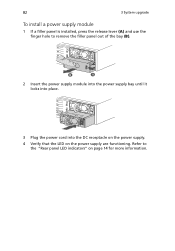
Refer to remove the filler panel out of the bay (B). 2 Insert the power supply module into the power supply bay until it locks into place. 3 Plug the power cord into the DC receptacle on the power supply. 4 Verify that the LED on page 14 for more information. 82 3 System upgrade To install a power supply module 1 If a filler panel is installed, press the release lever (A) and use the finger hole to the "Rear panel LED indicators" on the power supply are functioning.
Refer to remove the filler panel out of the bay (B). 2 Insert the power supply module into the power supply bay until it locks into place. 3 Plug the power cord into the DC receptacle on the power supply. 4 Verify that the LED on page 14 for more information. 82 3 System upgrade To install a power supply module 1 If a filler panel is installed, press the release lever (A) and use the finger hole to the "Rear panel LED indicators" on the power supply are functioning.
Altos R720 User's Guide
Page 93
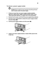
... should be performed only if a failure occurs in the power supply. 1 If there are more information. 2 Remove the AC power cord from the power supply being replaced. 3 Press the power supply latch to release the power supply module from the chassis (A). 4 Pull the power supply module out of the server (B). 5 Install a new power supply module or install a filler panel to the "Rear panel...
... should be performed only if a failure occurs in the power supply. 1 If there are more information. 2 Remove the AC power cord from the power supply being replaced. 3 Press the power supply latch to release the power supply module from the chassis (A). 4 Pull the power supply module out of the server (B). 5 Install a new power supply module or install a filler panel to the "Rear panel...

Altos R720 User's Guide
Page 106
96 3 System upgrade 6 Engage the hooks on the back of the battery into the matching chassis tabs, then slide it toward the power supply to lock into place. 7 Connect the power cable between the BBU and the mid-plane board. 8 Replace the air baffles and CPU air duct. 9 Observe the post-installation instructions described on page 36.
96 3 System upgrade 6 Engage the hooks on the back of the battery into the matching chassis tabs, then slide it toward the power supply to lock into place. 7 Connect the power cable between the BBU and the mid-plane board. 8 Replace the air baffles and CPU air duct. 9 Observe the post-installation instructions described on page 36.
Altos R720 User's Guide
Page 146
... drivers properly installed? • Are the configuration settings made in ? Refer to the operating system documentation. • Did you press the system power button on the front panel to the system and plugged into an outlet for example, two expansion boards sharing the same interrupt. • Are ...the tested components lists? Check the AC cable(s) on (power indicator should be lit)? • Is the system power cord properly connected to turn the server on the back of the chassis and at the wall outlet? • Are the power supplies plugged in the BIOS setup correct? • Is the...
... drivers properly installed? • Are the configuration settings made in ? Refer to the operating system documentation. • Did you press the system power button on the front panel to the system and plugged into an outlet for example, two expansion boards sharing the same interrupt. • Are ...the tested components lists? Check the AC cable(s) on (power indicator should be lit)? • Is the system power cord properly connected to turn the server on the back of the chassis and at the wall outlet? • Are the power supplies plugged in the BIOS setup correct? • Is the...

Altos R720 User's Guide
Page 147
...peripheral devices. Failure to do so can cause permanent damage to the system. Disconnect each of their maximum ranges (see the documentation supplied with your video display monitor and keyboard are correctly connected to the system and/ or the peripheral device. 1 Turn off the system... on briefly. Check if the HDD activity indicator lights briefly? As each mass storage device installed in the optical drive. 5 If the power indicator does light, attempt to at least two thirds of device from the system, turn on the system. Caution! Before disconnecting any external...
...peripheral devices. Failure to do so can cause permanent damage to the system. Disconnect each of their maximum ranges (see the documentation supplied with your video display monitor and keyboard are correctly connected to the system and/ or the peripheral device. 1 Turn off the system... on briefly. Check if the HDD activity indicator lights briefly? As each mass storage device installed in the optical drive. 5 If the power indicator does light, attempt to at least two thirds of device from the system, turn on the system. Caution! Before disconnecting any external...
Altos R720 User's Guide
Page 183
... removing 38 front panel 7, 8 control buttons 9 LED indicators 10 front panel control button function 9 H hardware RAID components 91 HDD installing 49 removing 48 hot-plug power supply 81 I installing ARMC/3 module 85 CPU 75 CPU air duct 43 DIMMs 78 FDD in converted HDD bay 56 front bezel 39 HDD 49 interposer... board 53 large air baffle 47 NIC module 86 optical drive 53 PCI card 70 PCI riser assembly 67 PCI riser board 68 power supply 82 RAID activation key 92 RAID BBU 95 SAS mid-plane board 88 SAS/SATA backplane board 90 sixth HDD 62 slim-line FDD 56...
... removing 38 front panel 7, 8 control buttons 9 LED indicators 10 front panel control button function 9 H hardware RAID components 91 HDD installing 49 removing 48 hot-plug power supply 81 I installing ARMC/3 module 85 CPU 75 CPU air duct 43 DIMMs 78 FDD in converted HDD bay 56 front bezel 39 HDD 49 interposer... board 53 large air baffle 47 NIC module 86 optical drive 53 PCI card 70 PCI riser assembly 67 PCI riser board 68 power supply 82 RAID activation key 92 RAID BBU 95 SAS mid-plane board 88 SAS/SATA backplane board 90 sixth HDD 62 slim-line FDD 56...
Altos R720 User's Guide
Page 184
... 51 P PCI card installing 70 removing 69 PCI riser assembly installing 67 removing 65 PCI riser board installing 68 removing 68 peripherals 28 power cord 29 power supply installing 82 removing 83 processor upgrade guidelines 74 R rack installing 161 rack installation 155 mounting pattern 160 precautions 157 RAID activation key installing ... interposer board 52 large air baffle 46 NIC module 84 optical drive 51 PCI card 69 PCI riser assembly 65 PCI riser board 68 power supply 83 RAID activation key 91 RAID BBU 94 RAID cache 92 SAS mid-plane board 87 SAS/SATA backplane board 89 slim-line FDD ...
... 51 P PCI card installing 70 removing 69 PCI riser assembly installing 67 removing 65 PCI riser board installing 68 removing 68 peripherals 28 power cord 29 power supply installing 82 removing 83 processor upgrade guidelines 74 R rack installing 161 rack installation 155 mounting pattern 160 precautions 157 RAID activation key installing ... interposer board 52 large air baffle 46 NIC module 84 optical drive 51 PCI card 69 PCI riser assembly 65 PCI riser board 68 power supply 83 RAID activation key 91 RAID BBU 94 RAID cache 92 SAS mid-plane board 87 SAS/SATA backplane board 89 slim-line FDD ...

Altos R720 User's Guide
Page 185
175 OS 6 PCI I/O 4 power supply 5 processor 3 SAS mid-plane board 4 serial ATA port 4 system fan 5 system boards 17 backplane 19 SAS backplane board 19 mainboard 17 mid-plane board SAS ... HDD not recognized 141 initial system installation 135 LAN LED no light 142 network connection fails 142 no characters on screen 143 no video 142 power indicator no light 138 Processors not recognized 139 server boot does not complete POST 139 system fans do not rotate 144 resetting the system 135...
175 OS 6 PCI I/O 4 power supply 5 processor 3 SAS mid-plane board 4 serial ATA port 4 system fan 5 system boards 17 backplane 19 SAS backplane board 19 mainboard 17 mid-plane board SAS ... HDD not recognized 141 initial system installation 135 LAN LED no light 142 network connection fails 142 no characters on screen 143 no video 142 power indicator no light 138 Processors not recognized 139 server boot does not complete POST 139 system fans do not rotate 144 resetting the system 135...

