User Manual
Page 3
... Chassis ...2 1.2.2 Tower Option ...4 1.3 The Plug-in Modules ...4 1.3.1 Power Supply/Cooling Module 4 1.3.2 Operators Panel ...6 1.3.3 Controller Input/Output Module 8 1.3.4 Supported Configuration Tools 11 1.3.5 Drive Carrier Module ...11 1.3.6 Dummy Carrier Modules 13 1.3.7 Blank Modules ...13 1.4 Visible and Audible Alarms ...13 1.5 Altos S205F / S200F Storage System Technical Specification 14 1.5.1 Dimensions ...14 1.5.2 Weight ...15 1.5.3 AC Power (450W PSU) ...15 1.5.4 PSU Safety and EMC Compliance 15 1.5.5 Power Cord ...15 1.5.6 Environment ...16 1.5.7 Altos S205F RAID I/O Module...
... Chassis ...2 1.2.2 Tower Option ...4 1.3 The Plug-in Modules ...4 1.3.1 Power Supply/Cooling Module 4 1.3.2 Operators Panel ...6 1.3.3 Controller Input/Output Module 8 1.3.4 Supported Configuration Tools 11 1.3.5 Drive Carrier Module ...11 1.3.6 Dummy Carrier Modules 13 1.3.7 Blank Modules ...13 1.4 Visible and Audible Alarms ...13 1.5 Altos S205F / S200F Storage System Technical Specification 14 1.5.1 Dimensions ...14 1.5.2 Weight ...15 1.5.3 AC Power (450W PSU) ...15 1.5.4 PSU Safety and EMC Compliance 15 1.5.5 Power Cord ...15 1.5.6 Environment ...16 1.5.7 Altos S205F RAID I/O Module...

User Manual
Page 4
...Requisites ...22 2.3.2 Rack Mounting Rail Kit 22 2.3.3 Chassis Installation ...23 2.4 Power Supply/Cooling Module Installation 24 2.4.1 Parts Check List ...24 2.4.2 AC Power Supply/Cooling Module Procedure 24 2.5 RAID and JBOD I/O Module Configurations 26 2.5.1 Internal Loop Structures 26 2.6 FC-AL Interface ...26 2.6.1 Connecting Multiple Enclosures 27 2.7 I/O Module Installation ...29 2.7.1 Parts Check List ...29 2.7.2 Procedure ...30 2.8 Altos S205F Drive Enclosure Device Addressing ...31 2.9 Altos S200F Drive Enclosure Device Addressing ...32 2.10 Drive Carrier Configuration 34 2.10...
...Requisites ...22 2.3.2 Rack Mounting Rail Kit 22 2.3.3 Chassis Installation ...23 2.4 Power Supply/Cooling Module Installation 24 2.4.1 Parts Check List ...24 2.4.2 AC Power Supply/Cooling Module Procedure 24 2.5 RAID and JBOD I/O Module Configurations 26 2.5.1 Internal Loop Structures 26 2.6 FC-AL Interface ...26 2.6.1 Connecting Multiple Enclosures 27 2.7 I/O Module Installation ...29 2.7.1 Parts Check List ...29 2.7.2 Procedure ...30 2.8 Altos S205F Drive Enclosure Device Addressing ...31 2.9 Altos S200F Drive Enclosure Device Addressing ...32 2.10 Drive Carrier Configuration 34 2.10...
User Manual
Page 5
... how to Part 15 of the modules which you are not confident with the installation. Preface Preface What is in this manual This user's manual gives you step-by -step instructions for a class A digital device, pursuant to power on/off the Alto S205F / S200F, monitor the LEDs and start the drives. If you have these skills, or are installing the Altos S205F / S200F Storage System system. Who should use and...
... how to Part 15 of the modules which you are not confident with the installation. Preface Preface What is in this manual This user's manual gives you step-by -step instructions for a class A digital device, pursuant to power on/off the Alto S205F / S200F, monitor the LEDs and start the drives. If you have these skills, or are installing the Altos S205F / S200F Storage System system. Who should use and...

User Manual
Page 6
... be used in order to this device may cause undesired operation. Permanently unplug the unit if you move it by unauthorized changes or modifications to meet FCC emission limits. Chassis Warning Label: Weight Hazard vi Unauthorized changes or modifications could void the user's authority to lift it . Do not try to operate the equipment. Acer S205F / S200F User's Manual Properly shielded and grounded cables and connectors...
... be used in order to this device may cause undesired operation. Permanently unplug the unit if you move it by unauthorized changes or modifications to meet FCC emission limits. Chassis Warning Label: Weight Hazard vi Unauthorized changes or modifications could void the user's authority to lift it . Do not try to operate the equipment. Acer S205F / S200F User's Manual Properly shielded and grounded cables and connectors...
User Manual
Page 8
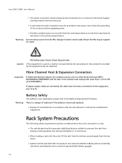
... NRTL) RECOGNISED COMPONENT and the laser in the module must be considered when the unit is user replaceable, please refer to the Battery Replacement Procedure. Warning Battery Safety The battery is mounted in a rack. • The rack design should always be disconnected prior to removal of the Power Supply/ Cooling module from the PSU. Acer S205F / S200F User's Manual • The power connection should incorporate stabilizing features suitable to prevent the...
... NRTL) RECOGNISED COMPONENT and the laser in the module must be considered when the unit is user replaceable, please refer to the Battery Replacement Procedure. Warning Battery Safety The battery is mounted in a rack. • The rack design should always be disconnected prior to removal of the Power Supply/ Cooling module from the PSU. Acer S205F / S200F User's Manual • The power connection should incorporate stabilizing features suitable to prevent the...

User Manual
Page 9
... may lose data. - The rack will require labelling with backplane components and module connectors, etc. Data Security • Power down your host computer and all conventional ESD precautions when handling Altos S205F / S200F Storage System plug-in each unit and the rack. • Each power supply in modules and components. Such use may also invalidate the warranty. • If you remove any drive module, you fit and check a suitable anti...
... may lose data. - The rack will require labelling with backplane components and module connectors, etc. Data Security • Power down your host computer and all conventional ESD precautions when handling Altos S205F / S200F Storage System plug-in each unit and the rack. • Each power supply in modules and components. Such use may also invalidate the warranty. • If you remove any drive module, you fit and check a suitable anti...

User Manual
Page 10
Related Documentation • Altos S200F Storage System Quick Installation Guide • Altos S205F Storage System Quick Installation Guide • Altos RAIDWatch User's Guide • Altos S205F Text-Mode Management Reference Guide x Special Tools and Equipment There are no special tools required but in order to complete the assembly of some configurations you may need the following (not supplied): • Security keys (one of these should be included with your backup routines. No...
Related Documentation • Altos S200F Storage System Quick Installation Guide • Altos S205F Storage System Quick Installation Guide • Altos RAIDWatch User's Guide • Altos S205F Text-Mode Management Reference Guide x Special Tools and Equipment There are no special tools required but in order to complete the assembly of some configurations you may need the following (not supplied): • Security keys (one of these should be included with your backup routines. No...

User Manual
Page 14
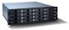
... appropriate switching card. • Dummy drive carrier modules. • Two plug-in Power Supply/Cooling modules: - The Backplane PCB provides logic level signal and low voltage power distribution paths. The chassis is fitted with 19 inch Rack mounting features which accommodates a plug-in drive carrier module. e.g. For Altos S205F - Figure 1-4 and Figure 1-5 show front and rear views of an Altos S200F Storage System chassis. This chassis assembly also includes an integral Operators (Ops) Panel, mounted at...
... appropriate switching card. • Dummy drive carrier modules. • Two plug-in Power Supply/Cooling modules: - The Backplane PCB provides logic level signal and low voltage power distribution paths. The chassis is fitted with 19 inch Rack mounting features which accommodates a plug-in drive carrier module. e.g. For Altos S205F - Figure 1-4 and Figure 1-5 show front and rear views of an Altos S200F Storage System chassis. This chassis assembly also includes an integral Operators (Ops) Panel, mounted at...
User Manual
Page 20
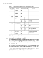
... cable interfacing with up to monitor internal functions. Processors housed on the Backplane, PSU, Controller and Ops Panel, to 16 SATA disk drives. The controller supports RAID levels 0, 1, 0+1, 3, 5, 10, 30 and 50. The module incorporates the following LED indicators: 8 While Altos S205F Storage System storage subsystem includes an enclosure with rear facing bays which houses one or two SATA control interface adaptor, known as RAID modules (see Figure 1-10). Altos S205F / S200F User's Manual Table 1-2 Altos S200F Ops Panel Switch Functions (Default settings at 2Gb/s) Switch...
... cable interfacing with up to monitor internal functions. Processors housed on the Backplane, PSU, Controller and Ops Panel, to 16 SATA disk drives. The controller supports RAID levels 0, 1, 0+1, 3, 5, 10, 30 and 50. The module incorporates the following LED indicators: 8 While Altos S205F Storage System storage subsystem includes an enclosure with rear facing bays which houses one or two SATA control interface adaptor, known as RAID modules (see Figure 1-10). Altos S205F / S200F User's Manual Table 1-2 Altos S200F Ops Panel Switch Functions (Default settings at 2Gb/s) Switch...
User Manual
Page 21
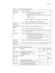
... GOOD. Introduction Table 1-3 Altos S205F RAID I/O Module LEDs LED Functions Color Description Battery Fail Amber When ON this LED denotes the following status: • When system is with power, ON denotes cache memory contains data or ECC errors are detected. • When system is without power, ON denotes cache memory contains data and is held up by BBU. Green Green Router Status Module Fault Storage Router Device Ready Green Storage Router Device not ready or...
... GOOD. Introduction Table 1-3 Altos S205F RAID I/O Module LEDs LED Functions Color Description Battery Fail Amber When ON this LED denotes the following status: • When system is with power, ON denotes cache memory contains data or ECC errors are detected. • When system is without power, ON denotes cache memory contains data and is held up by BBU. Green Green Router Status Module Fault Storage Router Device Ready Green Storage Router Device not ready or...

User Manual
Page 24
... are provided to the rear of the carrier handle. 12 There is attached to disable the normal 'pinch' latch action of each drive, thus improving system availability. 1.3.5.2 Drive Status Indicators Each drive carrier incorporates two indicators, an upper (Green) and lower (Amber). Altos S205F / S200F User's Manual Figure 1-12 Drive Carrier Module 1.3.5.1 SATA Transition Card For Serial ATA use a Transition card is one Transition card providing 1.5 Gb/s for standard...
... are provided to the rear of the carrier handle. 12 There is attached to disable the normal 'pinch' latch action of each drive, thus improving system availability. 1.3.5.2 Drive Status Indicators Each drive carrier incorporates two indicators, an upper (Green) and lower (Amber). Altos S205F / S200F User's Manual Figure 1-12 Drive Carrier Module 1.3.5.1 SATA Transition Card For Serial ATA use a Transition card is one Transition card providing 1.5 Gb/s for standard...

User Manual
Page 30
... reports on such topics as: - Altos S205F / S200F User's Manual 1.5.9 Important Drive Carrier Module Specification Please contact your supplier for details of approved drives. Module Dimensions Weight Transition card Operating Temperature Power Dissipation Height 29.1mm Width 106.55mm Depth 251 mm 0.98kg (1.0" 36Gb drive) Provides dual path emulation to Serial ATA drives. 5° C to 40° C (with non-approved drives may invalidate the warranty. Drive condition - Operator panel status 18 Enclosure temperature - Fan speed -
... reports on such topics as: - Altos S205F / S200F User's Manual 1.5.9 Important Drive Carrier Module Specification Please contact your supplier for details of approved drives. Module Dimensions Weight Transition card Operating Temperature Power Dissipation Height 29.1mm Width 106.55mm Depth 251 mm 0.98kg (1.0" 36Gb drive) Provides dual path emulation to Serial ATA drives. 5° C to 40° C (with non-approved drives may invalidate the warranty. Drive condition - Operator panel status 18 Enclosure temperature - Fan speed -

User Manual
Page 32
... be left completely empty. Acer S205F / S200F User's Manual Table 2-1 Altos S205F Storage System Configuration Module Location Blank I/O Module If only one module is fitted. Ops Panel (integral part of chassis assembly) Installed in the unused bay. Install the Power Supply/Cooling modules in rear bays 3 and 4. If only one RAID I/O moudle is installed a blank module must be fitted. Ops Panel (integral part of chassis assembly) Installed in rear Bay 2 Table 2-2 Altos S200F Storage System Configuration Module Location Drive Bays ALL drive bays must be fitted...
... be left completely empty. Acer S205F / S200F User's Manual Table 2-1 Altos S205F Storage System Configuration Module Location Blank I/O Module If only one module is fitted. Ops Panel (integral part of chassis assembly) Installed in the unused bay. Install the Power Supply/Cooling modules in rear bays 3 and 4. If only one RAID I/O moudle is installed a blank module must be fitted. Ops Panel (integral part of chassis assembly) Installed in rear Bay 2 Table 2-2 Altos S200F Storage System Configuration Module Location Drive Bays ALL drive bays must be fitted...

User Manual
Page 34
... rack space. Drive carrier module must always be installed without loss of drawer; These rails have fitted and checked a suitable anti-static wrist or ankle strap and observe all its carrier module. Avoid contact with all conventional ESD precautions when handling Altos S205F / S200F Storage System modules and components. This is the minimum configuration required for the system to operate and provide SES Management Services. 2.3 Enclosure Installation...
... rack space. Drive carrier module must always be installed without loss of drawer; These rails have fitted and checked a suitable anti-static wrist or ankle strap and observe all its carrier module. Avoid contact with all conventional ESD precautions when handling Altos S205F / S200F Storage System modules and components. This is the minimum configuration required for the system to operate and provide SES Management Services. 2.3 Enclosure Installation...

User Manual
Page 38
... host side interface and the SATA drives.The drives will not be hot plugged during operation. 26 The I /O module provides dual FC-AL SFP interface connections. Note When Logical Arrays are configured and mapped by the controller. Acer S205F / S200F User's Manual Figure 2-7 Installing an AC Power Supply Cooling Module (2) 2.5 RAID and JBOD I/O Module Configurations Important Please refer to section 2.10 for information on SATA drive configurations. 2.5.1 Internal Loop Structures The Altos S205F / S200F Storage System enclosure is configured with Fibre...
... host side interface and the SATA drives.The drives will not be hot plugged during operation. 26 The I /O module provides dual FC-AL SFP interface connections. Note When Logical Arrays are configured and mapped by the controller. Acer S205F / S200F User's Manual Figure 2-7 Installing an AC Power Supply Cooling Module (2) 2.5 RAID and JBOD I/O Module Configurations Important Please refer to section 2.10 for information on SATA drive configurations. 2.5.1 Internal Loop Structures The Altos S205F / S200F Storage System enclosure is configured with Fibre...
User Manual
Page 51
If the drives have been recently installed ensure they have had time to AMBER. 39 All LEDs on the Ops Panel should be lit Green at power up the enclosure please ensure that the system is activated (and the disk drive motors should be illuminated constant GREEN • If a problem is detected the color of the relevant LED will re-start ). Turn the Power Supply modules to...
If the drives have been recently installed ensure they have had time to AMBER. 39 All LEDs on the Ops Panel should be lit Green at power up the enclosure please ensure that the system is activated (and the disk drive motors should be illuminated constant GREEN • If a problem is detected the color of the relevant LED will re-start ). Turn the Power Supply modules to...

User Manual
Page 53
...; Remove AC at the power source 41 Off = 1Gb - It will be active). • if there is a drive fault 3.5 Power Down To power the Enclosure down, either • Switch off the Power Supply/Cooling modules installed in the enclosure should automatically start their motors. Operation Table 3-2 Ops Panel LED States LED Definition Color Normal Status Fault Status PSU Fault PSU Fault/ Cooling Temperature Fault Amber Off On 2Gb Link Speed Indicates link speed Green On = 2Gb - Hub Mode for Altos...
...; Remove AC at the power source 41 Off = 1Gb - It will be active). • if there is a drive fault 3.5 Power Down To power the Enclosure down, either • Switch off the Power Supply/Cooling modules installed in the enclosure should automatically start their motors. Operation Table 3-2 Ops Panel LED States LED Definition Color Normal Status Fault Status PSU Fault PSU Fault/ Cooling Temperature Fault Amber Off On 2Gb Link Speed Indicates link speed Green On = 2Gb - Hub Mode for Altos...

User Manual
Page 55
... The slot that controls access to protect important files (such as $,!, and /. Chassis A sheet metal enclosure incorporating a Backplane PCB and module runner system. I/O module (Serial ATA RAID or JBOD I /O modules and also the Ops Panel. ATA (Advance Technology Attachment) A disk drive interface standard based on a 16-bit bus and dealing with Start and Stop bits (for Information Interchange. The ATA "bus" only supports two devices - Often used to a specific file. The chassis contains a number of...
... The slot that controls access to protect important files (such as $,!, and /. Chassis A sheet metal enclosure incorporating a Backplane PCB and module runner system. I/O module (Serial ATA RAID or JBOD I /O modules and also the Ops Panel. ATA (Advance Technology Attachment) A disk drive interface standard based on a 16-bit bus and dealing with Start and Stop bits (for Information Interchange. The ATA "bus" only supports two devices - Often used to a specific file. The chassis contains a number of...

User Manual
Page 56
... interrupting the power supplies to exchange data. Serial Transmission The transfer of the Enclosure. An Altos S205F / S200F Storage System enclosure can have up the Altos S205F / S200F Storage System. The format of the operations that subsystem. Hot plugging A device with a replacement while the Altos S205F / S200F Storage System is used for use . SATA Serial ATA drive interface standard based on serial signaling technology, faster and using a single electrical path. 44 Altos S205F / S200F User's Manual Disk (drive, carrier, module) A SATA disk drive mounted in...
... interrupting the power supplies to exchange data. Serial Transmission The transfer of the Enclosure. An Altos S205F / S200F Storage System enclosure can have up the Altos S205F / S200F Storage System. The format of the operations that subsystem. Hot plugging A device with a replacement while the Altos S205F / S200F Storage System is used for use . SATA Serial ATA drive interface standard based on serial signaling technology, faster and using a single electrical path. 44 Altos S205F / S200F User's Manual Disk (drive, carrier, module) A SATA disk drive mounted in...
User Manual
Page 57
... System Interface/Operators Panel 6 ESD 22 expansion configuration 27 g grounding system checks 38 i IEC 320 connector 38 Index l LED 5, 6, 13 LED indicators 8 Li-ion battery pack 10 Logical Arrays 26 o Operators Panel 2, 6 Ops Panel 6, 13, 20, 23, 38, 39 Ops Panel LEDs 40 Ops Panel Switch Functions 7, 32 p plug-in module 2, 19 Power Down 41 Power On 39 power supply cord 24, 38 Power Supply/Cooling 2, 4, 5, 19, 20, 24, 38, 39 PSU LEDs 39 PSU voltage operating ranges 5 r Rack mounting 2 rack mounting rail kit...
... System Interface/Operators Panel 6 ESD 22 expansion configuration 27 g grounding system checks 38 i IEC 320 connector 38 Index l LED 5, 6, 13 LED indicators 8 Li-ion battery pack 10 Logical Arrays 26 o Operators Panel 2, 6 Ops Panel 6, 13, 20, 23, 38, 39 Ops Panel LEDs 40 Ops Panel Switch Functions 7, 32 p plug-in module 2, 19 Power Down 41 Power On 39 power supply cord 24, 38 Power Supply/Cooling 2, 4, 5, 19, 20, 24, 38, 39 PSU LEDs 39 PSU voltage operating ranges 5 r Rack mounting 2 rack mounting rail kit...


