Service Guide
Page 2
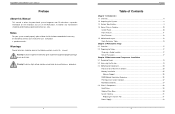
... and Component Installation 3.1 Removing Power ...19 3.2 Accessing the System ...19 3.3 Motherboard Components 20 Processor and Heatsink Installation 20 Memory Installation ...25 Memory Support ...25 DIMM Module Population Sequence 26 PCI Expansion Card Installation 27 Motherboard Battery ...27 3.4 Chassis Components...28 Hard Drives ...28 Optional Drive Bays...30 System Cooling ...31 Replacing the System Fan 31 Power Supply ...32 4 Warning! Notes For your system to work properly, please follow the links below to download all necessary drivers/utilities and the user's manual for...
... and Component Installation 3.1 Removing Power ...19 3.2 Accessing the System ...19 3.3 Motherboard Components 20 Processor and Heatsink Installation 20 Memory Installation ...25 Memory Support ...25 DIMM Module Population Sequence 26 PCI Expansion Card Installation 27 Motherboard Battery ...27 3.4 Chassis Components...28 Hard Drives ...28 Optional Drive Bays...30 System Cooling ...31 Replacing the System Fan 31 Power Supply ...32 4 Warning! Notes For your system to work properly, please follow the links below to download all necessary drivers/utilities and the user's manual for...
Service Guide
Page 3
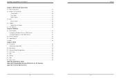
... Data Cables ...42 Power Cables...42 4.3 Ports ...43 Rear I/O Ports ...43 4.4 Jumpers ...45 Explanation of Jumpers 45 4.5 LED Indicators ...49 Chapter 5 Software 5.1 OS Installation ...51 Installing the Windows OS for a RAID System 51 Installing Windows to a Non-RAID System 51 5.2 Driver Installation ...52 5.3 SuperDoctor® 5...53 5.4 IPMI ...54 Chapter 6 BIOS 6.1 Introduction ...55 Starting the Setup Utility 55 6.2 Main Setup ...56 6.3 Advanced Setup Configurations 58 6.4 Event Logs...83 6.5 IPMI ...85 6.6 Security...88 6.7 Boot ...91 6.8 Save & Exit ...93 Appendix A BIOS Error Codes...
... Data Cables ...42 Power Cables...42 4.3 Ports ...43 Rear I/O Ports ...43 4.4 Jumpers ...45 Explanation of Jumpers 45 4.5 LED Indicators ...49 Chapter 5 Software 5.1 OS Installation ...51 Installing the Windows OS for a RAID System 51 Installing Windows to a Non-RAID System 51 5.2 Driver Installation ...52 5.3 SuperDoctor® 5...53 5.4 IPMI ...54 Chapter 6 BIOS 6.1 Introduction ...55 Starting the Setup Utility 55 6.2 Main Setup ...56 6.3 Advanced Setup Configurations 58 6.4 Event Logs...83 6.5 IPMI ...85 6.6 Security...88 6.7 Boot ...91 6.8 Save & Exit ...93 Appendix A BIOS Error Codes...
Service Guide
Page 5
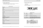
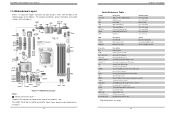
... Celeron processors Socket Type LGA 1151 (H4) Memory Four 288-pin DIMM slots to support up to the server. Use this function to identify the server from the power supply to 64 GB of the T110 F4. See Chapter 4 for more details on the control panel are described below Indicates activity on the hard drive when flashing Indicates network activity on the LAN port when flashing The main power button is on and red Blinking...
... Celeron processors Socket Type LGA 1151 (H4) Memory Four 288-pin DIMM slots to support up to the server. Use this function to identify the server from the power supply to 64 GB of the T110 F4. See Chapter 4 for more details on the control panel are described below Indicates activity on the hard drive when flashing Indicates network activity on the LAN port when flashing The main power button is on and red Blinking...
Service Guide
Page 7
... BMC I2C Header (for descriptions. Power On Connector BT1 COM1 Fan1-Fan4, FanA (IPMI) LAN I-SATA0-I-SATA5 I-SGPIO 1/2 JD1 JF1 JIPMB1 JL1 JPI2C1 JOH1 JPWR1 JPWR2 JSD1/JSD2 JSTBY1 JTPM1 JUIDB1 LAN1/LAN2 PCI-E (CPU) Slot 7 PCI-E (CPU) Slot 6 Description Onboard Battery COM1 (Serial Port) Header System/CPU Fan Headers Dedicated IPMI (RJ45) Port (Intel PCH) SATA (Serial ATA) 3.0 Ports Serial Link General Purpose I -SATA 7 ports shown above are used for test purposes only. SATA0 I User's Manual 1.5 Motherboard...
... BMC I2C Header (for descriptions. Power On Connector BT1 COM1 Fan1-Fan4, FanA (IPMI) LAN I-SATA0-I-SATA5 I-SGPIO 1/2 JD1 JF1 JIPMB1 JL1 JPI2C1 JOH1 JPWR1 JPWR2 JSD1/JSD2 JSTBY1 JTPM1 JUIDB1 LAN1/LAN2 PCI-E (CPU) Slot 7 PCI-E (CPU) Slot 6 Description Onboard Battery COM1 (Serial Port) Header System/CPU Fan Headers Dedicated IPMI (RJ45) Port (Intel PCH) SATA (Serial ATA) 3.0 Ports Serial Link General Purpose I -SATA 7 ports shown above are used for test purposes only. SATA0 I User's Manual 1.5 Motherboard...

Service Guide
Page 16
... 3.1. 1. Installing an Optional Device Begin by removing power from the system as a DVD-ROM. Slide the device into chassis. 6. If desired, screws may be used to secure the device into the chassis. 5. No tools or screws are required to the system. 4 Bracket Rail (A) 5 Figure 3-13. If the chassis fan fails, the system must be powered down before restoring power to install the system fan. If the power supply fan fails, the power supply itself must be replaced.
... 3.1. 1. Installing an Optional Device Begin by removing power from the system as a DVD-ROM. Slide the device into chassis. 6. If desired, screws may be used to secure the device into the chassis. 5. No tools or screws are required to the system. 4 Bracket Rail (A) 5 Figure 3-13. If the chassis fan fails, the system must be powered down before restoring power to install the system fan. If the power supply fan fails, the power supply itself must be replaced.

Service Guide
Page 24
...access the motherboard. 3. VGA Enable/Disable Jumper Settings Jumper Setting Definition Pins 1-2 Enabled Pins 2-3 Disabled 43 44 Remove the cover of these ports accept RJ45 cables. Connector Pins 3 21 Jumper Setting 3 21 Chapter 4: Motherboard Connections CMOS Clear JBT1 is located next to prevent accidentally clearing the contents of CMOS. Notes: Clearing CMOS will also clear any passwords. The default setting is located above the USB 0/1 ports. LAN Ports Two Gigabit Ethernet ports (LAN1 and LAN2) are used to clear CMOS. All of the chassis to enable or disable...
...access the motherboard. 3. VGA Enable/Disable Jumper Settings Jumper Setting Definition Pins 1-2 Enabled Pins 2-3 Disabled 43 44 Remove the cover of these ports accept RJ45 cables. Connector Pins 3 21 Jumper Setting 3 21 Chapter 4: Motherboard Connections CMOS Clear JBT1 is located next to prevent accidentally clearing the contents of CMOS. Notes: Clearing CMOS will also clear any passwords. The default setting is located above the USB 0/1 ports. LAN Ports Two Gigabit Ethernet ports (LAN1 and LAN2) are used to clear CMOS. All of the chassis to enable or disable...

Service Guide
Page 25
... Management Controller (BMC) to recover the BIOS settings on the motherboard. BIOS Recovery Jumper Settings Jumper Setting Definition Pins 1-2 Normal Pins 2-3 BIOS Recovery SMBus to PCI Slots Enable/Disable Use jumpers JI2C1 and JI2C2 to connect the System Management Bus (I2C) to the PCIExpress slots to disable it. SuperWorkstation 5039D-I User's Manual LAN1/2 Enable/Disable Change the setting of jumper JPME2 to bypass SPI flash security and force the system to operate in BIOS. The default setting is enabled, the user needs to write their own application software to improve PCI...
... Management Controller (BMC) to recover the BIOS settings on the motherboard. BIOS Recovery Jumper Settings Jumper Setting Definition Pins 1-2 Normal Pins 2-3 BIOS Recovery SMBus to PCI Slots Enable/Disable Use jumpers JI2C1 and JI2C2 to connect the System Management Bus (I2C) to the PCIExpress slots to disable it. SuperWorkstation 5039D-I User's Manual LAN1/2 Enable/Disable Change the setting of jumper JPME2 to bypass SPI flash security and force the system to operate in BIOS. The default setting is enabled, the user needs to write their own application software to improve PCI...
Service Guide
Page 27
... configure RAID settings (if using RAID) before moving on to the next item on your motherboard here, where you install the Windows OS and the software drivers. Choose the RAID driver indicated in the Windows OS Setup screen, then choose the hard drive in the DVD-ROM drive and the system will automatically reboot. SuperWorkstation 5039D-I User's Manual Chapter 5 Software After the hardware has been installed, you to view the entire contents. 5.3 IPMI 50 Insert Microsoft's Windows Setup DVD...
... configure RAID settings (if using RAID) before moving on to the next item on your motherboard here, where you install the Windows OS and the software drivers. Choose the RAID driver indicated in the Windows OS Setup screen, then choose the hard drive in the DVD-ROM drive and the system will automatically reboot. SuperWorkstation 5039D-I User's Manual Chapter 5 Software After the hardware has been installed, you to view the entire contents. 5.3 IPMI 50 Insert Microsoft's Windows Setup DVD...

Service Guide
Page 34
...-emphasis control on the SA (System Agent) side of a PCI-E port specified by the PCIE slot. The options are Enabled and Disabled. Press "+" or "-" on the power supplied by the user. The options are 1.0x, 0.1x, 0.01x, and 0.001x. 63 Chapter 6: BIOS CPU SLOT7 PCI-E 3.0 X8 SLOT7 Max Link Speed Use this item to configure the link speed of the DMI Link. The options are -6dB and -3.5dB. PEG Port Configuration CPU SLOT6 PCI...
...-emphasis control on the SA (System Agent) side of a PCI-E port specified by the PCIE slot. The options are Enabled and Disabled. Press "+" or "-" on the power supplied by the user. The options are 1.0x, 0.1x, 0.01x, and 0.001x. 63 Chapter 6: BIOS CPU SLOT7 PCI-E 3.0 X8 SLOT7 Max Link Speed Use this item to configure the link speed of the DMI Link. The options are -6dB and -3.5dB. PEG Port Configuration CPU SLOT6 PCI...

Service Guide
Page 35
... Enabled to disable ASPM support. Closed Loop Thermal Management Use this item to set the Active State Power Management (ASPM) level for a PCI-E device. Peer Memory Write Enable Use this feature to enable or disable the energy performance gain. SLOT4 L1 Substates Use this feature to set the ASPM level based on the system configuration. SLOT4 Detect Non-Compliance Device Select Enabled for the system BIOS to monitor the power consumption and temperature of the DMI Link...
... Enabled to disable ASPM support. Closed Loop Thermal Management Use this item to set the Active State Power Management (ASPM) level for a PCI-E device. Peer Memory Write Enable Use this feature to enable or disable the energy performance gain. SLOT4 L1 Substates Use this feature to set the ASPM level based on the system configuration. SLOT4 Detect Non-Compliance Device Select Enabled for the system BIOS to monitor the power consumption and temperature of the DMI Link...
Service Guide
Page 36
... which firmware type to be connected to a Solid State drive or a Hard Disk Drive. CPU SLOT6 PCI-E 3.0 X8 (IN X16) OPROM Use this feature to select which firmware type to be loaded for the add-on X11SSM-F only) Use this item to allow a PCI device to generate a PERR/SERR number for system boot. Disable this slot. SuperWorkstation 5039D-I User's Manual SLOT5 PCIe Speed Use this item to select the mode for the installed SATA drives. The options are Enabled and Disabled...
... which firmware type to be connected to a Solid State drive or a Hard Disk Drive. CPU SLOT6 PCI-E 3.0 X8 (IN X16) OPROM Use this feature to select which firmware type to be loaded for the add-on X11SSM-F only) Use this item to allow a PCI device to generate a PERR/SERR number for system boot. Disable this slot. SuperWorkstation 5039D-I User's Manual SLOT5 PCIe Speed Use this item to select the mode for the installed SATA drives. The options are Enabled and Disabled...
Service Guide
Page 37
... enable IPv6 PXE boot support. DMA), (IO=2F8h; DMA). Serial Port 2 Serial Port 2 Configuration This submenu allows the user the configure settings of device installed in LAN Port1 used as the primary boot device. IRQ=4; IRQ=3, 4, 5, 6, 7, 9, 10, 11, 12; The options are Enabled and Disabled. SuperWorkstation 5039D-I User's Manual CPU SLOT 7 PCI-E 3.0 X8 OPROM Use this feature to select which firmware type to be loaded for LAN2 Option ROM is Disabled. The options are Enabled and Disabled. Serial Port 2 Select Enabled to enable IPv4 PXE boot support. The default setting...
... enable IPv6 PXE boot support. DMA), (IO=2F8h; DMA). Serial Port 2 Serial Port 2 Configuration This submenu allows the user the configure settings of device installed in LAN Port1 used as the primary boot device. IRQ=4; IRQ=3, 4, 5, 6, 7, 9, 10, 11, 12; The options are Enabled and Disabled. SuperWorkstation 5039D-I User's Manual CPU SLOT 7 PCI-E 3.0 X8 OPROM Use this feature to select which firmware type to be loaded for LAN2 Option ROM is Disabled. The options are Enabled and Disabled. Serial Port 2 Select Enabled to enable IPv4 PXE boot support. The default setting...
Service Guide
Page 38
... Stop Bits A stop sending data when the receiving buffer is the remote computer used . COM1 Flow Control Use this feature to set to Enabled, the following Intel Server Platform Services information will exchange data with the client computer, which is full. Send a "Start" signal to 0, and the number of a serial data packet. IRQ=3, 4, 5, 6, 7, 9, 10, 11, 12; COM1 Terminal Type This feature allows the user to prevent data loss...
... Stop Bits A stop sending data when the receiving buffer is the remote computer used . COM1 Flow Control Use this feature to set to Enabled, the following Intel Server Platform Services information will exchange data with the client computer, which is full. Send a "Start" signal to 0, and the number of a serial data packet. IRQ=3, 4, 5, 6, 7, 9, 10, 11, 12; COM1 Terminal Type This feature allows the user to prevent data loss...
Service Guide
Page 39
... Enabled to capture the data displayed on a terminal and send it as text messages to a remote server. The options are VT100, LINUX, XTERMR6, SC0, ESCN, and VT400. Select ANSI to specify how the host computer will become available for user's configuration: SOL/COM2 Console Redirection Settings Use this feature to set the transmission speed for standard serial data communication. Select Space to add a Space as a parity bit...
... Enabled to capture the data displayed on a terminal and send it as text messages to a remote server. The options are VT100, LINUX, XTERMR6, SC0, ESCN, and VT400. Select ANSI to specify how the host computer will become available for user's configuration: SOL/COM2 Console Redirection Settings Use this feature to set the transmission speed for standard serial data communication. Select Space to add a Space as a parity bit...
Service Guide
Page 40
... VT100, LINUX, XTERMR6, SCO, ESCN, and VT400. Data Bits Use this feature to Bootloader, legacy Console Redirection is set to enable or disable legacy Console Redirection after BIOS POST. Select None if you do not want to set to communicate with regular data bits to select the target terminal emulation type for Console Redirection. The High Performance Event Timer is used by the user for user's configuration: EMS Console Redirection Settings This...
... VT100, LINUX, XTERMR6, SCO, ESCN, and VT400. Data Bits Use this feature to Bootloader, legacy Console Redirection is set to enable or disable legacy Console Redirection after BIOS POST. Select None if you do not want to set to communicate with regular data bits to select the target terminal emulation type for Console Redirection. The High Performance Event Timer is used by the user for user's configuration: EMS Console Redirection Settings This...

Service Guide
Page 41
... restrict support for both set to Enabled, onbaord security devices will restart to specify the port speed used for the selected boot protocol. The options are None and TPM Clear. Blink LEDs Use this feature to enable or disable TXT Support. The following items. Add an Attempt Delete Attempts Change Attempt order Intel I210 Gigabit Network Connection - OC:C4:7A:1A:44:CE NIC Configuration Link Speed This...
... restrict support for both set to Enabled, onbaord security devices will restart to specify the port speed used for the selected boot protocol. The options are None and TPM Clear. Blink LEDs Use this feature to enable or disable TXT Support. The following items. Add an Attempt Delete Attempts Change Attempt order Intel I210 Gigabit Network Connection - OC:C4:7A:1A:44:CE NIC Configuration Link Speed This...

Service Guide
Page 60
SATA Controller On-chip (C232) controller Drive Bays Up to four 3.5" or 2.5" internal drives PCI Expansion Slots One PCI Express 3.0 x4 in x8 slots (PCH slot 5) One PCI Express 3.0 x8 in LGA 1151 (H4) type socket Note: Please refer to the motherboard specifications pages on our website for updates to supported processors. See www.dtsc.ca.gov/ hazardouswaste/perchlorate" 115 SuperWorkstation 5039D-I User's Manual Appendix C System Specifications Processors Single Intel® E3-1200 v5...
SATA Controller On-chip (C232) controller Drive Bays Up to four 3.5" or 2.5" internal drives PCI Expansion Slots One PCI Express 3.0 x4 in x8 slots (PCH slot 5) One PCI Express 3.0 x8 in LGA 1151 (H4) type socket Note: Please refer to the motherboard specifications pages on our website for updates to supported processors. See www.dtsc.ca.gov/ hazardouswaste/perchlorate" 115 SuperWorkstation 5039D-I User's Manual Appendix C System Specifications Processors Single Intel® E3-1200 v5...

Installation Guide
Page 3
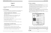
Altos T110 F3 Installation Configuration Guide CONTENTS INTRODUCTION 1 WINDOWS SERVER 2012 R2 2 Intel Onboard SATA RAID 2 BIOS Required 2 Drivers Required 2 Software Required 2 Configuring Intel Onboard SATA RAID 2 Installation Tips 2 Chipset Driver Package Installation 3 Gigabit Ethernet Driver Installation 3 VGA Driver Installation 4 USB 3.0 Driver Installation 4 RAID Utility Installation 4 RED HAT ENTERPRISE LINUX 7.3 5 Intel Onboard SATA (No RAID) 5 BIOS Required 5 Drivers Required 5 Installation Tips 5 Gigabit Ethernet Driver Installation 5 VGA ...
Altos T110 F3 Installation Configuration Guide CONTENTS INTRODUCTION 1 WINDOWS SERVER 2012 R2 2 Intel Onboard SATA RAID 2 BIOS Required 2 Drivers Required 2 Software Required 2 Configuring Intel Onboard SATA RAID 2 Installation Tips 2 Chipset Driver Package Installation 3 Gigabit Ethernet Driver Installation 3 VGA Driver Installation 4 USB 3.0 Driver Installation 4 RAID Utility Installation 4 RED HAT ENTERPRISE LINUX 7.3 5 Intel Onboard SATA (No RAID) 5 BIOS Required 5 Drivers Required 5 Installation Tips 5 Gigabit Ethernet Driver Installation 5 VGA ...
Installation Guide
Page 7
... Software RAID driver for Windows. 4. Follow the instructions, accept the license agreement and use the default setting to install USB 3.0 driver manually. Select Windows Server 2012 R2 then click on Autorun.exe. 7. The driver and PROSet utility will be installed together automatically. You don't need to install VGA driver manually. Select Resource Kit. 2. Find the RSTe Utility by expanding the directory in the following order, Altos T110 F4 -> (On Board)LAN -> Intel PRO Network Connections Drivers. 5. After the installation is completed, reboot...
... Software RAID driver for Windows. 4. Follow the instructions, accept the license agreement and use the default setting to install USB 3.0 driver manually. Select Windows Server 2012 R2 then click on Autorun.exe. 7. The driver and PROSet utility will be installed together automatically. You don't need to install VGA driver manually. Select Resource Kit. 2. Find the RSTe Utility by expanding the directory in the following order, Altos T110 F4 -> (On Board)LAN -> Intel PRO Network Connections Drivers. 5. After the installation is completed, reboot...
Installation Guide
Page 8
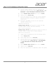
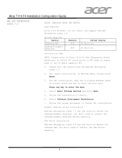
... following message shows on screen, press any key to enter the boot menu Press any key to install. 6. For legacy installation, at Welcome Menu, Please press Enter. 3. Follow the normal procedure to install the VGA driver manually. 5 You don't need to select OS installation in Installation Tips NOTE. Select Basic Storage Devices and press Next. 5. Altos T110 F4 Installation Configuration Guide RED HAT ENTERPRISE LINUX 7.3 Intel Onboard SATA (No RAID) BIOS Required Altos T110 F4 BIOS 1.0b (or later) can support...
... following message shows on screen, press any key to enter the boot menu Press any key to install. 6. For legacy installation, at Welcome Menu, Please press Enter. 3. Follow the normal procedure to install the VGA driver manually. 5 You don't need to select OS installation in Installation Tips NOTE. Select Basic Storage Devices and press Next. 5. Altos T110 F4 Installation Configuration Guide RED HAT ENTERPRISE LINUX 7.3 Intel Onboard SATA (No RAID) BIOS Required Altos T110 F4 BIOS 1.0b (or later) can support...


