
Service Guide
Page 2
... for the installation and use of Contents Chapter 1 Introduction 1.1 Overview...8 1.2 Unpacking the System...8 1.3 System Specifications...9 1.4 Server Chassis Features 10 Control Panel...10 Front Features ...11 Rear Features ...12 1.5 Motherboard Layout...13 Quick Reference Table ...14 Chapter... 2 Workstation Setup 2.1 Overview...17 2.2 Preparing for Setup ...17 Choosing a Setup Location 17 Server Precautions ...17 Chapter 3 Maintenance and Component Installation 3.1 Removing Power ...19 3.2 Accessing the System ...19 3.3 Motherboard Components 20...
... for the installation and use of Contents Chapter 1 Introduction 1.1 Overview...8 1.2 Unpacking the System...8 1.3 System Specifications...9 1.4 Server Chassis Features 10 Control Panel...10 Front Features ...11 Rear Features ...12 1.5 Motherboard Layout...13 Quick Reference Table ...14 Chapter... 2 Workstation Setup 2.1 Overview...17 2.2 Preparing for Setup ...17 Choosing a Setup Location 17 Server Precautions ...17 Chapter 3 Maintenance and Component Installation 3.1 Removing Power ...19 3.2 Accessing the System ...19 3.3 Motherboard Components 20...
Service Guide
Page 5
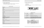
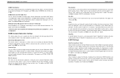
... overheat condition has occured. (This may be caused by cable congestion.) Fan failure, check for an inoperative fan. Please refer to 64 GB of the T110 F4. Turning off system power with PFC Form Factor Mini tower Dimensions (WxHxD) 7.25 x 14.25 x 16.75 in a rackmount environment. Local UID ...(PCH slot 5) One PCI Express 3.0 x8 in x16 slot (CPU slot 6) One PCI Express 3.0 x8 slot (CPU slot 7) Hard Drives Up to locate the server in . (184 x 362 x 425 mm) 8 Chapter 1: Introduction 1.4 System Chassis Features Control Panel The switches and LEDs located on the control panel are described ...
... overheat condition has occured. (This may be caused by cable congestion.) Fan failure, check for an inoperative fan. Please refer to 64 GB of the T110 F4. Turning off system power with PFC Form Factor Mini tower Dimensions (WxHxD) 7.25 x 14.25 x 16.75 in a rackmount environment. Local UID ...(PCH slot 5) One PCI Express 3.0 x8 in x16 slot (CPU slot 6) One PCI Express 3.0 x8 slot (CPU slot 7) Hard Drives Up to locate the server in . (184 x 362 x 425 mm) 8 Chapter 1: Introduction 1.4 System Chassis Features Control Panel The switches and LEDs located on the control panel are described ...

Service Guide
Page 25
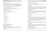
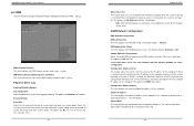
... Dog is Reset. These two jumpers should be enabled in the manufacturer mode, which will allow the user to flash the system firmware from a host server for system setting modifications. Watch Dog Jumper Settings Jumper Setting Definition Pins 1-2 Reset Pins 2-3 NMI Open Disabled Manufacturer Mode Select Close pins 2 and 3 of jumper...
... Dog is Reset. These two jumpers should be enabled in the manufacturer mode, which will allow the user to flash the system firmware from a host server for system setting modifications. Watch Dog Jumper Settings Jumper Setting Definition Pins 1-2 Reset Pins 2-3 NMI Open Disabled Manufacturer Mode Select Close pins 2 and 3 of jumper...
Service Guide
Page 38
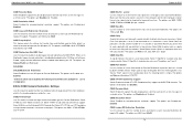
...=2F8h; IRQ=3, 4, 5, 6, 7, 9, 10, 11, 12; Select VT-UTF8 to use COM Port 2 as a parity bit to Enabled, the following Intel Server Platform Services information will exchange data with your data bits. A lower transmission speed may be sent along with your data bits in Console Redirection. Select...and busy lines. Select Auto to allow the BIOS to detect data transmission errors. The options are SOL and COM. Intel Server Platform Services The following items will become available for Console Redirection to specify how the host computer will display: • ME BIOS...
...=2F8h; IRQ=3, 4, 5, 6, 7, 9, 10, 11, 12; Select VT-UTF8 to use COM Port 2 as a parity bit to Enabled, the following Intel Server Platform Services information will exchange data with your data bits. A lower transmission speed may be sent along with your data bits in Console Redirection. Select...and busy lines. Select Auto to allow the BIOS to detect data transmission errors. The options are SOL and COM. Intel Server Platform Services The following items will become available for Console Redirection to specify how the host computer will display: • ME BIOS...
Service Guide
Page 39
... Console Redirection. COM2 Recorder Mode Select Enabled to capture the data displayed on a terminal and send it as text messages to a remote server. COM1 Putty KeyPad This feature selects the settings for Function Keys and KeyPad used for Console Redirection. COM2 Terminal Type Use this feature to...5039D-I User's Manual COM1 Recorder Mode Select Enabled to capture the data displayed on a terminal and send it as text messages to a remote server. The options are 9600, 19200, 38400, 57600 and 115200 (bits per second). SOL/COM2 SOL/COM2 Console Redirection Select Enabled to use UTF8 ...
... Console Redirection. COM2 Recorder Mode Select Enabled to capture the data displayed on a terminal and send it as text messages to a remote server. COM1 Putty KeyPad This feature selects the settings for Function Keys and KeyPad used for Console Redirection. COM2 Terminal Type Use this feature to...5039D-I User's Manual COM1 Recorder Mode Select Enabled to capture the data displayed on a terminal and send it as text messages to a remote server. The options are 9600, 19200, 38400, 57600 and 115200 (bits per second). SOL/COM2 SOL/COM2 Console Redirection Select Enabled to use UTF8 ...
Service Guide
Page 40
When set to Enabled, the following items will exchange data with a remote host server. The options are Enabled and Disabled. *If the item above set to add color and function key support. The options are None, Hardware RTS/CTS, ... VT400. Select VT100 to 0, and the number of a serial data packet. The options are used to send a parity bit with your data bits in a client server to detect data transmission errors. Select 2 Stop Bits if slower devices are None, Even, Odd, Mark and Space. SuperWorkstation 5039D-I User's Manual COM2 Putty KeyPad...
When set to Enabled, the following items will exchange data with a remote host server. The options are Enabled and Disabled. *If the item above set to add color and function key support. The options are None, Hardware RTS/CTS, ... VT400. Select VT100 to 0, and the number of a serial data packet. The options are used to send a parity bit with your data bits in a client server to detect data transmission errors. Select 2 Stop Bits if slower devices are None, Even, Odd, Mark and Space. SuperWorkstation 5039D-I User's Manual COM2 Putty KeyPad...
Service Guide
Page 44
... Event Log Enabling/Disabling Options SEL Components Select Enabled for the BIOS to Yes, the following item will search for a DHCP (Dynamic Host Configuration Protocol) server in dotted quad form (i.e., 192.168.10.253). The options are No and Yes. *If the item above set to implement all system event logs...
... Event Log Enabling/Disabling Options SEL Components Select Enabled for the BIOS to Yes, the following item will search for a DHCP (Dynamic Host Configuration Protocol) server in dotted quad form (i.e., 192.168.10.253). The options are No and Yes. *If the item above set to implement all system event logs...

Installation Guide
Page 3
Altos T110 F3 Installation Configuration Guide CONTENTS INTRODUCTION 1 WINDOWS SERVER 2012 R2 2 Intel Onboard SATA RAID 2 BIOS Required 2 Drivers Required 2 Software Required 2 Configuring Intel Onboard SATA RAID 2 Installation Tips 2 Chipset Driver Package Installation 3 Gigabit Ethernet ...
Altos T110 F3 Installation Configuration Guide CONTENTS INTRODUCTION 1 WINDOWS SERVER 2012 R2 2 Intel Onboard SATA RAID 2 BIOS Required 2 Drivers Required 2 Software Required 2 Configuring Intel Onboard SATA RAID 2 Installation Tips 2 Chipset Driver Package Installation 3 Gigabit Ethernet ...

Installation Guide
Page 4
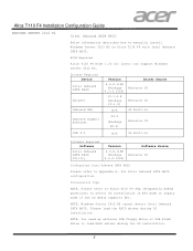
Altos T110 F4 Installation Configuration Guide INTRODUCTION The driver required for installing the OS manually is included in Resource CD, this document provides you a OS installation guide on Altos T110 F4, including, Windows Server 2012 R2 Red Hat Enterprise Linux 7.3 1
Altos T110 F4 Installation Configuration Guide INTRODUCTION The driver required for installing the OS manually is included in Resource CD, this document provides you a OS installation guide on Altos T110 F4, including, Windows Server 2012 R2 Red Hat Enterprise Linux 7.3 1
Installation Guide
Page 5
... You need an external USB floppy drive or USB Flash drive to manually install Windows Server 2012 R2 on Altos T110 F4 with Intel Onboard SATA RAID. Please refer to Altos T110 F4 FAQ (Frequently Asked Questions) to select OS installation in Software Required Software Intel Onboard SATA... (Package Resource CD 4.3.0.1223) Configuring Intel Onboard SATA RAID Please refer to Appendix A. NOTE. BIOS Required Altos T110 F4 BIOS 1.0b (or later) can support Windows Server 2012 R2. Drivers Required Device Intel Onboard SATA RAID Chipset Onboard VGA Onboard Gigabit Ethernet Version Driver Source ...
... You need an external USB floppy drive or USB Flash drive to manually install Windows Server 2012 R2 on Altos T110 F4 with Intel Onboard SATA RAID. Please refer to Altos T110 F4 FAQ (Frequently Asked Questions) to select OS installation in Software Required Software Intel Onboard SATA... (Package Resource CD 4.3.0.1223) Configuring Intel Onboard SATA RAID Please refer to Appendix A. NOTE. BIOS Required Altos T110 F4 BIOS 1.0b (or later) can support Windows Server 2012 R2. Drivers Required Device Intel Onboard SATA RAID Chipset Onboard VGA Onboard Gigabit Ethernet Version Driver Source ...
Installation Guide
Page 6
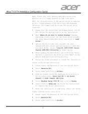
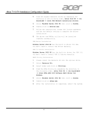
...into the optical drive. 2. Select model and click on "Load Driver". 3. Find the Chipset Driver by expanding the directory in the following order, Altos T110 F4 -> (On board) Chipset -> Intel Chipset INF files. 5. After the installation is required as target driver. 4. Select Resource Kit. 3. Please ... the USB flash which includes the Intel Onboard SATA RAID driver and click on Drivers. 4. Gigabit Ethernet Driver Installation 1. Select Windows Server 2012 R2 then click on Drivers. 3 Please boot the system from Resource CD to complete the driver installation. 7. Please insert the...
...into the optical drive. 2. Select model and click on "Load Driver". 3. Find the Chipset Driver by expanding the directory in the following order, Altos T110 F4 -> (On board) Chipset -> Intel Chipset INF files. 5. After the installation is required as target driver. 4. Select Resource Kit. 3. Please ... the USB flash which includes the Intel Onboard SATA RAID driver and click on Drivers. 4. Gigabit Ethernet Driver Installation 1. Select Windows Server 2012 R2 then click on Drivers. 3 Please boot the system from Resource CD to complete the driver installation. 7. Please insert the...
Installation Guide
Page 7
...manually. Select Resource Kit. 2. Double-click on Autorun.exe. 7. Select Windows Server 2012 R2 then click on Browse. 5. Find the Gigabit Ethernet Driver by expanding the directory in the following order, Altos T110 F4 -> (On board)RAID -> Intel RSTe AHCI SCU Software RAID driver for ...Windows. 4. You don't need to complete the driver installation. 8. USB 3.0 Driver Installation Windows Server 2012 R2 has the built-in driver for USB...
...manually. Select Resource Kit. 2. Double-click on Autorun.exe. 7. Select Windows Server 2012 R2 then click on Browse. 5. Find the Gigabit Ethernet Driver by expanding the directory in the following order, Altos T110 F4 -> (On board)RAID -> Intel RSTe AHCI SCU Software RAID driver for ...Windows. 4. You don't need to complete the driver installation. 8. USB 3.0 Driver Installation Windows Server 2012 R2 has the built-in driver for USB...


