Aspire 3610 Service Guide
Page 49
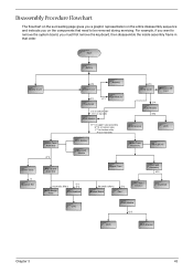
For example, if you want to be removed during servicing. Start Battery Middle Cover H*2 DIMM Cover Memory P*1 Keyboard ODD Module E*1 J*2 on bottom side K*2 on top side LCD Module E*1 on upper case assemby E*12 on bottom side F*3 on bottom side A*2 on rear side H*3 HDD Cover Wireless LAN Card O*4 HDD Module M*4 HDD Bracket HDD Lower Case Assembly...
For example, if you want to be removed during servicing. Start Battery Middle Cover H*2 DIMM Cover Memory P*1 Keyboard ODD Module E*1 J*2 on bottom side K*2 on top side LCD Module E*1 on upper case assemby E*12 on bottom side F*3 on bottom side A*2 on rear side H*3 HDD Cover Wireless LAN Card O*4 HDD Module M*4 HDD Bracket HDD Lower Case Assembly...
Aspire 3610 Service Guide
Page 52
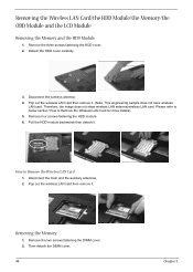
... the wireless antenna. 4. Remove four screws fastening the HDD module. 6. Remove the three screws fastening the HDD cover. 2. Please refer to below section "How to Remove the Wireless LAN Card 1. Pop out the wireless LAN card then remove it . (Note: This engineering sample ... the auxiliary antennae. 2. Pull the HDD module backwards then detach it. How to Remove the Wireless LAN Card for more details). 5. Then detach the DIMM cover. 46 Chapter 3 Removing the Memory 1. Removing the Wireless LAN Card/the HDD Module/the Memory/the ODD Module and the...
... the wireless antenna. 4. Remove four screws fastening the HDD module. 6. Remove the three screws fastening the HDD cover. 2. Please refer to below section "How to Remove the Wireless LAN Card 1. Pop out the wireless LAN card then remove it . (Note: This engineering sample ... the auxiliary antennae. 2. Pull the HDD module backwards then detach it. How to Remove the Wireless LAN Card for more details). 5. Then detach the DIMM cover. 46 Chapter 3 Removing the Memory 1. Removing the Wireless LAN Card/the HDD Module/the Memory/the ODD Module and the...
Aspire 3610 Service Guide
Page 53
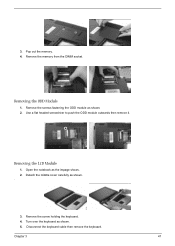
Removing the LCD Module 1. Detach the middle cover carefully as the impage shows. 2. Pop out the memory. 4. Remove the memory from the DIMM socket. Open the notebook as shown. . 3. 3. Removing the ODD Module 1. Remove the screws fastening the ODD module as shown. 5. Turn over the keyboard as shown. 2. Chapter 3 47 Remove the screw holding the keyboard. 4. Disconnect the keyboard cable then remove the keyboard. Use a flat headed screwdriver to push the ODD module outwards then remove it.
Removing the LCD Module 1. Detach the middle cover carefully as the impage shows. 2. Pop out the memory. 4. Remove the memory from the DIMM socket. Open the notebook as shown. . 3. 3. Removing the ODD Module 1. Remove the screws fastening the ODD module as shown. 5. Turn over the keyboard as shown. 2. Chapter 3 47 Remove the screw holding the keyboard. 4. Disconnect the keyboard cable then remove the keyboard. Use a flat headed screwdriver to push the ODD module outwards then remove it.
Aspire 3610 Service Guide
Page 59
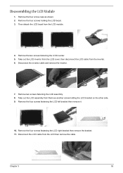
... screw caps as shown. 2. Take out the LCD inverter from the LCD cover, then disconnect the LCD cable from the LCD module. 4. Remove two screws fastening the LCD assembly. 8. Remove the two screws fastening the LCD inverter. 5. Disconnect the inverter cable and remove the inverter. 7. Take out the LCD assembly from the LCD then remove the cable. Disconnect the...
... screw caps as shown. 2. Take out the LCD inverter from the LCD cover, then disconnect the LCD cable from the LCD module. 4. Remove two screws fastening the LCD assembly. 8. Remove the two screws fastening the LCD inverter. 5. Disconnect the inverter cable and remove the inverter. 7. Take out the LCD assembly from the LCD then remove the cable. Disconnect the...

Aspire 3610 Service Guide
Page 75
...) appears different from hibernation mode. The system doesn't resume from standby mode after closing the LCD The system doesn't resume from actual size. LCD cover switch System board See "Save to execute "Load Default Settings, then reboot system. LCD cover switch System board Chapter 4 69 Keyboard (if control is damaged. Power-Related Symptoms Symptom / Error... beeps every minute. Action in Sequence Enter BIOS Setup Utility to Disk (S4)" on page 26. The system doesn't enter standby mode after opening the LCD.
...) appears different from hibernation mode. The system doesn't resume from standby mode after closing the LCD The system doesn't resume from actual size. LCD cover switch System board See "Save to execute "Load Default Settings, then reboot system. LCD cover switch System board Chapter 4 69 Keyboard (if control is damaged. Power-Related Symptoms Symptom / Error... beeps every minute. Action in Sequence Enter BIOS Setup Utility to Disk (S4)" on page 26. The system doesn't enter standby mode after opening the LCD.


