Aspire 7720 / 7720G Service Guide
Page 11
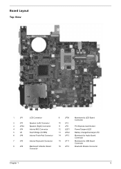
... 3 JP34 Speaker (Right) Connector 11 JP9 PCI Express Card Socket 4 JP4 Internal MIC Connector 12 LED1 Power/Suspend LED 5 U5 South Bridge (ICH8M) 13 LED2 Battery Charge/Discharge LED 6 JP6 Internal Track-Pad Connector 14 JP13 Mainboard to Audio Board Connector 7 JP5 Internal Keyboard Connector 15 JP11 Mainboard to USB Board...
... 3 JP34 Speaker (Right) Connector 11 JP9 PCI Express Card Socket 4 JP4 Internal MIC Connector 12 LED1 Power/Suspend LED 5 U5 South Bridge (ICH8M) 13 LED2 Battery Charge/Discharge LED 6 JP6 Internal Track-Pad Connector 14 JP13 Mainboard to Audio Board Connector 7 JP5 Internal Keyboard Connector 15 JP11 Mainboard to USB Board...
Aspire 7720 / 7720G Service Guide
Page 14
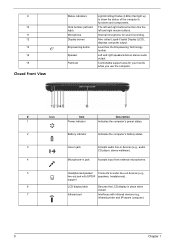
...-aware computer). 8 Chapter 1 Internal microphone for your hands when you use the computer. # Icon Item Description 1 Power indicator Indicates the computer's power status. 2 Battery indicator Indicates the computer's battery status. 3 Line-in jack Accepts audio line-in devices (e.g., audio CD player, stereo walkman). 4 Microphone-in place when closed. 7 Infrared port Interfaces with...
...-aware computer). 8 Chapter 1 Internal microphone for your hands when you use the computer. # Icon Item Description 1 Power indicator Indicates the computer's power status. 2 Battery indicator Indicates the computer's battery status. 3 Line-in jack Accepts audio line-in devices (e.g., audio CD player, stereo walkman). 4 Microphone-in place when closed. 7 Infrared port Interfaces with...
Aspire 7720 / 7720G Service Guide
Page 17
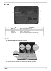
Chapter 1 11 Note: Do not cover or obstruct the opening of the fan. Base view # 1 2 3 4 5 & 6 Item Battery bay Battery release latch Battery lock Hard disk bay Ventilation slots and cooling fan Description Houses the computer's battery pack. Houses the computer's hard disk (secured with screws) Enable the computer to -read status indicators. Releases the battery for removal. Locks the battery in position. Indicators The computer has several easy-to stay cool, even after prolonged use. The front panel indicators are visible even when the computer cover is closed up.
Chapter 1 11 Note: Do not cover or obstruct the opening of the fan. Base view # 1 2 3 4 5 & 6 Item Battery bay Battery release latch Battery lock Hard disk bay Ventilation slots and cooling fan Description Houses the computer's battery pack. Houses the computer's hard disk (secured with screws) Enable the computer to -read status indicators. Releases the battery for removal. Locks the battery in position. Indicators The computer has several easy-to stay cool, even after prolonged use. The front panel indicators are visible even when the computer cover is closed up.

Aspire 7720 / 7720G Service Guide
Page 18
... Manager. 12 Chapter 1 Charging: The light shows amber when the battery is active. Press " " to email and Internet programs, but can be reset by users. Icon Function Power Battery Description Lights up when the battery is being charged. Easy-Launch Buttons To the top of the keyboard... there are pre-set the Web browser and mail buttons, run the Acer Empowering Technology. The mail and Web browser buttons ...
... Manager. 12 Chapter 1 Charging: The light shows amber when the battery is active. Press " " to email and Internet programs, but can be reset by users. Icon Function Power Battery Description Lights up when the battery is being charged. Easy-Launch Buttons To the top of the keyboard... there are pre-set the Web browser and mail buttons, run the Acer Empowering Technology. The mail and Web browser buttons ...

Aspire 7720 / 7720G Service Guide
Page 24
... start the program from the Start menu. If you do so when running Acer eLock Management or Acer eRecovery Management for you to location-based networks intelligently. T Acer eSettings Management accesses system information and adjusts settings easily. T Acer ePower Management extends battery power via versatile usage profiles. To access this utility, either click on the...
... start the program from the Start menu. If you do so when running Acer eLock Management or Acer eRecovery Management for you to location-based networks intelligently. T Acer eSettings Management accesses system information and adjusts settings easily. T Acer ePower Management extends battery power via versatile usage profiles. To access this utility, either click on the...

Aspire 7720 / 7720G Service Guide
Page 26
...the " " icon shown on /off: Wireless LAN, Bluetooth, CardBus, FireWire (1394), Wired LAN and Optical Device if supported. DC Mode (Battery mode) There are three pre-defined profiles - Change the display and sleep settings as desired. 5. You can adjust CPU speed, LCD brightness ...settings, or click on buttons to apply the setting. 6. To launch it, select Acer ePower Management from the Empowering Technology interface. Enter the name for your needs. Acer ePower Management Acer ePower Management features a straightforward user interface. Select one of the predefined power plan that...
...the " " icon shown on /off: Wireless LAN, Bluetooth, CardBus, FireWire (1394), Wired LAN and Optical Device if supported. DC Mode (Battery mode) There are three pre-defined profiles - Change the display and sleep settings as desired. 5. You can adjust CPU speed, LCD brightness ...settings, or click on buttons to apply the setting. 6. To launch it, select Acer ePower Management from the Empowering Technology interface. Enter the name for your needs. Acer ePower Management Acer ePower Management features a straightforward user interface. Select one of the predefined power plan that...
Aspire 7720 / 7720G Service Guide
Page 27
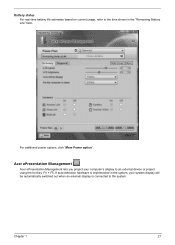
If auto-detection hardware is connected to the system. Chapter 1 21 For additional power options, click "More Power option". Battery status For real-time battery life estimates based on current usage, refer to an external device or project using the hot key: Fn + F5. Acer ePresentation Management Acer ePresentation Management lets you project your system display will be automatically switched out when an external display is implemented in the system, your computer's display to the time shown in the "Remaining Battery Life" field.
If auto-detection hardware is connected to the system. Chapter 1 21 For additional power options, click "More Power option". Battery status For real-time battery life estimates based on current usage, refer to an external device or project using the hot key: Fn + F5. Acer ePresentation Management Acer ePresentation Management lets you project your system display will be automatically switched out when an external display is implemented in the system, your computer's display to the time shown in the "Remaining Battery Life" field.

Aspire 7720 / 7720G Service Guide
Page 57
... bootable diskette. Chapter 2 51 Copy the flash utilities to update the system BIOS flash ROM. Use the Phlash utility to the bootable diskette. 3. If the battery pack does not contain enough power to run the Phlash utility. Follow the steps below to finish BIOS flash, you use the Phlash. NOTE: Do...
... bootable diskette. Chapter 2 51 Copy the flash utilities to update the system BIOS flash ROM. Use the Phlash utility to the bootable diskette. 3. If the battery pack does not contain enough power to run the Phlash utility. Follow the steps below to finish BIOS flash, you use the Phlash. NOTE: Do...
Aspire 7720 / 7720G Service Guide
Page 60
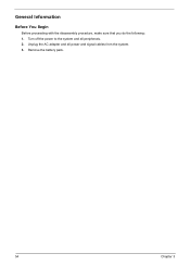
Remove the battery pack. 54 Chapter 3 Unplug the AC adapter and all peripherals. 2. Turn off the power to the system and all power and signal cables from the system. 3. General Information Before You Begin Before proceeding with the disassembly procedure, make sure that you do the following: 1.
Remove the battery pack. 54 Chapter 3 Unplug the AC adapter and all peripherals. 2. Turn off the power to the system and all power and signal cables from the system. 3. General Information Before You Begin Before proceeding with the disassembly procedure, make sure that you do the following: 1.
Aspire 7720 / 7720G Service Guide
Page 61
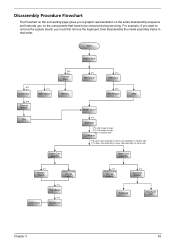
Start Battery Pack B*1 D*1 System Fan B*4 Thermal Module F*1 ODD Module CPU D*5 F*1 Thermal Door Memory Lower Case Assembly F*1 Mimi Cover F*2 HDD Door H*4 HDD Bracket HDD Middle Cover F*2 Keyboard C*2 LCD ...
Start Battery Pack B*1 D*1 System Fan B*4 Thermal Module F*1 ODD Module CPU D*5 F*1 Thermal Door Memory Lower Case Assembly F*1 Mimi Cover F*2 HDD Door H*4 HDD Bracket HDD Middle Cover F*2 Keyboard C*2 LCD ...
Aspire 7720 / 7720G Service Guide
Page 63
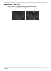
Unlock the battery lock (move the battery lock to the unlock position as shown). 2. Removing the Battery Pack 1. Chapter 3 57 Slide the battery release latch then remove the battery.
Unlock the battery lock (move the battery lock to the unlock position as shown). 2. Removing the Battery Pack 1. Chapter 3 57 Slide the battery release latch then remove the battery.
Aspire 7720 / 7720G Service Guide
Page 67
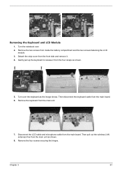
... the keyboard as the image shows. Detach the strip cover from the main board. Then pull out the wireless LAN antennas free from inside the battery compartment and the two screws fastening the LCD module. 3. Removing the Keyboard and LCD Module 1. Remove the two screws from the main unit as shown...
... the keyboard as the image shows. Detach the strip cover from the main board. Then pull out the wireless LAN antennas free from inside the battery compartment and the two screws fastening the LCD module. 3. Removing the Keyboard and LCD Module 1. Remove the two screws from the main unit as shown...

Aspire 7720 / 7720G Service Guide
Page 79
... errors might stop system operations, show error messages on the screen, or hang the system. 1. A loose connection can cause an error. Remove the battery pack. 2. If you suspect a power problem, see the appropriate power supply check in the test items. 3. then check that power is supplied. 3....power adapter and check that the DIMM is fully installed into the connector. NOTE: Make sure that power is supplied by the battery pack. Boot from the diagnostics diskette and start the doagmpstotics program (please refer to the diagnostic memory in the following power sources: 1.
... errors might stop system operations, show error messages on the screen, or hang the system. 1. A loose connection can cause an error. Remove the battery pack. 2. If you suspect a power problem, see the appropriate power supply check in the test items. 3. then check that power is supplied. 3....power adapter and check that the DIMM is fully installed into the connector. NOTE: Make sure that power is supplied by the battery pack. Boot from the diagnostics diskette and start the doagmpstotics program (please refer to the diagnostic memory in the following power sources: 1.
Aspire 7720 / 7720G Service Guide
Page 80
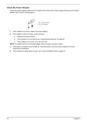
... power-on indicator does not light up, check the power cord of the power adapter cable. If the voltage is not corrected, see "Check the Battery Pack" on page 88. Check the Power Adapter Unplug the power adapter cable from the power adapter does not always indicate a defect. 3. NOTE: An audible...
... power-on indicator does not light up, check the power cord of the power adapter cable. If the voltage is not corrected, see "Check the Battery Pack" on page 88. Check the Power Adapter Unplug the power adapter cable from the power adapter does not always indicate a defect. 3. NOTE: An audible...

Aspire 7720 / 7720G Service Guide
Page 81
...the touchpad, the pointer drifts on recharging or discharging. In Power Meter, confirm that has less than 7.5 Vdc after recharging, replace the battery. Touchpad Check If the touchpad doesn't work, do the following: From Software: 1. This self-acting pointer movement can occur when a slight... hardware problem. No service actions are correct. 3. Chapter 4 75 Repeat the steps 1 and 2, for Current Power Source and Total Battery Power Remaining are necessary if the pointer movement stops in a short period of the total power remaining when installed in Control Panel 2. Remove ...
...the touchpad, the pointer drifts on recharging or discharging. In Power Meter, confirm that has less than 7.5 Vdc after recharging, replace the battery. Touchpad Check If the touchpad doesn't work, do the following: From Software: 1. This self-acting pointer movement can occur when a slight... hardware problem. No service actions are correct. 3. Chapter 4 75 Repeat the steps 1 and 2, for Current Power Source and Total Battery Power Remaining are necessary if the pointer movement stops in a short period of the total power remaining when installed in Control Panel 2. Remove ...

Aspire 7720 / 7720G Service Guide
Page 83
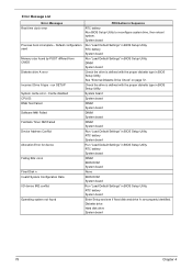
... Equipment Configuration Error Causes: 1. Error Message List Error Messages FRU/Action in BIOS Setup Utility. Replace and run Setup Replace RTC battery and Run BIOS Setup Utility to reconfigure system time, then reboot system. Unlock key switch Unlock external keyboard Monitor type does not... is dead - Keyboard error see "Keyboard or Auxiliary Input Device Check" on page 72. Keyboard locked - Default configuration used RTC battery Run BIOS Setup Utility to reconfigure system time, then reboot system. Hard disk drive System board Stuck Key see "Keyboard or Auxiliary Input...
... Equipment Configuration Error Causes: 1. Error Message List Error Messages FRU/Action in BIOS Setup Utility. Replace and run Setup Replace RTC battery and Run BIOS Setup Utility to reconfigure system time, then reboot system. Unlock key switch Unlock external keyboard Monitor type does not... is dead - Keyboard error see "Keyboard or Auxiliary Input Device Check" on page 72. Keyboard locked - Default configuration used RTC battery Run BIOS Setup Utility to reconfigure system time, then reboot system. Hard disk drive System board Stuck Key see "Keyboard or Auxiliary Input...
Aspire 7720 / 7720G Service Guide
Page 84
...are properly identified. Diskette drive Hard disk drive System board 78 Chapter 4 System board Run "Load Default Settings" in BIOS Setup Utility. RTC battery System board DIMM BIOS ROM System board None BIOS ROM System board Run "Load Default Settings" in BIOS Setup Utility. run SETUP System cache... error - RTC battery System board Run "Load Default Settings" in BIOS Setup Utility. Default configuration used Memory size found FRU/Action in BIOS Setup Utility See ...
...are properly identified. Diskette drive Hard disk drive System board 78 Chapter 4 System board Run "Load Default Settings" in BIOS Setup Utility. RTC battery System board DIMM BIOS ROM System board None BIOS ROM System board Run "Load Default Settings" in BIOS Setup Utility. run SETUP System cache... error - RTC battery System board Run "Load Default Settings" in BIOS Setup Utility. Default configuration used Memory size found FRU/Action in BIOS Setup Utility See ...
Aspire 7720 / 7720G Service Guide
Page 85
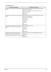
Power source (battery pack and power adapter). System board No beep during POST. Speaker System board Chapter 4 79 Error Message List No beep Error Messages FRU/Action in ... inverter ID LCD cable LCD inverter LCD System board No beep, power-on indicator turns on and a blinking cursor shown on page 73.. Power source (battery pack and power adapter). See "Power System Check" on LCD during POST but system runs correctly. LED board. Reconnect the LCD connectors. Ensure every connector...
Power source (battery pack and power adapter). System board No beep during POST. Speaker System board Chapter 4 79 Error Message List No beep Error Messages FRU/Action in ... inverter ID LCD cable LCD inverter LCD System board No beep, power-on indicator turns on and a blinking cursor shown on page 73.. Power source (battery pack and power adapter). See "Power System Check" on LCD during POST but system runs correctly. LED board. Reconnect the LCD connectors. Ensure every connector...

Aspire 7720 / 7720G Service Guide
Page 90
... LCD-Related Symptoms Symptom / Error LCD backlight doesn't work ). System board 84 Chapter 4 Battery pack Power adapter Hard drive & battery connection board System board Power source (battery pack and power adapter). Hold and press the power switch for more than 4 seconds. LCD...color displayed LCD has extra horizontal or vertical lines displayed. Battery pack Power adapter Hard drive & battery connection board System board Power source (battery pack and power adapter). Action in Sequence Power source (battery pack and power adapter). Reconnect the LCD connectors. See "...
... LCD-Related Symptoms Symptom / Error LCD backlight doesn't work ). System board 84 Chapter 4 Battery pack Power adapter Hard drive & battery connection board System board Power source (battery pack and power adapter). Hold and press the power switch for more than 4 seconds. LCD...color displayed LCD has extra horizontal or vertical lines displayed. Battery pack Power adapter Hard drive & battery connection board System board Power source (battery pack and power adapter). Action in Sequence Power source (battery pack and power adapter). Reconnect the LCD connectors. See "...

Aspire 7720 / 7720G Service Guide
Page 91
...'t be charged Action in Sequence See "Check the Battery Pack" on page 45. Action in Sequence See "Save to Disk (S4)" on page 75. LCD cover switch System board Chapter 4 85 The system doesn't ... Setup Utility to Disk (S4)" on page 45. Hard disk connection board Hard disk drive System board See "Save to Disk (S4)" on page 45. Battery pack System board PCMCIA-Related Symptoms Symptom / Error System cannot detect the PC Card (PCMCIA) PCMCIA slot pin is from the keyboard) Hard disk drive...
...'t be charged Action in Sequence See "Check the Battery Pack" on page 45. Action in Sequence See "Save to Disk (S4)" on page 75. LCD cover switch System board Chapter 4 85 The system doesn't ... Setup Utility to Disk (S4)" on page 45. Hard disk connection board Hard disk drive System board See "Save to Disk (S4)" on page 45. Battery pack System board PCMCIA-Related Symptoms Symptom / Error System cannot detect the PC Card (PCMCIA) PCMCIA slot pin is from the keyboard) Hard disk drive...


