Aspire 7720 / 7720G Service Guide
Page 17
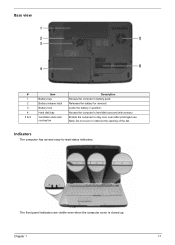
Note: Do not cover or obstruct the opening of the fan. The front panel indicators are visible even when the computer cover is closed up. Chapter 1 11 Indicators The computer has several easy-to stay cool, even after prolonged use. Houses the computer's hard disk (secured with screws) Enable the computer to -read status indicators. Base view # 1 2 3 4 5 & 6 Item Battery bay Battery release latch Battery lock Hard disk bay Ventilation slots and cooling fan Description Houses the computer's battery pack. Releases the battery for removal. Locks the battery in position.
Note: Do not cover or obstruct the opening of the fan. The front panel indicators are visible even when the computer cover is closed up. Chapter 1 11 Indicators The computer has several easy-to stay cool, even after prolonged use. Houses the computer's hard disk (secured with screws) Enable the computer to -read status indicators. Base view # 1 2 3 4 5 & 6 Item Battery bay Battery release latch Battery lock Hard disk bay Ventilation slots and cooling fan Description Houses the computer's battery pack. Releases the battery for removal. Locks the battery in position.

Aspire 7720 / 7720G Service Guide
Page 36
... FSB) or higher Intel® 965PM/965GM Express chipset+ICH8M Intel socket 1466pin FCBGA 0.944~1.3V CPU Fan True Value Table CPU Temperature Core 0 86 88 91 95 TEST Condition: 35W@Ambient 35 degree C Fan Speed Core 1 (rpm) 86 3700 88 3450 91 3150 95 2800 Acoustic Level (dBA) 39 36.5 34...
... FSB) or higher Intel® 965PM/965GM Express chipset+ICH8M Intel socket 1466pin FCBGA 0.944~1.3V CPU Fan True Value Table CPU Temperature Core 0 86 88 91 95 TEST Condition: 35W@Ambient 35 degree C Fan Speed Core 1 (rpm) 86 3700 88 3450 91 3150 95 2800 Acoustic Level (dBA) 39 36.5 34...
Aspire 7720 / 7720G Service Guide
Page 61
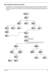
... (for AS models) Lower Case F*1 Main Board F*2 Speaker Set F*2 Media Board (for AS models) F*1 Touchpad Bracket Touchpad Touchpad FFC Chapter 3 55 Start Battery Pack B*1 D*1 System Fan B*4 Thermal Module F*1 ODD Module CPU D*5 F*1 Thermal Door Memory Lower Case Assembly F*1 Mimi Cover F*2 HDD Door H*4 HDD Bracket HDD Middle Cover F*2 Keyboard C*2 LCD hinges to logic...
... (for AS models) Lower Case F*1 Main Board F*2 Speaker Set F*2 Media Board (for AS models) F*1 Touchpad Bracket Touchpad Touchpad FFC Chapter 3 55 Start Battery Pack B*1 D*1 System Fan B*4 Thermal Module F*1 ODD Module CPU D*5 F*1 Thermal Door Memory Lower Case Assembly F*1 Mimi Cover F*2 HDD Door H*4 HDD Bracket HDD Middle Cover F*2 Keyboard C*2 LCD hinges to logic...

Aspire 7720 / 7720G Service Guide
Page 64
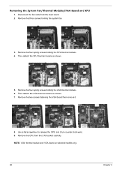
... to remove the HDD module in the direction of the arrow. Removing the HDD Module/Memory/Wireless LAN Card/Modem Card/ TV Tuner Card/System Fan/Thermal Modules/VGA Board/CPU/ Keyboard and the LCD Module Removing the HDD Module 1. Detach the thermal cover from the main unit. 3. Remove the four...
... to remove the HDD module in the direction of the arrow. Removing the HDD Module/Memory/Wireless LAN Card/Modem Card/ TV Tuner Card/System Fan/Thermal Modules/VGA Board/CPU/ Keyboard and the LCD Module Removing the HDD Module 1. Detach the thermal cover from the main unit. 3. Remove the four...
Aspire 7720 / 7720G Service Guide
Page 66
.... Then detach the VGA thermal module as shown. 5. Remove the CPU from the main board. 2. Removing the System Fan/Thermal Modules/VGA Board and CPU 1. Remove the four spring screws holding the system fan. 3. NOTE: VGA thermal module and VGA board on selected models only. 60 Chapter 3 Remove the three screws holding...
.... Then detach the VGA thermal module as shown. 5. Remove the CPU from the main board. 2. Removing the System Fan/Thermal Modules/VGA Board and CPU 1. Remove the four spring screws holding the system fan. 3. NOTE: VGA thermal module and VGA board on selected models only. 60 Chapter 3 Remove the three screws holding...
Aspire 7720 Series User's Guide EN
Page 40
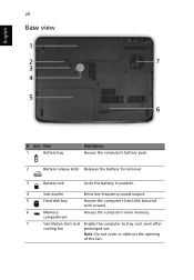
Note: Do not cover or obstruct the opening of the fan. English 20 Base view 1 2 6 3 4 5 # Icon Item 1 Battery bay Description Houses the computer's battery pack. 2 Battery release latch Releases the battery for removal. 3 Battery lock Locks the battery in position. 4 Sub woofer Emits low frequency sound output. 5 Hard disk bay Houses the computer's hard disk (secured with screws). 6 Memory compartment Houses the computer's main memory. 7 Ventilation slots and Enable the computer to stay cool, even after cooling fan prolonged use.
Note: Do not cover or obstruct the opening of the fan. English 20 Base view 1 2 6 3 4 5 # Icon Item 1 Battery bay Description Houses the computer's battery pack. 2 Battery release latch Releases the battery for removal. 3 Battery lock Locks the battery in position. 4 Sub woofer Emits low frequency sound output. 5 Hard disk bay Houses the computer's hard disk (secured with screws). 6 Memory compartment Houses the computer's main memory. 7 Ventilation slots and Enable the computer to stay cool, even after cooling fan prolonged use.


