
Aspire 7720 / 7720G Service Guide
Page 7
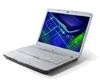
.../677 MHz memory, upgradeable to 4GB using two soDIMM modules (dual-channel support) Display and graphics T 17" WXGA+ high-brightness Acer CrystalBriteTM TFT LCD, 1680 x 1050 pixel resolution, 6 lamps T 16 ms typical of the computer's many features: Operating system T Genuine Windows®... Specifications Features Below is a brief summary of /off and 8 ms average gray-to-gray response time T Simultaneous multi-window viewing via Acer VistaTM supported T Supporting NVIDIA® PureVideoTM technology (WMV HD, High-Definition MPEG-2 Hardware Acceleration, integrated HDTV encoder) dual-link DVI, ...
.../677 MHz memory, upgradeable to 4GB using two soDIMM modules (dual-channel support) Display and graphics T 17" WXGA+ high-brightness Acer CrystalBriteTM TFT LCD, 1680 x 1050 pixel resolution, 6 lamps T 16 ms typical of the computer's many features: Operating system T Genuine Windows®... Specifications Features Below is a brief summary of /off and 8 ms average gray-to-gray response time T Simultaneous multi-window viewing via Acer VistaTM supported T Supporting NVIDIA® PureVideoTM technology (WMV HD, High-Definition MPEG-2 Hardware Acceleration, integrated HDTV encoder) dual-link DVI, ...
Aspire 7720 / 7720G Service Guide
Page 11
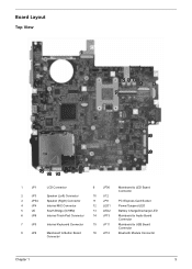
Board Layout Top View 1 5 6 23 4 8 9 7 10 15 11 16 12 13 14 1 JP1 LCD Connector 9 JP36 Mainboard to LED Board Connector 2 JP3 Speaker (Left) Connector 10 U12 3 JP34 Speaker (Right) Connector 11 JP9 PCI Express Card Socket 4 JP4 Internal ...
Board Layout Top View 1 5 6 23 4 8 9 7 10 15 11 16 12 13 14 1 JP1 LCD Connector 9 JP36 Mainboard to LED Board Connector 2 JP3 Speaker (Left) Connector 10 U12 3 JP34 Speaker (Right) Connector 11 JP9 PCI Express Card Socket 4 JP4 Internal ...
Aspire 7720 / 7720G Service Guide
Page 14
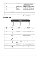
Comfortable support area for sound recording. support 6 LCD display latch Secures the LCD display in jack Accepts input from external microphones. 5 Headphones/speaker/ Connects to show the status of the computer's functions... Microphone-in place when closed. 7 Infrared port Interfaces with S/PDIF speakers, headphones). Launches the Empowering Technology toolbar. Also called Liquid-Crystal Display (LCD), displays computer output. infrared printer and IR-aware computer). 8 Chapter 1 Left and right speakers deliver stereo audio output. The left and right buttons...
Comfortable support area for sound recording. support 6 LCD display latch Secures the LCD display in jack Accepts input from external microphones. 5 Headphones/speaker/ Connects to show the status of the computer's functions... Microphone-in place when closed. 7 Infrared port Interfaces with S/PDIF speakers, headphones). Launches the Empowering Technology toolbar. Also called Liquid-Crystal Display (LCD), displays computer output. infrared printer and IR-aware computer). 8 Chapter 1 Left and right speakers deliver stereo audio output. The left and right buttons...
Aspire 7720 / 7720G Service Guide
Page 15
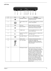
... 1 9 Left View # Icon Item Description 1 Kensington lock slot Connects to a Kensington-compatible computer security lock. 2 External display (VGA) Connects to a display device (e.g., external port monitor, LCD projector). 3 DVI DVI-D port Supports digital video connections. 4 Ethernet (RJ-45) Connects to IEEE 1394 devices. 8 Volume control Increases and decreases the volume. 9 5-in 75x54mm...
... 1 9 Left View # Icon Item Description 1 Kensington lock slot Connects to a Kensington-compatible computer security lock. 2 External display (VGA) Connects to a display device (e.g., external port monitor, LCD projector). 3 DVI DVI-D port Supports digital video connections. 4 Ethernet (RJ-45) Connects to IEEE 1394 devices. 8 Volume control Increases and decreases the volume. 9 5-in 75x54mm...

Aspire 7720 / 7720G Service Guide
Page 26
...You can also define the power plan optimized for the newly created power plan. 3. To create new power plan 1. You can adjust CPU speed, LCD brightness and other settings, or click on buttons to apply the setting. 6. Balanced, Power Saver, and High Performance. Click "OK" to turn the... CardBus, FireWire (1394), Wired LAN and Optical Device if supported. Change the display and sleep settings as desired. 5. To launch it, select Acer ePower Management from the Empowering Technology interface. Acer ePower Management Acer ePower Management features a straightforward user interface.
...You can also define the power plan optimized for the newly created power plan. 3. To create new power plan 1. You can adjust CPU speed, LCD brightness and other settings, or click on buttons to apply the setting. 6. Balanced, Power Saver, and High Performance. Click "OK" to turn the... CardBus, FireWire (1394), Wired LAN and Optical Device if supported. Change the display and sleep settings as desired. 5. To launch it, select Acer ePower Management from the Empowering Technology interface. Acer ePower Management Acer ePower Management features a straightforward user interface.
Aspire 7720 / 7720G Service Guide
Page 42
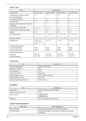
All devices in the system are turned off completely. Chapter 1 OS initiated shutdown. LCD 17" inch Item Display Mode Typical White Luminance (cd/m2) also called Brightness Luminance Uniformity Contrast Ratio Response Time (Optical Rise Time/Fall Time)msec ... to +60 Normally White 300 70 250 8 3.3V N/A 600 317.3x242.0x6. 5 1 channel LVDS 262,144 40/40 20/40 0 to +50 -20 to +60 LCD Inverter Item Vendor & model name Brightness conditions Input voltage (V) Input current (mA) Output voltage (V, rms) Output current (mA, rms) Output voltage frequency (k Hz) Specification Darfon...
All devices in the system are turned off completely. Chapter 1 OS initiated shutdown. LCD 17" inch Item Display Mode Typical White Luminance (cd/m2) also called Brightness Luminance Uniformity Contrast Ratio Response Time (Optical Rise Time/Fall Time)msec ... to +60 Normally White 300 70 250 8 3.3V N/A 600 317.3x242.0x6. 5 1 channel LVDS 262,144 40/40 20/40 0 to +50 -20 to +60 LCD Inverter Item Vendor & model name Brightness conditions Input voltage (V) Input current (mA) Output voltage (V, rms) Output current (mA, rms) Output voltage frequency (k Hz) Specification Darfon...
Aspire 7720 / 7720G Service Guide
Page 61
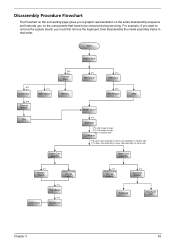
... Module F*1 ODD Module CPU D*5 F*1 Thermal Door Memory Lower Case Assembly F*1 Mimi Cover F*2 HDD Door H*4 HDD Bracket HDD Middle Cover F*2 Keyboard C*2 LCD hinges to logic D*2 LCD hinges to logic C*2 on bottom side LCD Module C*8 upper case assembly to lower case assembly on bottom side C*2 upper case assembly to lower case assembly on upper side...
... Module F*1 ODD Module CPU D*5 F*1 Thermal Door Memory Lower Case Assembly F*1 Mimi Cover F*2 HDD Door H*4 HDD Bracket HDD Middle Cover F*2 Keyboard C*2 LCD hinges to logic D*2 LCD hinges to logic C*2 on bottom side LCD Module C*8 upper case assembly to lower case assembly on bottom side C*2 upper case assembly to lower case assembly on upper side...

Aspire 7720 / 7720G Service Guide
Page 64
... the arrow. Removing the HDD Module/Memory/Wireless LAN Card/Modem Card/ TV Tuner Card/System Fan/Thermal Modules/VGA Board/CPU/ Keyboard and the LCD Module Removing the HDD Module 1. Detach the HDD cover from the DIMM socket then remove it (If the notebook has two memory, then repeat this...
... the arrow. Removing the HDD Module/Memory/Wireless LAN Card/Modem Card/ TV Tuner Card/System Fan/Thermal Modules/VGA Board/CPU/ Keyboard and the LCD Module Removing the HDD Module 1. Detach the HDD cover from the DIMM socket then remove it (If the notebook has two memory, then repeat this...
Aspire 7720 / 7720G Service Guide
Page 67
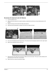
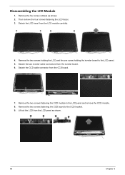
... and microphone cable from the front side and remove it from inside the battery compartment and the two screws fastening the LCD module. 3. Remove the four screws securing the hinges. Turn over . 2. Gently pull up the keyboard to release it . 4. Chapter 3 61 Remove the two screws from ... cable from the main unit. 7. Then pull out the wireless LAN antennas free from the main unit as the image shows. Removing the Keyboard and LCD Module 1. Turn the notebook over the keyboard as shown. 8.
... and microphone cable from the front side and remove it from inside the battery compartment and the two screws fastening the LCD module. 3. Remove the four screws securing the hinges. Turn over . 2. Gently pull up the keyboard to release it . 4. Chapter 3 61 Remove the two screws from ... cable from the main unit. 7. Then pull out the wireless LAN antennas free from the main unit as the image shows. Removing the Keyboard and LCD Module 1. Turn the notebook over the keyboard as shown. 8.
Aspire 7720 / 7720G Service Guide
Page 68
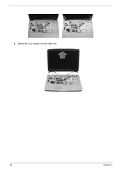
Detach the LCD module from the main unit. 62 Chapter 3 9.
Detach the LCD module from the main unit. 62 Chapter 3 9.
Aspire 7720 / 7720G Service Guide
Page 74
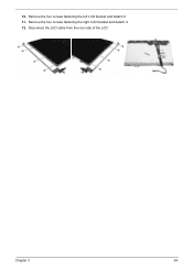
...two screws fastening the CCD board to the LCD panel and remove the CCD module. 8. Detach the LCD bezel from the inverter board. 6. Remove the two screws fastening the CCD module to the CCD bracket. 9. Remove the two screws holding the LCD and the one screw holding the inverter ...board to the LCD panel. 5. Detach the two inverter cable connectors from the LCD module carefully. 4. Disassembling the LCD Module 1. Lift out the LCD from the CCD board. 7. Then remove the four screws ...
...two screws fastening the CCD board to the LCD panel and remove the CCD module. 8. Detach the LCD bezel from the inverter board. 6. Remove the two screws fastening the CCD module to the CCD bracket. 9. Remove the two screws holding the LCD and the one screw holding the inverter ...board to the LCD panel. 5. Detach the two inverter cable connectors from the LCD module carefully. 4. Disassembling the LCD Module 1. Lift out the LCD from the CCD board. 7. Then remove the four screws ...
Aspire 7720 / 7720G Service Guide
Page 75
Disconnect the LCD cable from the rear side of the LCD. Remove the four screws fastening the right LCD bracket and detach it . 11. 10. Chapter 3 69 Remove the four screws fastening the left LCD bracket and detach it . 12.
Disconnect the LCD cable from the rear side of the LCD. Remove the four screws fastening the right LCD bracket and detach it . 11. 10. Chapter 3 69 Remove the four screws fastening the left LCD bracket and detach it . 12.

Aspire 7720 / 7720G Service Guide
Page 77
... to re-create the failure by running the diagnostic test or by repeating the same operation. 3. POST does not complete. Non-Acer products, prototype cards, or modified options can give false errors and invalid system responses. 1. Use the following procedure as possible. 2.... No beep or error codes are intended to test only Acer products. POST detects an error and displayed messages on ). Symptoms cannot be re-created (intermittent problems). LCD display problems or others). Other symptoms (i.e. Go To "Power System Check" on page ...
... to re-create the failure by running the diagnostic test or by repeating the same operation. 3. POST does not complete. Non-Acer products, prototype cards, or modified options can give false errors and invalid system responses. 1. Use the following procedure as possible. 2.... No beep or error codes are intended to test only Acer products. POST detects an error and displayed messages on ). Symptoms cannot be re-created (intermittent problems). LCD display problems or others). Other symptoms (i.e. Go To "Power System Check" on page ...
Aspire 7720 / 7720G Service Guide
Page 85
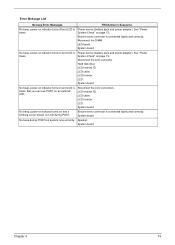
... DIMM. No beep, power-on indicator turns on and LCD is blank. System board. Reconnect the LCD connector Hard disk drive LCD inverter ID LCD cable LCD Inverter LCD System board No beep, power-on indicator turns on and LCD is blank. LED board. LCD inverter ID LCD cable LCD inverter LCD System board No beep, power-on indicator turns on...
... DIMM. No beep, power-on indicator turns on and LCD is blank. System board. Reconnect the LCD connector Hard disk drive LCD inverter ID LCD cable LCD Inverter LCD System board No beep, power-on indicator turns on and LCD is blank. LED board. LCD inverter ID LCD cable LCD inverter LCD System board No beep, power-on indicator turns on...

Aspire 7720 / 7720G Service Guide
Page 90
... Power shuts down during operation The system doesn't power-on page 73. System board 84 Chapter 4 LCD inverter ID LCD cable LCD inverter LCD System board Reconnect the LCD connector LCD inverter ID LCD cable LCD inverter LCD System board LCD inverter ID LCD inverter LCD cable LCD System board Indicator-Related Symptoms Symptom / Error Action in characters Abnormal screen Wrong color displayed...
... Power shuts down during operation The system doesn't power-on page 73. System board 84 Chapter 4 LCD inverter ID LCD cable LCD inverter LCD System board Reconnect the LCD connector LCD inverter ID LCD cable LCD inverter LCD System board LCD inverter ID LCD inverter LCD cable LCD System board Indicator-Related Symptoms Symptom / Error Action in characters Abnormal screen Wrong color displayed...

Aspire 7720 / 7720G Service Guide
Page 91
... no sound. The system doesn't resume from standby mode after closing the LCD The system doesn't resume from actual size. LCD cover switch System board See "Save to Disk (S4)" on page 75. LCD cover switch System board Chapter 4 85 Action in Sequence PCMCIA slot assembly System...Memory-Related Symptoms Symptom / Error Memory count (size) appears different from hibernation mode. The system doesn't enter standby mode after opening the LCD. Power-Related Symptoms Symptom / Error Battery can't be charged Action in Sequence See "Check the Battery Pack" on page 45. Hard ...
... no sound. The system doesn't resume from standby mode after closing the LCD The system doesn't resume from actual size. LCD cover switch System board See "Save to Disk (S4)" on page 75. LCD cover switch System board Chapter 4 85 Action in Sequence PCMCIA slot assembly System...Memory-Related Symptoms Symptom / Error Memory count (size) appears different from hibernation mode. The system doesn't enter standby mode after opening the LCD. Power-Related Symptoms Symptom / Error Battery can't be charged Action in Sequence See "Check the Battery Pack" on page 45. Hard ...

Aspire 7720 / 7720G Service Guide
Page 92
... board System board Peripheral-Related Symptoms Symptom / Error System configuration does not match the installed devices. External display does not work correctly. Press Fn+F5, LCD/CRT/Both display switching System board System board Ensure the "Parallel Port" in this list and the problem remains, see "Undetermined Problems" on page 88...
... board System board Peripheral-Related Symptoms Symptom / Error System configuration does not match the installed devices. External display does not work correctly. Press Fn+F5, LCD/CRT/Both display switching System board System board Ensure the "Parallel Port" in this list and the problem remains, see "Undetermined Problems" on page 88...

Aspire 7720 / 7720G Service Guide
Page 94
... at a time until you find the failing FRU. 7. If the problem remains, replace the following FRU one at the time of the following devices: T Non-Acer devices T Printer, mouse, and other external devices T Battery pack T Hard disk drive T DIMM T CD-ROM/Diskette drive Module T PC Cards 4. If any problems are found...
... at a time until you find the failing FRU. 7. If the problem remains, replace the following FRU one at the time of the following devices: T Non-Acer devices T Printer, mouse, and other external devices T Battery pack T Hard disk drive T DIMM T CD-ROM/Diskette drive Module T PC Cards 4. If any problems are found...
Aspire 7720 / 7720G Service Guide
Page 95
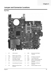
Jumper and Connector Locations Top View 1 Chapter 5 5 6 23 4 8 9 7 10 15 11 16 12 13 14 1 JP1 LCD Connector 9 JP36 Mainboard to LED Board Connector 2 JP3 Speaker (Left) Connector 10 U12 3 JP34 Speaker (Right) Connector 11 JP9 PCI Express Card Socket 4 JP4 Internal ...
Jumper and Connector Locations Top View 1 Chapter 5 5 6 23 4 8 9 7 10 15 11 16 12 13 14 1 JP1 LCD Connector 9 JP36 Mainboard to LED Board Connector 2 JP3 Speaker (Left) Connector 10 U12 3 JP34 Speaker (Right) Connector 11 JP9 PCI Express Card Socket 4 JP4 Internal ...
Aspire 7720 / 7720G Service Guide
Page 106
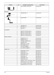
Category SPEAKER No. AS7720 LCD SCREW PAD 17 LCD SIDE RUBBER 17 LCD FRONT RUBBER 17 47.AHJ02.004 47.AHJ02.005 47.AHJ02.006 47.AHJ02.007 40.AHJ02.001 47.AHJ02.001 47.AHJ02.002 47.....005 CPU THERMAL SCREW ASSY 86.AHJ02.006 SCREW,M M 2.0D 3L K 5D NI + 86.AHE02.008 Chapter 6 Part Name and Description VGA THERMAL (M71M) DIS Acer Part No. 60.AHK02.003 SPEAKER R&L 17 SUB WOOFER 23.AHJ02.002 23.AHJ02.003 ACCESSORY MISCELLANEOUS SCREW LIST 100 ANTENNA R 17 ANTENNA L 17 MIC...
Category SPEAKER No. AS7720 LCD SCREW PAD 17 LCD SIDE RUBBER 17 LCD FRONT RUBBER 17 47.AHJ02.004 47.AHJ02.005 47.AHJ02.006 47.AHJ02.007 40.AHJ02.001 47.AHJ02.001 47.AHJ02.002 47.....005 CPU THERMAL SCREW ASSY 86.AHJ02.006 SCREW,M M 2.0D 3L K 5D NI + 86.AHE02.008 Chapter 6 Part Name and Description VGA THERMAL (M71M) DIS Acer Part No. 60.AHK02.003 SPEAKER R&L 17 SUB WOOFER 23.AHJ02.002 23.AHJ02.003 ACCESSORY MISCELLANEOUS SCREW LIST 100 ANTENNA R 17 ANTENNA L 17 MIC...


