
Service Guide
Page 7
... VGA Card Removing the TV Card Removing the Mode Card Removing the Hard Disk Drive Removing the Front Bezel Removing the Rear USB Board Removing the Cables Removing the System Fan Removing the Optical Drive Removing the Power Supply Removing the Memory Modules Removing the Removable HDD bay Removing the Mainboard 26 26 27 28 29 30 31 32 33 35 36 37 38 39 40 41 42 43 45 System Troubleshooting Hardware Diagnostic Procedure System Check Procedures Power System Check System External Inspection System Internal Inspection Beep Codes Checkpoints BIOS Recovery...
... VGA Card Removing the TV Card Removing the Mode Card Removing the Hard Disk Drive Removing the Front Bezel Removing the Rear USB Board Removing the Cables Removing the System Fan Removing the Optical Drive Removing the Power Supply Removing the Memory Modules Removing the Removable HDD bay Removing the Mainboard 26 26 27 28 29 30 31 32 33 35 36 37 38 39 40 41 42 43 45 System Troubleshooting Hardware Diagnostic Procedure System Check Procedures Power System Check System External Inspection System Internal Inspection Beep Codes Checkpoints BIOS Recovery...
Service Guide
Page 10
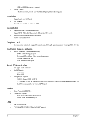
...to support for double slot, full length graphics cards in the single PSIe X16 slot On-Board Graphic solution • Intel HD Graphics (Clarkdale series CPU) DVMT 5.0 technology support Enhanced 3D and Clear Video technology support 1 D-sub VGA port on rear Dual View function support Serial ATA controller • • Slot Type: SATA connector Six SATA ports: • • 4 for HDD 2 for ODD 1.HDD : Support RAID 0/1/5/10 2.CD-ROM/CD-RW/DVD-ROM/DVD-RW/DVD+RW/DVD Dual/DVD SuperMultiPlus/Blu-Ray ODD 3.AHCI mode supported for internal SATA port • Storage Type support: Audio...
...to support for double slot, full length graphics cards in the single PSIe X16 slot On-Board Graphic solution • Intel HD Graphics (Clarkdale series CPU) DVMT 5.0 technology support Enhanced 3D and Clear Video technology support 1 D-sub VGA port on rear Dual View function support Serial ATA controller • • Slot Type: SATA connector Six SATA ports: • • 4 for HDD 2 for ODD 1.HDD : Support RAID 0/1/5/10 2.CD-ROM/CD-RW/DVD-ROM/DVD-RW/DVD+RW/DVD Dual/DVD SuperMultiPlus/Blu-Ray ODD 3.AHCI mode supported for internal SATA port • Storage Type support: Audio...

Service Guide
Page 11
... x 16 slot Support two PCIe x 1 slots Support one PCI slot Total I/O ports 1 PS/2 Keyboard port, 1 PS/2 Mouse port 1 D-Sub VGA port 1 RJ45 LAN port 6 USB ports 3 ports Audio jack One HD headphone output in front bezel One MIC-IN in front bezel 4 * USB H5X2 Header (support 8 ports) 1 * Front Audio Pannel H5X2 header 1 * Front Panel IO H7X2 Header for Acer pin define 1 * H1X4 CPU with SAMRT FAN controller 1 * H1X3 System with SAMRT FAN controller 1 * H1X4 SPDIFOUT Header for Acer pin define 1 * H3X1 Clear CMOS Header (with jumper...
... x 16 slot Support two PCIe x 1 slots Support one PCI slot Total I/O ports 1 PS/2 Keyboard port, 1 PS/2 Mouse port 1 D-Sub VGA port 1 RJ45 LAN port 6 USB ports 3 ports Audio jack One HD headphone output in front bezel One MIC-IN in front bezel 4 * USB H5X2 Header (support 8 ports) 1 * Front Audio Pannel H5X2 header 1 * Front Panel IO H7X2 Header for Acer pin define 1 * H1X4 CPU with SAMRT FAN controller 1 * H1X3 System with SAMRT FAN controller 1 * H1X4 SPDIFOUT Header for Acer pin define 1 * H3X1 Clear CMOS Header (with jumper...

Service Guide
Page 15
... Audio controller LAN controller HDD controller Specification PCH: Intel H57 Realtek ALC662VC-0 REALTEK RTL8111E Giga LAN(ASF suport) PCH: Intel H57 Chapter 1 7 Hardware Specifications and Configurations Processor Item Processor Type Socket Type Minimum operating speed Specification CPUs which complaint with Intel FSB 800/1066/1333 MHz CPUs Intel Socket T LGA 1156 pin 0 MHz (If Stop CPU Clock in Sleep State in BIOS Setup is set to Enabled.) BIOS Item BIOS code programer BIOS version BIOS ROM type BIOS ROM size Support protocol Device Boot Support Specification AMI Kernel with Acer...
... Audio controller LAN controller HDD controller Specification PCH: Intel H57 Realtek ALC662VC-0 REALTEK RTL8111E Giga LAN(ASF suport) PCH: Intel H57 Chapter 1 7 Hardware Specifications and Configurations Processor Item Processor Type Socket Type Minimum operating speed Specification CPUs which complaint with Intel FSB 800/1066/1333 MHz CPUs Intel Socket T LGA 1156 pin 0 MHz (If Stop CPU Clock in Sleep State in BIOS Setup is set to Enabled.) BIOS Item BIOS code programer BIOS version BIOS ROM type BIOS ROM size Support protocol Device Boot Support Specification AMI Kernel with Acer...

Service Guide
Page 16
... ~4GB 1G ~4GB 1G ~4GB 1G ~4GB 1G~16GB Maximum System Memory Supported System Memory Item Memory slot number Support Memory size per socket Support memory type Support memory interface Support memory voltage Support memory module package Support to parity check feature Specification 4 slot 1GB/2GB/4GB DDRIII DDRIII 1066/1333 1.5V 240-pin DDRIII Yes Support to error correction code (ECC) feature No Memory module combinations You can install memory modules in any other HDA compatible audio controller.
... ~4GB 1G ~4GB 1G ~4GB 1G ~4GB 1G~16GB Maximum System Memory Supported System Memory Item Memory slot number Support Memory size per socket Support memory type Support memory interface Support memory voltage Support memory module package Support to parity check feature Specification 4 slot 1GB/2GB/4GB DDRIII DDRIII 1066/1333 1.5V 240-pin DDRIII Yes Support to error correction code (ECC) feature No Memory module combinations You can install memory modules in any other HDA compatible audio controller.

Service Guide
Page 18
... support. Hard Disk drive goes into power saving mode. Hard disk drive goes into Standby mode(for Windows. LED on panel turns amber colour. Resume method: Resume to original state by pushing external switch Button,modem ring in,keyboard an mouse for APM mode Return to original state by pushing external switch Button,modem ring in and USB keyboard for ATA standard interface). Resume recovery time 3-5sec Global Standby Mode Global power management timer(2-120minutes,time step=10minute). On board device power management support. Disable...
... support. Hard Disk drive goes into power saving mode. Hard disk drive goes into Standby mode(for Windows. LED on panel turns amber colour. Resume method: Resume to original state by pushing external switch Button,modem ring in,keyboard an mouse for APM mode Return to original state by pushing external switch Button,modem ring in and USB keyboard for ATA standard interface). Resume recovery time 3-5sec Global Standby Mode Global power management timer(2-120minutes,time step=10minute). On board device power management support. Disable...

Service Guide
Page 19
... Utilities CMOS Setup Utility CMOS setup is a hardware configuration program built into the system ROM, called CMOS RAM. NOTE: CMOS Setup Utility will need to as "BIOS", "Setup", or "Setup utility" in CMOS. When changing the system configuration settings When redefining the communication ports to prevent any conflicts When modifying the power management configuration When changing the password or making other changes to make sure that you close the Setup. The system reboots immediately after you have saved all open files. Chapter 2 11 CMOS setup loads the configuration...
... Utilities CMOS Setup Utility CMOS setup is a hardware configuration program built into the system ROM, called CMOS RAM. NOTE: CMOS Setup Utility will need to as "BIOS", "Setup", or "Setup utility" in CMOS. When changing the system configuration settings When redefining the communication ports to prevent any conflicts When modifying the power management configuration When changing the password or making other changes to make sure that you close the Setup. The system reboots immediately after you have saved all open files. Chapter 2 11 CMOS setup loads the configuration...

Service Guide
Page 22
... system memory installed on the system. Serial number of the system. Product Information The Product Information menu displays basic information about the system. Product name of the system. These entries are for your reference only and are not user-configurable. Parameter Processor Type Processor Speed System Memory Product Name System Serial Number System BIOS Version BIOS Release Date Asset Tag Number Description Type of the CPU installed on the system. Speed of CPU installed...
... system memory installed on the system. Serial number of the system. Product Information The Product Information menu displays basic information about the system. Product name of the system. These entries are for your reference only and are not user-configurable. Parameter Processor Type Processor Speed System Memory Product Name System Serial Number System BIOS Version BIOS Release Date Asset Tag Number Description Type of the CPU installed on the system. Speed of CPU installed...

Service Guide
Page 24
... disabled, the diagnostic screen displays during startup. Enables or disables BIOS to access the Hard Disk Drive Priority submenu and specify the boot device priority sequence from available hard drives. Option Enabled Disabled Enabled Disabled Hard Disk CD^DVD Removable Device LAN Hard Disk Drive Priority Optical Disk Drives Priority Removable Device Priority Bootup Num-Lock USB Beep Message Press Enter to display error beeps or messages during USB device enumeration. Press Enter to boot the computer by shortening or skipping certain standard booting process. On Off Disabled Enabled...
... disabled, the diagnostic screen displays during startup. Enables or disables BIOS to access the Hard Disk Drive Priority submenu and specify the boot device priority sequence from available hard drives. Option Enabled Disabled Enabled Disabled Hard Disk CD^DVD Removable Device LAN Hard Disk Drive Priority Optical Disk Drives Priority Removable Device Priority Bootup Num-Lock USB Beep Message Press Enter to display error beeps or messages during USB device enumeration. Press Enter to boot the computer by shortening or skipping certain standard booting process. On Off Disabled Enabled...

Service Guide
Page 26
... Parameter Onboard SATA Controller Onboard SATA Mode Onboard USB Controller Legacy USB Support USB Storage Emulation Onboard Audio Controller Onboard LAN Controller Onboard LAN Option ROM Description Enables or disables the onboard SATA controller. Enables or disables support for onboard network controller. Enables or disables the load of embedded option ROM for legacy USB devices. Option Enabled Disabled RAID Native IDE Enabled Disabled Enabled Disabled Enabled Disabled Enabled Disabled Enabled Disabled Enabled Disabled 18 Chapter 2 Enables or disables the onboard USB controller.
... Parameter Onboard SATA Controller Onboard SATA Mode Onboard USB Controller Legacy USB Support USB Storage Emulation Onboard Audio Controller Onboard LAN Controller Onboard LAN Option ROM Description Enables or disables the onboard SATA controller. Enables or disables support for onboard network controller. Enables or disables the load of embedded option ROM for legacy USB devices. Option Enabled Disabled RAID Native IDE Enabled Disabled Enabled Disabled Enabled Disabled Enabled Disabled Enabled Disabled Enabled Disabled 18 Chapter 2 Enables or disables the onboard USB controller.

Service Guide
Page 54
Refer to "Power System check" and "Beep Codes" to determine which corrective action to recreate the failure by running the diagnostic tests or repeating thesame operation. Verify the symptoms by attempting to perform. Chapter 4 46 Chapter 4 System Troubleshooting This chapter provides instructions on how to troubleshoot system hardware problems. Hardware Diagnostic Procedure IMPORTANT:The diagnostic tests described in as much detail as possible. NonAcerproducts, prototype cards, or modified options can...
Refer to "Power System check" and "Beep Codes" to determine which corrective action to recreate the failure by running the diagnostic tests or repeating thesame operation. Verify the symptoms by attempting to perform. Chapter 4 46 Chapter 4 System Troubleshooting This chapter provides instructions on how to troubleshoot system hardware problems. Hardware Diagnostic Procedure IMPORTANT:The diagnostic tests described in as much detail as possible. NonAcerproducts, prototype cards, or modified options can...

Service Guide
Page 55
... the power outlets. Verify that all cable connectors inside the system are firmly and correctly attached to the system and AC source. System External Inspection 1. 2. 3. 4. Remove the system covers.For instructions on the front panel, which can try viewing the POST messages and BIOS event logs during the system startup. 47 Chapter 4 Verify that components are Acer-qualified and supported. 10. Replace the system covers...
... the power outlets. Verify that all cable connectors inside the system are firmly and correctly attached to the system and AC source. System External Inspection 1. 2. 3. 4. Remove the system covers.For instructions on the front panel, which can try viewing the POST messages and BIOS event logs during the system startup. 47 Chapter 4 Verify that components are Acer-qualified and supported. 10. Replace the system covers...

Service Guide
Page 56
.... BIOS damaged. Graphics card error/not installed, graphics card memory error or graphics card BIOS checksum error. CMOS checksum error or CMOS battery loss occurs. Beep Symptom Cause and Description One short beep System is damaged, BIOS POST jumps to Boot Block to execute the default procedures. Memory not installed or memory error. AMIBIOS displays the checkpoints in the bottom right corner of the screen during POST. VGA not installed or VGA error. One long beep then two short beep Two short beeps Chapter 4 48 Beep codes...
.... BIOS damaged. Graphics card error/not installed, graphics card memory error or graphics card BIOS checksum error. CMOS checksum error or CMOS battery loss occurs. Beep Symptom Cause and Description One short beep System is damaged, BIOS POST jumps to Boot Block to execute the default procedures. Memory not installed or memory error. AMIBIOS displays the checkpoints in the bottom right corner of the screen during POST. VGA not installed or VGA error. One long beep then two short beep Two short beeps Chapter 4 48 Beep codes...

Service Guide
Page 57
... Power-On Self Test (POST) to it. Checkpoint sare very useful in aiding software developers or technicians in PCI devices. Checkpoints may appear on a LED display. NMI is done. Set stack. BIOS now executes out of checkpoints that may change due to as -RAM functionality is done including RTC and keyboard controller. See Bootblock Recovery Code Checkpoints sectionfor more information. Restore CPUID value back into memory. Copying Main BIOS...
... Power-On Self Test (POST) to it. Checkpoint sare very useful in aiding software developers or technicians in PCI devices. Checkpoints may appear on a LED display. NMI is done. Set stack. BIOS now executes out of checkpoints that may change due to as -RAM functionality is done including RTC and keyboard controller. See Bootblock Recovery Code Checkpoints sectionfor more information. Restore CPUID value back into memory. Copying Main BIOS...

Service Guide
Page 59
... describes the type of checkpoints that may differ between different platforms based on media. Some interrupt vectors are initialized. Recovery file not found flash part size. The flash has been updated successfully. Enable ATAPI hardware. Jump back to checkpoint EB. Read error occurred on system configuration. Jump back to checkpoint E9. Disable L1 cache. Verify that a BIOS recovery needs to occur because the user has forced...
... describes the type of checkpoints that may differ between different platforms based on media. Some interrupt vectors are initialized. Recovery file not found flash part size. The flash has been updated successfully. Enable ATAPI hardware. Jump back to checkpoint EB. Read error occurred on system configuration. Jump back to checkpoint E9. Disable L1 cache. Verify that a BIOS recovery needs to occur because the user has forced...
Service Guide
Page 60
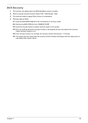
... run normally, the recovery function will auto reboot after the recovery function finished and please enter the setup menu to load default after system reboot. Copy the latest BIOS ROM file to system and then power on the system. 4-4. The recovery media to execute recovery function media: FDD / USB storage / ODD. Recovery step as follow: 4-1. The system will execute 1~3 minutes. 4-6. Rename the BIOS ROM file to be "AMIBOOT.ROM". 4-3. Allow to support Boot...
... run normally, the recovery function will auto reboot after the recovery function finished and please enter the setup menu to load default after system reboot. Copy the latest BIOS ROM file to system and then power on the system. 4-4. The recovery media to execute recovery function media: FDD / USB storage / ODD. Recovery step as follow: 4-1. The system will execute 1~3 minutes. 4-6. Rename the BIOS ROM file to be "AMIBOOT.ROM". 4-3. Allow to support Boot...

Service Guide
Page 63
...shows the location of the mainboard. Jumper CLR_CMOSCLR_CMOS Type 3-pin Description CLEAR CMOS Setting (default) 1-2: NORMAL 2-3: CLEAR Before clearing the CMOS, make sure to set system configuration options. CLR_CMOS ME_DISABLE MEDISABLE 1-2: NORMAL 2-3: MEDISABLE ME_DISABLE Chapter 5 55 Pin 1 is labeled. When setting the jumpers, ensure that the jumper caps are numbered. Jumper Setting The section explains how to turn the system off. Setting Jumper Use the motherboard jumpers to set jumper for correct configuration of the motherboard jumpers. Jumpers with more...
...shows the location of the mainboard. Jumper CLR_CMOSCLR_CMOS Type 3-pin Description CLEAR CMOS Setting (default) 1-2: NORMAL 2-3: CLEAR Before clearing the CMOS, make sure to set system configuration options. CLR_CMOS ME_DISABLE MEDISABLE 1-2: NORMAL 2-3: MEDISABLE ME_DISABLE Chapter 5 55 Pin 1 is labeled. When setting the jumpers, ensure that the jumper caps are numbered. Jumper Setting The section explains how to turn the system off. Setting Jumper Use the motherboard jumpers to set jumper for correct configuration of the motherboard jumpers. Jumpers with more...

Service Guide
Page 64
F_USB1~4: Front Panel USB headers The motherboard has four USB ports installed on connecting the motherboard's optional devices: SATA1~6: Serial ATA connectors These connectors are used to support the new Serial ATA devices for the highest data transfer rates (3.0 Gb/s), simpler disk drive cabling and easier PC assembly. Connecting Optional Devices Refer to the following for information on the rear edge I/O port array. If you 56 Chapter 5 Pin 1 3 5 7 Signal Name Ground TXRXGround 2 4 6 - ?Pin Signal Name TX+ Ground RX+ - Additionally...
F_USB1~4: Front Panel USB headers The motherboard has four USB ports installed on connecting the motherboard's optional devices: SATA1~6: Serial ATA connectors These connectors are used to support the new Serial ATA devices for the highest data transfer rates (3.0 Gb/s), simpler disk drive cabling and easier PC assembly. Connecting Optional Devices Refer to the following for information on the rear edge I/O port array. If you 56 Chapter 5 Pin 1 3 5 7 Signal Name Ground TXRXGround 2 4 6 - ?Pin Signal Name TX+ Ground RX+ - Additionally...

Service Guide
Page 65
... of case, use auxiliary USB connector to connect the front-mounted ports to the motherboard. Chapter 5 57 Pin 1 2 3 4 5 6 7 8 9 10 Signal Name USBPWR me SIN SOUT DTR GND DSR RTS CTS RI NC Data Carrier Detect Serial Input Function UART B Serial Output UART B Data Terminal Ready Ground Data Set Ready RART B Request to Send Clear to digital multimedia device through optical fiber or coaxial connector. Pin 1 2 3 4 5 6 7 8 9 10...
... of case, use auxiliary USB connector to connect the front-mounted ports to the motherboard. Chapter 5 57 Pin 1 2 3 4 5 6 7 8 9 10 Signal Name USBPWR me SIN SOUT DTR GND DSR RTS CTS RI NC Data Carrier Detect Serial Input Function UART B Serial Output UART B Data Terminal Ready Ground Data Set Ready RART B Request to Send Clear to digital multimedia device through optical fiber or coaxial connector. Pin 1 2 3 4 5 6 7 8 9 10...

Service Guide
Page 72
... AM550 USB 4 port bezel for HM090H chassis Hon Hai Aspire Bezel AM551 w/i 3,5"x2 carrier ,USB 4 port bezel for HM090K chassis Card Reader 16-in-1 CR Realtek RTS-5181, 720mm USB cable, for 2010 M5 16-in-1 CR RI236 UT330-LK, 720mm USB cable, for M5 Intel H57 Realtek RTL8111E Giga LAN ATX W/O 1394 LF w/i D-Sub port MB.SDW07.002 Model Name or Key Spec. Aspire M5910(G) FRU List...
... AM550 USB 4 port bezel for HM090H chassis Hon Hai Aspire Bezel AM551 w/i 3,5"x2 carrier ,USB 4 port bezel for HM090K chassis Card Reader 16-in-1 CR Realtek RTS-5181, 720mm USB cable, for 2010 M5 16-in-1 CR RI236 UT330-LK, 720mm USB cable, for M5 Intel H57 Realtek RTL8111E Giga LAN ATX W/O 1394 LF w/i D-Sub port MB.SDW07.002 Model Name or Key Spec. Aspire M5910(G) FRU List...


