
Service Guide
Page 7
...11 Windows Keys 12 Hot Keys 13 Special Keys 14 Hardware Specifications and Configurations 15 System Utilities 25 BIOS Setup Utility 25 Navigating the BIOS Utility 25 Information 26 Main 27 Security 28 Boot 31 Exit 32 BIOS Flash Utility 33 DOS Flash Utility 34 WinFlash Utility 35 Remove HDD/BIOS Password Utilities 36 Removing BIOS Passwords 37 Miscellaneous Utilities 38 Machine Disassembly and Replacement 41 Disassembly Requirements 41 Related Information 41 Replacement Requirements 41 Pre-disassembly Instructions 42 Disassembly Process 43 External Module Disassembly...
...11 Windows Keys 12 Hot Keys 13 Special Keys 14 Hardware Specifications and Configurations 15 System Utilities 25 BIOS Setup Utility 25 Navigating the BIOS Utility 25 Information 26 Main 27 Security 28 Boot 31 Exit 32 BIOS Flash Utility 33 DOS Flash Utility 34 WinFlash Utility 35 Remove HDD/BIOS Password Utilities 36 Removing BIOS Passwords 37 Miscellaneous Utilities 38 Machine Disassembly and Replacement 41 Disassembly Requirements 41 Related Information 41 Replacement Requirements 41 Pre-disassembly Instructions 42 Disassembly Process 43 External Module Disassembly...

Service Guide
Page 8
... Replacing the I/O Card 108 Replacing the Bluetooth Module 110 Replacing the LED Board 111 Replacing the LCD Module 113 Replacing the Button Board 115 Replacing the Upper Cover 118 Replacing the Keyboard 121 Replacing the Wireless LAN Module 122 Replacing the DIMM Module 124 Replacing the Hard Disk Drive 126 Replacing the Battery 128 Replace the Dummy Card 129 Troubleshooting 131 Common Problems 131 Power On Issue 132 No Display Issue 133 Random Loss of BIOS Settings 134 LCD Failure 135 Built-In Keyboard Failure 136 TouchPad Failure 137 Internal...
... Replacing the I/O Card 108 Replacing the Bluetooth Module 110 Replacing the LED Board 111 Replacing the LCD Module 113 Replacing the Button Board 115 Replacing the Upper Cover 118 Replacing the Keyboard 121 Replacing the Wireless LAN Module 122 Replacing the DIMM Module 124 Replacing the Hard Disk Drive 126 Replacing the Battery 128 Replace the Dummy Card 129 Troubleshooting 131 Common Problems 131 Power On Issue 132 No Display Issue 133 Random Loss of BIOS Settings 134 LCD Failure 135 Built-In Keyboard Failure 136 TouchPad Failure 137 Internal...
Service Guide
Page 25
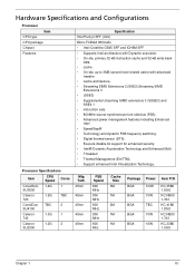
...; Supplemental streaming SIMD extensions 3 (SSSE3) and SSE4.1 • instruction sets. • 800MHz source-synchronous front side bus (FSB) • Advanced power management features including Enhanced Intel • SpeedStep® • Technology and dynamic FSB frequency switching. • Digital thermal sensor (DTS). • Execute disable bit support for enhanced security. • Intel® Dynamic Acceleration Technology and Enhanced Multi • Threaded...
...; Supplemental streaming SIMD extensions 3 (SSSE3) and SSE4.1 • instruction sets. • 800MHz source-synchronous front side bus (FSB) • Advanced power management features including Enhanced Intel • SpeedStep® • Technology and dynamic FSB frequency switching. • Digital thermal sensor (DTS). • Execute disable bit support for enhanced security. • Intel® Dynamic Acceleration Technology and Enhanced Multi • Threaded...

Service Guide
Page 26
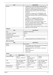
System Memory Item Memory size DIMM socket number Supports memory size per socket Supports maximum memory size Supports DIMM type Supports DIMM Speed Specification 0MB (No on-board Memory) 2 sockets 2GB 4GB for access to GMCH. • PCI Express Base Specification, Revision 1.1 support. • PCI 2.3 interface. (4 PCI Request/Grant pairs). • ACPI Power Management Logi Support. • Enhanced DMA controller, interrupt controller, timers functions. • Integrated Serial ATA host controllers with two 2GB SO-DIMM) DDR2 Synchronous DRAM...
System Memory Item Memory size DIMM socket number Supports memory size per socket Supports maximum memory size Supports DIMM type Supports DIMM Speed Specification 0MB (No on-board Memory) 2 sockets 2GB 4GB for access to GMCH. • PCI Express Base Specification, Revision 1.1 support. • PCI 2.3 interface. (4 PCI Request/Grant pairs). • ACPI Power Management Logi Support. • Enhanced DMA controller, interrupt controller, timers functions. • Integrated Serial ATA host controllers with two 2GB SO-DIMM) DDR2 Synchronous DRAM...
Service Guide
Page 31
... VGA (0.3M) size 1/6" CMOS USB 2.0 high speed interface F2.4 ± 5% 17.4cm ~ Infinity, focus on 40cm Chapter 1 21 Features Item Keyboard Item Type Total number of keypads Windows logo key Internal & external keyboard work simultaneously Features Specification • The AR8131L is compliant with IEEE 802.3u specification for 10/100 Mbps Ethernet and IEEE 802.3ab specification for 1000 Mbps Ethernet. • The AR8131L device combines...
... VGA (0.3M) size 1/6" CMOS USB 2.0 high speed interface F2.4 ± 5% 17.4cm ~ Infinity, focus on 40cm Chapter 1 21 Features Item Keyboard Item Type Total number of keypads Windows logo key Internal & external keyboard work simultaneously Features Specification • The AR8131L is compliant with IEEE 802.3u specification for 10/100 Mbps Ethernet and IEEE 802.3ab specification for 1000 Mbps Ethernet. • The AR8131L device combines...
Service Guide
Page 35
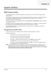
... need to different models. Navigation keys for parameters are six menu options: Information, Main, Advanced, Security, Power, Boot, and Exit. Your computer is prompted on the bottom of the screen. Read this item. • Press Esc while you want to change boot device without entering BIOS Setup Utility, please set to "disabled". Please also refer to enter multi-boot menu. If you are shown on the bottom of F12 Boot Menu is a hardware configuration...
... need to different models. Navigation keys for parameters are six menu options: Information, Main, Advanced, Security, Power, Boot, and Exit. Your computer is prompted on the bottom of the screen. Read this item. • Press Esc while you want to change boot device without entering BIOS Setup Utility, please set to "disabled". Please also refer to enter multi-boot menu. If you are shown on the bottom of F12 Boot Menu is a hardware configuration...

Service Guide
Page 37
... the video memory size. The table below describes the parameters in which the SATA controller should operate. Settings in boldface are displayed with 24hour format. The function allows the user to create a hidden partition on hard disc drive to store operation system and restore the system to 4096MB. Enables, disables the system boot from LAN (remote server). VGA Memory size=32 MB This will hide POST messages while booting. Control the mode in this screen...
... the video memory size. The table below describes the parameters in which the SATA controller should operate. Settings in boldface are displayed with 24hour format. The function allows the user to create a hidden partition on hard disc drive to store operation system and restore the system to 4096MB. Enables, disables the system boot from LAN (remote server). VGA Memory size=32 MB This will hide POST messages while booting. Control the mode in this screen...

Service Guide
Page 38
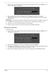
...Press Enter to set the supervisor password. Enter HDD password. Press Enter to set the user or the supervisor password: 28 Chapter 2 The user can enter Setup menu only and does not have three tries before the system halts. Security The Security screen contains parameters that help safeguard and protect your computer from unauthorized access. InsydeH20 Setup Utility Information Main Security Boot Exit S u p e r v i s o r P a s s w o r d:I sC l e a r User Password Is: Clear HDD Password Is: Clear S e t S u p e r v i s o r P a s srwd o Set User Password Set Hdd Password Power...
...Press Enter to set the supervisor password. Enter HDD password. Press Enter to set the user or the supervisor password: 28 Chapter 2 The user can enter Setup menu only and does not have three tries before the system halts. Security The Security screen contains parameters that help safeguard and protect your computer from unauthorized access. InsydeH20 Setup Utility Information Main Security Boot Exit S u p e r v i s o r P a s s w o r d:I sC l e a r User Password Is: Clear HDD Password Is: Clear S e t S u p e r v i s o r P a s srwd o Set User Password Set Hdd Password Power...
Service Guide
Page 39
... New Password v v v 2. Press Enter. Press Enter twice without typing anything in the "Confirm New Password" field. When you are done, press F10 to enable the Password on the screen. 3. Use the and keys to "Set". 4. After setting the password, the computer sets the User Password parameter to highlight the Set Supervisor Password parameter and press the Enter key. The password length can opt to save the changes and exit the BIOS Setup Utility.
... New Password v v v 2. Press Enter. Press Enter twice without typing anything in the "Confirm New Password" field. When you are done, press F10 to enable the Password on the screen. 3. Use the and keys to "Set". 4. After setting the password, the computer sets the User Password parameter to highlight the Set Supervisor Password parameter and press the Enter key. The password length can opt to save the changes and exit the BIOS Setup Utility.
Service Guide
Page 141
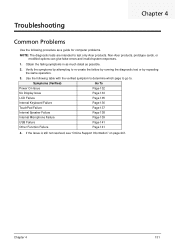
... are intended to test only Acer products. Chapter 4 131 Symptoms (Verified) Go To Power On Issue Page 132 No Display Issue Page 133 LCD Failure Page 135 Internal Keyboard Failure Page 136 TouchPad Failure Page 137 Internal Speaker Failure Page 138 Internal Microphone Failure Page 139 USB Failure Page 141 Other Function Failure Page 141 4. Troubleshooting Chapter 4 Common Problems Use the following table with the...
... are intended to test only Acer products. Chapter 4 131 Symptoms (Verified) Go To Power On Issue Page 132 No Display Issue Page 133 LCD Failure Page 135 Internal Keyboard Failure Page 136 TouchPad Failure Page 137 Internal Speaker Failure Page 138 Internal Microphone Failure Page 139 USB Failure Page 141 Other Function Failure Page 141 4. Troubleshooting Chapter 4 Common Problems Use the following table with the...

Service Guide
Page 144
... the same locations on the screen), the LCD is not running on page 241. See the User Manual for instructions on page 43. 5. Check the display resolution is discovered. 6. e. Click Apply and check the display. Readjust if necessary. 6. Run the Windows Memory Diagnostic from the BIOS, the drive may reduce display brightness. Replace the Motherboard. 134 Chapter 4 If the computer boots correctly, add the devices one by one until the...
... the same locations on the screen), the LCD is not running on page 241. See the User Manual for instructions on page 43. 5. Check the display resolution is discovered. 6. e. Click Apply and check the display. Readjust if necessary. 6. Run the Windows Memory Diagnostic from the BIOS, the drive may reduce display brightness. Replace the Motherboard. 134 Chapter 4 If the computer boots correctly, add the devices one by one until the...

Service Guide
Page 149
... of NG LCD module Swap M/B Microphone Problems If internal or external Microphones do no operate correctly, perform the following actions one at a time to correct the problem. 1. 8. The microphone appears on page 241. Select the microphone then click Properties. If the Issue is still not resolved, see "Online Support Information" on the Recording tab. 4. Remove and recently installed hardware or software. 9. Restore system and file settings from a known good date using System Restore.
... of NG LCD module Swap M/B Microphone Problems If internal or external Microphones do no operate correctly, perform the following actions one at a time to correct the problem. 1. 8. The microphone appears on page 241. Select the microphone then click Properties. If the Issue is still not resolved, see "Online Support Information" on the Recording tab. 4. Remove and recently installed hardware or software. 9. Restore system and file settings from a known good date using System Restore.
Service Guide
Page 150
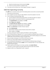
... all cables and jumpers on the HDD and ODD are required. Select Repair your computer. For more information see Windows Help and Support. 10. Replace the HDD. c. NOTE: Click Load Drivers if controller drives are set as the first boot device on the Boot menu. 6. h. When complete, click Finish. Restart the computer and press F2 to locate and resolve issues with the computer. Run the Windows Vista Startup Repair Utility: a. The Install Windows screen displays...
... all cables and jumpers on the HDD and ODD are required. Select Repair your computer. For more information see Windows Help and Support. 10. Replace the HDD. c. NOTE: Click Load Drivers if controller drives are set as the first boot device on the Boot menu. 6. h. When complete, click Finish. Restart the computer and press F2 to locate and resolve issues with the computer. Run the Windows Vista Startup Repair Utility: a. The Install Windows screen displays...
Service Guide
Page 152
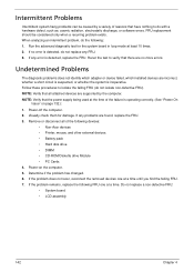
... the failing FRU. 7. Power-off the computer. 2. If the problem remains, replace the following devices: • Non-Acer devices • Printer, mouse, and other external devices • Battery pack • Hard disk drive • DIMM • CD-ROM/Diskette drive Module • PC Cards 4. FRU replacement should be caused by the computer. Undetermined Problems The diagnostic problems does not identify which adapter or device failed, which installed devices are supported by a variety of reasons...
... the failing FRU. 7. Power-off the computer. 2. If the problem remains, replace the following devices: • Non-Acer devices • Printer, mouse, and other external devices • Battery pack • Hard disk drive • DIMM • CD-ROM/Diskette drive Module • PC Cards 4. FRU replacement should be caused by the computer. Undetermined Problems The diagnostic problems does not identify which adapter or device failed, which installed devices are supported by a variety of reasons...
Quick Guide
Page 3
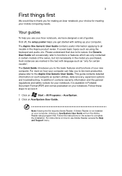
... Aspire product series. For more productive, please refer to complete the installation. Such instances are only contained in certain models of your notebook. It is not installed on your computer, clicking on how your notebook. This guide contains detailed information on your computer can help you use Adobe Reader, access the Help and Support menu. Your guides To help you purchased. Follow the instructions on the screen to the Aspire One Generic User Guide...
... Aspire product series. For more productive, please refer to complete the installation. Such instances are only contained in certain models of your notebook. It is not installed on your computer, clicking on how your notebook. This guide contains detailed information on your computer can help you use Adobe Reader, access the Help and Support menu. Your guides To help you purchased. Follow the instructions on the screen to the Aspire One Generic User Guide...

Quick Guide
Page 7
... indicates the device is USB 2.0 compatible; Click On to disable connection. * Communication devices may vary by model. HDMI port Supports high-definition digital video connections. Click Off to enable Wi-Fi/Bluetooth connection. If a port is black, it is also USB 3.0 compatible. English 7 Using the communication key* Here you can enable and disable the various wireless connectivity devices on your computer. Ethernet (RJ-45) port Connects to a display device (e.g., external port monitor, LCD projector). Left view 1 234 # Icon 1 2 3 4 Item Description External display...
... indicates the device is USB 2.0 compatible; Click On to disable connection. * Communication devices may vary by model. HDMI port Supports high-definition digital video connections. Click Off to enable Wi-Fi/Bluetooth connection. If a port is black, it is also USB 3.0 compatible. English 7 Using the communication key* Here you can enable and disable the various wireless connectivity devices on your computer. Ethernet (RJ-45) port Connects to a display device (e.g., external port monitor, LCD projector). Left view 1 234 # Icon 1 2 3 4 Item Description External display...
User Guide
Page 13
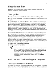
... and release the power button below the LCD screen. Follow these steps to use your Acer notebook, we have designed a set of the power button. For instructions on how to access it contains warranty information and the general regulations and safety notices for the location of guides: First off To turn on AcerSystem User Guide will occasionally refer to "Quick Guide" for your mobile computing needs. This guide contains detailed information...
... and release the power button below the LCD screen. Follow these steps to use your Acer notebook, we have designed a set of the power button. For instructions on how to access it contains warranty information and the general regulations and safety notices for the location of guides: First off To turn on AcerSystem User Guide will occasionally refer to "Quick Guide" for your mobile computing needs. This guide contains detailed information...

User Guide
Page 17
...Cleaning and servicing xv Acer eRecovery Management 1 Acer eRecovery Management 1 Launching Acer eRecovery Management 2 Indicators 3 Touchpad 4 Touchpad basics (with two-click buttons) 4 Using a computer security lock 5 Using the keyboard 6 Lock keys and embedded numeric keypad 6 Windows keys 7 Hotkeys 8 Special keys 9 Frequently asked questions 10 Requesting service 12 International Travelers Warranty (ITW) 12 Before you call 12 Battery pack 13 Battery pack characteristics 13 Maximizing the battery's life 13 Installing and removing the battery pack 14...
...Cleaning and servicing xv Acer eRecovery Management 1 Acer eRecovery Management 1 Launching Acer eRecovery Management 2 Indicators 3 Touchpad 4 Touchpad basics (with two-click buttons) 4 Using a computer security lock 5 Using the keyboard 6 Lock keys and embedded numeric keypad 6 Windows keys 7 Hotkeys 8 Special keys 9 Frequently asked questions 10 Requesting service 12 International Travelers Warranty (ITW) 12 Before you call 12 Battery pack 13 Battery pack characteristics 13 Maximizing the battery's life 13 Installing and removing the battery pack 14...

User Guide
Page 29
... a hard drive. This recovery process helps you purchase your dealer or an authorized service center as the internal keyboard cable may be the only option for future recovery operations. Before performing a restore operation, please check the BIOS settings. 1 Check to see if Acer disk-to-disk recovery is enabled or not. 2 Make sure the D2D Recovery setting in notebook models fitted with the original software content that it works, contact your notebook. The system will be reformatted...
... a hard drive. This recovery process helps you purchase your dealer or an authorized service center as the internal keyboard cable may be the only option for future recovery operations. Before performing a restore operation, please check the BIOS settings. 1 Check to see if Acer disk-to-disk recovery is enabled or not. 2 Make sure the D2D Recovery setting in notebook models fitted with the original software content that it works, contact your notebook. The system will be reformatted...

User Guide
Page 42
... the notebook PC logo is a hardware configuration program built into your computer's BIOS. Your computer is already properly configured and optimized, and you do not need to run this value to Enabled. Enable disk-to-disk recovery To enable disk-to-disk recovery (hard disk recovery), activate the BIOS utility, then select Main from the categories listed at the bottom of the screen and use the and keys to set the boot sequence in the BIOS utility, activate the BIOS utility...
... the notebook PC logo is a hardware configuration program built into your computer's BIOS. Your computer is already properly configured and optimized, and you do not need to run this value to Enabled. Enable disk-to-disk recovery To enable disk-to-disk recovery (hard disk recovery), activate the BIOS utility, then select Main from the categories listed at the bottom of the screen and use the and keys to set the boot sequence in the BIOS utility, activate the BIOS utility...


