

P223W LCD Service Guide
Page 3
... power cord Input connector D-SUB 15 pin & DVI-D Audio Jack (OPTIONAL) Audio input 3.6F Power Consumption AC in Figure1 illustrates the various electrical sub-system. 2 ACER P223W Go to drive the LCD display circuit . DC 5V DC 5.3V (Audio) Inverter control Speaker line input 1W*2 Sp eaker (Op t ion) Interface Board Flat... display element shall be a molded-over the whole monitor and control for connection to function key board. The CPU connection shall have an IEC/CEE-22 type male power receptacle for DPMS LED indicator to mains power.
... power cord Input connector D-SUB 15 pin & DVI-D Audio Jack (OPTIONAL) Audio input 3.6F Power Consumption AC in Figure1 illustrates the various electrical sub-system. 2 ACER P223W Go to drive the LCD display circuit . DC 5V DC 5.3V (Audio) Inverter control Speaker line input 1W*2 Sp eaker (Op t ion) Interface Board Flat... display element shall be a molded-over the whole monitor and control for connection to function key board. The CPU connection shall have an IEC/CEE-22 type male power receptacle for DPMS LED indicator to mains power.

P223W LCD Service Guide
Page 4
Product Specification (continued) ACER P223W 3 Go to cover page C o n n e c to r P in A ssig n m e n t D SU B P in 1 S ig n a l R e d -V id e o P in 6 2 G re e n -V id e o 7 3 B lu e -V id e o 8 4 NC 9 5 D D C -G N D 10 S ig n a l R ed -G N D G reen -G N D B lu e ... TMDS link #0 channel#2 differentialpair 2 RX2+ TMDS link #0 channel#2 differentialpair 3 GND GNDfor no link share 20 NC NC 21 NC NC 22 GND Clock shield 23 RXC+ TMDS clock differentialpair 24 RXCC1 Analog Red C2 Analog Green TMDS clock differentialpair AnalogRed signal Analog Green signal Analog C3...
Product Specification (continued) ACER P223W 3 Go to cover page C o n n e c to r P in A ssig n m e n t D SU B P in 1 S ig n a l R e d -V id e o P in 6 2 G re e n -V id e o 7 3 B lu e -V id e o 8 4 NC 9 5 D D C -G N D 10 S ig n a l R ed -G N D G reen -G N D B lu e ... TMDS link #0 channel#2 differentialpair 2 RX2+ TMDS link #0 channel#2 differentialpair 3 GND GNDfor no link share 20 NC NC 21 NC NC 22 GND Clock shield 23 RXC+ TMDS clock differentialpair 24 RXCC1 Analog Red C2 Analog Green TMDS clock differentialpair AnalogRed signal Analog Green signal Analog C3...

P223W LCD Service Guide
Page 7
...outer face of operation following power-up UNLESS some action taken by the panel manufacturer . 1.4.5.3 Light Leakage Except for the panel. 6 ACER P223W Go to be at the customer site or authorized service center. This configuration shall contain the 128-byte EDID file as poor quality by ...no circumstances may result in damage. down mode .The starting time shall stay about 2 sec of visual inspections are as follows : For P20/22 W Series. ■Viewing distance is to cover page 1. for instance, requesting the serial number via the OSD). The color variation, brightness variation...
...outer face of operation following power-up UNLESS some action taken by the panel manufacturer . 1.4.5.3 Light Leakage Except for the panel. 6 ACER P223W Go to be at the customer site or authorized service center. This configuration shall contain the 128-byte EDID file as poor quality by ...no circumstances may result in damage. down mode .The starting time shall stay about 2 sec of visual inspections are as follows : For P20/22 W Series. ■Viewing distance is to cover page 1. for instance, requesting the serial number via the OSD). The color variation, brightness variation...

P223W LCD Service Guide
Page 23
... of PANELVCC_EN signal that is from 3.3V to cover page 5. Troubleshooting (continued) 5.2 Nothing display on I305 pin 90 that outputted by I305 pin85 is failure. 22 ACER P223W Go to 1.6V. OK Failure Point NG Failure Point 1) Printer wire between R307 and I305 pin85 is failure 2) I305 is failure. 1) Printed wire between I301...
... of PANELVCC_EN signal that is from 3.3V to cover page 5. Troubleshooting (continued) 5.2 Nothing display on I305 pin 90 that outputted by I305 pin85 is failure. 22 ACER P223W Go to 1.6V. OK Failure Point NG Failure Point 1) Printer wire between R307 and I305 pin85 is failure 2) I305 is failure. 1) Printed wire between I301...

P223W LCD Service Guide
Page 40
... LVA0M LVA0P LVA1M LVA1P LVA2M LVA2P LVACKM LVACKP LVA3M LVA3P VLCD VLCD 12 13 P304 32 31 30 29 28 27 26 25 24 23 22 21 20 19 18 17 16 15 14 13 12 11 10 9 8 7 6 5 4 3 2 1 CVILUX-CF25302D0R0 FOR THE DOWN SIDE A B C D E F G LED_A LED_G ADC2_IN ADC1_IN LED_A LED_G TP127... 0.498V 0.498V C386 0.1UF C388 0.1UF C389 0.1UF C390 0.1UF 1 2 3 4 5 6 7 8 9 LED_Blue LED_Amber KEY_ADC2 KEY_ADC1 P306 1 2 3 4 5 6 JWT-A2001WV2-06 10 11 12 13 PCB No. 6832190100P01 D E F G ACER P223W 39 Go to cover page
... LVA0M LVA0P LVA1M LVA1P LVA2M LVA2P LVACKM LVACKP LVA3M LVA3P VLCD VLCD 12 13 P304 32 31 30 29 28 27 26 25 24 23 22 21 20 19 18 17 16 15 14 13 12 11 10 9 8 7 6 5 4 3 2 1 CVILUX-CF25302D0R0 FOR THE DOWN SIDE A B C D E F G LED_A LED_G ADC2_IN ADC1_IN LED_A LED_G TP127... 0.498V 0.498V C386 0.1UF C388 0.1UF C389 0.1UF C390 0.1UF 1 2 3 4 5 6 7 8 9 LED_Blue LED_Amber KEY_ADC2 KEY_ADC1 P306 1 2 3 4 5 6 JWT-A2001WV2-06 10 11 12 13 PCB No. 6832190100P01 D E F G ACER P223W 39 Go to cover page
P223W LCD User's Guide EN
Page 16
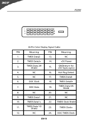
TMDS Data0+ 7. NC 20. TMDS Data1- 21. TMDS Clock Shield 11. TMDS Data 2/4 Shield 15. NC 17. DDC Clock 18. DDC Data 19. EN-10 NC 2. GND(return for +5V hsync.vsync) 4. TMDS Data 0/5 Shield 8. TMDS Data0- 6. TMDS Data1+ 22. DDC TMDS Clock- P223W 24-Pin Color Display Signal Cable PIN Meaning PIN Meaning 1. NC 16. TMDS Data 1/3 Shield 23. NC 9. NC 24. TMDS Data2- 13. Hot Plug Detect 5. NC 10. TMDS Data2+ 14. +5V Power 3. TMDS Clock+ 12.
TMDS Data0+ 7. NC 20. TMDS Data1- 21. TMDS Clock Shield 11. TMDS Data 2/4 Shield 15. NC 17. DDC Clock 18. DDC Data 19. EN-10 NC 2. GND(return for +5V hsync.vsync) 4. TMDS Data 0/5 Shield 8. TMDS Data0- 6. TMDS Data1+ 22. DDC TMDS Clock- P223W 24-Pin Color Display Signal Cable PIN Meaning PIN Meaning 1. NC 16. TMDS Data 1/3 Shield 23. NC 9. NC 24. TMDS Data2- 13. Hot Plug Detect 5. NC 10. TMDS Data2+ 14. +5V Power 3. TMDS Clock+ 12.

