

P223W LCD Service Guide
Page 2
...master power switch each time before performing the service procedures. To ensure the continued reliability of notices listed in assembly and disassembly procedures to well mounted the parts. ! The service providers recommended by vender should be connect to minimize the risk of...assumes no liability express or implied, arising out of any unauthorized modification of personal injury when perform service procedures. Important Safety Notice ACER P223W 1 Go to cover page Product Anouncement: This product is certificated to replace defective parts. To prevent the product away from ...
...master power switch each time before performing the service procedures. To ensure the continued reliability of notices listed in assembly and disassembly procedures to well mounted the parts. ! The service providers recommended by vender should be connect to minimize the risk of...assumes no liability express or implied, arising out of any unauthorized modification of personal injury when perform service procedures. Important Safety Notice ACER P223W 1 Go to cover page Product Anouncement: This product is certificated to replace defective parts. To prevent the product away from ...

P223W LCD Service Guide
Page 13
....1~4 screws till that power board and bracket chassis base firmly attached.(No1 screw size=M4x8; No2~4 screw size=M3x6; 12 ACER P223W Go to the connector of bracket chassis base. Assembly and Disassembly Procedures 4.1 Assembly procedures: Connect the cable between power board(P802) S1 and interface board (P301) Connect the function key cable...
....1~4 screws till that power board and bracket chassis base firmly attached.(No1 screw size=M4x8; No2~4 screw size=M3x6; 12 ACER P223W Go to the connector of bracket chassis base. Assembly and Disassembly Procedures 4.1 Assembly procedures: Connect the cable between power board(P802) S1 and interface board (P301) Connect the function key cable...

P223W LCD Service Guide
Page 14
4. Assembly and Disassembly Procedures (continued) ACER P223W 13 Go to cover page S8 Connect FFC cable to key function cable. 1 2 There are two locks over here when plugging in parallel direction S8 ...
4. Assembly and Disassembly Procedures (continued) ACER P223W 13 Go to cover page S8 Connect FFC cable to key function cable. 1 2 There are two locks over here when plugging in parallel direction S8 ...

P223W LCD Service Guide
Page 15
... on force mechanisms locked and firmly attached. 14 ACER P223W Go to cover the LCD monitor. one is held the front side of screwing 4 screws till both two sides S16 S20 Take two cushion foams; S19 Take a LDPE+EPE bag to cover page 4. Assembly and Disassembly Procedures (continued) S14 Put a rear cover on...
... on force mechanisms locked and firmly attached. 14 ACER P223W Go to cover the LCD monitor. one is held the front side of screwing 4 screws till both two sides S16 S20 Take two cushion foams; S19 Take a LDPE+EPE bag to cover page 4. Assembly and Disassembly Procedures (continued) S14 Put a rear cover on...

P223W LCD Service Guide
Page 16
4. Assembly and Disassembly Procedures (continued) S21 Put accessories of stand, DVI cable, and user's manual ,power cable on the carton then packing the carton FEATURE LABEL VISTA LABEL USER'S MANUAL ACER P223W 15 Go to cover page POWER CABLE DVI CABLE STAND D-SUB CABLE S22 Move previous assembled parts into the carton then stick Vista and feature label on specific positions as photo below.
4. Assembly and Disassembly Procedures (continued) S21 Put accessories of stand, DVI cable, and user's manual ,power cable on the carton then packing the carton FEATURE LABEL VISTA LABEL USER'S MANUAL ACER P223W 15 Go to cover page POWER CABLE DVI CABLE STAND D-SUB CABLE S22 Move previous assembled parts into the carton then stick Vista and feature label on specific positions as photo below.

P223W LCD Service Guide
Page 17
... a Phillips-head screwdriver unscrew 4 screws S6 to cover page 4. Assembly and Disassembly Procedures (continued) 4.2 Disassembly procedures Open the carton with a proper tool. S1 FEATURE LABEL S4 Put returned unit on whether users returning the accessories.) USER'S MANUAL Disassemble the stand cover. S7 16 ACER P223W Go to release the stand base. (No1~4 Screw Size=M4x10;
... a Phillips-head screwdriver unscrew 4 screws S6 to cover page 4. Assembly and Disassembly Procedures (continued) 4.2 Disassembly procedures Open the carton with a proper tool. S1 FEATURE LABEL S4 Put returned unit on whether users returning the accessories.) USER'S MANUAL Disassemble the stand cover. S7 16 ACER P223W Go to release the stand base. (No1~4 Screw Size=M4x10;
P223W LCD Service Guide
Page 18
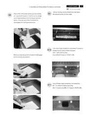
... Work your finger between the front bezel and the panel, then pry up on to lease power plug (No1~2 screw size=M3x10; Assembly and Disassembly Procedures (continued) ACER P223W 17 Go to cover page Place cloth on the panel where you are working S8 on the front bezel to disengage all the locking...
... Work your finger between the front bezel and the panel, then pry up on to lease power plug (No1~2 screw size=M3x10; Assembly and Disassembly Procedures (continued) ACER P223W 17 Go to cover page Place cloth on the panel where you are working S8 on the front bezel to disengage all the locking...

P223W LCD Service Guide
Page 19
18 ACER P223W Go to the connector of panel. Torque=3~4KGFxCM). S15 Disconnect the FFC cable to cover page 4. S13 Examine the panel surface accoring to disassemble the LCD panel and bracket chassis module. (No1~4 screw size=M3x6; Torque=9~10KGFxCM). 1 2 3 2 4 1 Assembly and Disassembly Procedures (continued) S12 Use a Phillips-head screwdriver unscrewed the No.1~4 screws to...
18 ACER P223W Go to the connector of panel. Torque=3~4KGFxCM). S15 Disconnect the FFC cable to cover page 4. S13 Examine the panel surface accoring to disassemble the LCD panel and bracket chassis module. (No1~4 screw size=M3x6; Torque=9~10KGFxCM). 1 2 3 2 4 1 Assembly and Disassembly Procedures (continued) S12 Use a Phillips-head screwdriver unscrewed the No.1~4 screws to...

P223W LCD Service Guide
Page 20
Torque=9~10KGFxCM). 3 2 ACER P223W 19 Go to cover page 4 1 Disconnect the FFC, P301, and function key S19 cables to disassemble the power board. (No1 screw size=M4x8; P802 P301 FFC P306 4. No2~4 screw size=M3x6; Assembly and Disassembly Procedures (continued) S18 Use a Phillips-head screwdriver unscrewed the No.1~4 screws to connectors of interface board.
Torque=9~10KGFxCM). 3 2 ACER P223W 19 Go to cover page 4 1 Disconnect the FFC, P301, and function key S19 cables to disassemble the power board. (No1 screw size=M4x8; P802 P301 FFC P306 4. No2~4 screw size=M3x6; Assembly and Disassembly Procedures (continued) S18 Use a Phillips-head screwdriver unscrewed the No.1~4 screws to connectors of interface board.


