User Manual
Page 4
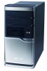
... a qualified technician to restore the product to qualified service personnel. Refer all servicing to normal condition. If power strips are covered by the operating instructions, since improper adjustment of this product. • Use the product only with a three-wire grounded plug. Contact your electrician for service • the product does not operate normally after following requirements: detachable type, UL listed/CSA certified, type SPT-2, rated...
... a qualified technician to restore the product to qualified service personnel. Refer all servicing to normal condition. If power strips are covered by the operating instructions, since improper adjustment of this product. • Use the product only with a three-wire grounded plug. Contact your electrician for service • the product does not operate normally after following requirements: detachable type, UL listed/CSA certified, type SPT-2, rated...
User Manual
Page 10
... 41 Connecting a monitor 42 Connecting the power cable 43 Turning on your computer 44 Turning off your computer 44 Connecting options 45 Connecting your printer 45 Connecting the modem (optional) 46 Connecting to the network 46 Connecting multimedia devices 47 Connecting USB devices 49 4 Upgrading your computer 51 Installation precautions 53 ESD precautions 53 Preinstallation instructions 53 Post-installation instructions 54 Opening your Veriton 5900Pro 55 To remove the computer cover 55 To replace the computer cover 55 Opening your...
... 41 Connecting a monitor 42 Connecting the power cable 43 Turning on your computer 44 Turning off your computer 44 Connecting options 45 Connecting your printer 45 Connecting the modem (optional) 46 Connecting to the network 46 Connecting multimedia devices 47 Connecting USB devices 49 4 Upgrading your computer 51 Installation precautions 53 ESD precautions 53 Preinstallation instructions 53 Post-installation instructions 54 Opening your Veriton 5900Pro 55 To remove the computer cover 55 To replace the computer cover 55 Opening your...

User Manual
Page 15
... reset it except by optimizing disk space, memory and registry settings. • Acer eAcoustics Management offers a useful tool to balance your computing power needs with your desired level of your screen, it easy for the first time. 3 Acer Empowering Technology Acer's innovative Empowering Technology toolbar makes it features the following handy utilities: • Acer eSettings Management accesses system information and adjusts settings easily. • Acer eLock Management limits access to external storage media...
... reset it except by optimizing disk space, memory and registry settings. • Acer eAcoustics Management offers a useful tool to balance your computing power needs with your desired level of your screen, it easy for the first time. 3 Acer Empowering Technology Acer's innovative Empowering Technology toolbar makes it features the following handy utilities: • Acer eSettings Management accesses system information and adjusts settings easily. • Acer eLock Management limits access to external storage media...

User Manual
Page 17
... Acer eLock Management, a password must be mounted as a file system when plugged into the system. • Optical drive devices - includes USB disk drives, USB pen drives, USB flash drives, USB MP3 drives, USB memory card readers, IEEE 1394 disk drives and any other removable disk drives that data can apply locks to any reboot necessary, and will immediately be stolen while your computer is no method to an Acer Customer Service Center. Note: If you can 't be set without any of DVD-ROM drives...
... Acer eLock Management, a password must be mounted as a file system when plugged into the system. • Optical drive devices - includes USB disk drives, USB pen drives, USB flash drives, USB MP3 drives, USB memory card readers, IEEE 1394 disk drives and any other removable disk drives that data can apply locks to any reboot necessary, and will immediately be stolen while your computer is no method to an Acer Customer Service Center. Note: If you can 't be set without any of DVD-ROM drives...
User Manual
Page 33
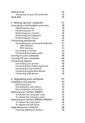
... quality audio system via onboard audio controller • Audio-in/line-in, audio-out/line-out, headphone-out and microphone-in interfaces Connectivity • Two PS/2 interfaces for mouse and keyboard • One serial port (optional 2nd serial port connection) • One parallel port • One VGA port • Eight Universal Serial Bus (USB) 2.0 ports (four on the rear panel) • High-speed V.92, 56K fax/modem (manufacturing option) • Gigabit Ethernet LAN support with remote wake-up function...
... quality audio system via onboard audio controller • Audio-in/line-in, audio-out/line-out, headphone-out and microphone-in interfaces Connectivity • Two PS/2 interfaces for mouse and keyboard • One serial port (optional 2nd serial port connection) • One parallel port • One VGA port • Eight Universal Serial Bus (USB) 2.0 ports (four on the rear panel) • High-speed V.92, 56K fax/modem (manufacturing option) • Gigabit Ethernet LAN support with remote wake-up function...
User Manual
Page 38
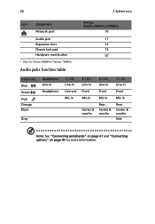
...-in Line-out Mic-in 3.1 CH Line-in Front Mic-in Center & woofer 5.1 CH Line-in Front Mic-in Rear Center & woofer 7.1 CH Line-in Front Mic-in Rear Center & woofer Side Note: See "Connecting peripherals" on page 41 and "Connecting options" on page 45 for more information. 26 2 System tour Icon Component Network port Audio jack Expansion slots Chassis lock pad Hardware reset button *.
...-in Line-out Mic-in 3.1 CH Line-in Front Mic-in Center & woofer 5.1 CH Line-in Front Mic-in Rear Center & woofer 7.1 CH Line-in Front Mic-in Rear Center & woofer Side Note: See "Connecting peripherals" on page 41 and "Connecting options" on page 45 for more information. 26 2 System tour Icon Component Network port Audio jack Expansion slots Chassis lock pad Hardware reset button *.
User Manual
Page 53
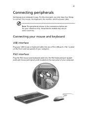
... mouse port (green port) located on the front and rear panels of your computer. 41 Connecting peripherals Setting up your reference only. Note: The peripherals shown in select countries. located PS/2 interface Plug the PS/2 mouse and keyboard cable into any of the USB ports on the rear panel of your computer. For the most part, you only have four things to connect: the mouse, the keyboard, the monitor, and the power cable. Actual device models...
... mouse port (green port) located on the front and rear panels of your computer. 41 Connecting peripherals Setting up your reference only. Note: The peripherals shown in select countries. located PS/2 interface Plug the PS/2 mouse and keyboard cable into any of the USB ports on the rear panel of your computer. For the most part, you only have four things to connect: the mouse, the keyboard, the monitor, and the power cable. Actual device models...
User Manual
Page 54
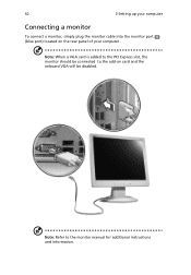
Note: Refer to the add-on the rear panel of your computer . Note: When a VGA card is added to the PCI Express slot, the monitor should be disabled. 42 3 Setting up your computer Connecting a monitor To connect a monitor, simply plug the monitor cable into the monitor port (blue port) located on card and the onboard VGA will be connected to the monitor manual for additional instructions and information.
Note: Refer to the add-on the rear panel of your computer . Note: When a VGA card is added to the PCI Express slot, the monitor should be disabled. 42 3 Setting up your computer Connecting a monitor To connect a monitor, simply plug the monitor cable into the monitor port (blue port) located on card and the onboard VGA will be connected to the monitor manual for additional instructions and information.

User Manual
Page 58
Note: Consult your network system administrator or operating system manual for information on how to configure your computer. To do so, simply plug the network cable into their corresponding ports on the rear panel of Connecting to the network You can connect your computer. into the network port on the rear panel of your network setup. 46 3 Setting up your computer Connecting the modem (optional) Set up your modem connection by plugging the telephone line and handset line your computer to a Local Area Network (LAN) using a network cable.
Note: Consult your network system administrator or operating system manual for information on how to configure your computer. To do so, simply plug the network cable into their corresponding ports on the rear panel of Connecting to the network You can connect your computer. into the network port on the rear panel of your network setup. 46 3 Setting up your computer Connecting the modem (optional) Set up your modem connection by plugging the telephone line and handset line your computer to a Local Area Network (LAN) using a network cable.

User Manual
Page 61
... computer. To connect a USB device, simply plug the device cable into any of the USB ports (black) located on the rear panel. They also allow you to connect additional USB devices to the audio-in/line-in jack jack) located on the rear panel of your computer (light blue Connecting USB devices Universal Serial Bus (USB) is a serial bus design capable of your computer without using up its resources. These ports support USB 2.0 high-performance external devices such as a digital camera, keyboard, mouse, joystick...
... computer. To connect a USB device, simply plug the device cable into any of the USB ports (black) located on the rear panel. They also allow you to connect additional USB devices to the audio-in/line-in jack jack) located on the rear panel of your computer (light blue Connecting USB devices Universal Serial Bus (USB) is a serial bus design capable of your computer without using up its resources. These ports support USB 2.0 high-performance external devices such as a digital camera, keyboard, mouse, joystick...
User Manual
Page 65
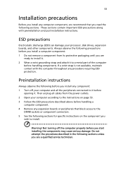
... the computer properly before handling a computer component. 4 Remove any component: 1 Turn off your processor, disk drives, expansion boards, and other components. Then unplug all the peripherals connected to it before opening it to a metal part of the computer before you are ready to the instructions on the component you wish to the DIMM sockets or component connectors. 5 See the following sections.
... the computer properly before handling a computer component. 4 Remove any component: 1 Turn off your processor, disk drives, expansion boards, and other components. Then unplug all the peripherals connected to it before opening it to a metal part of the computer before you are ready to the instructions on the component you wish to the DIMM sockets or component connectors. 5 See the following sections.

User Manual
Page 66
54 4 Upgrading your computer Post-installation instructions Observe the following after installing a computer component: 1 See to it that the components are installed according to the step-by-step instructions in their respective sections. 2 Replace any expansion boards or peripherals that you removed earlier. 3 Replace the side panels. 4 Connect the necessary cables and turn on your computer.
54 4 Upgrading your computer Post-installation instructions Observe the following after installing a computer component: 1 See to it that the components are installed according to the step-by-step instructions in their respective sections. 2 Replace any expansion boards or peripherals that you removed earlier. 3 Replace the side panels. 4 Connect the necessary cables and turn on your computer.

User Manual
Page 70
... configurations. If you to install DDR2 DIMMs with different capacities to replace or upgrade any of these upgrades yourself. Note: DDR2 667/800, 4 DIMM slots, expandable to observe the "Installation precautions" on the mainboard support Double Data Rate 2 (DDR2) Synchronous Dynamic Random Access Memory (SDRAM)-type DIMMs. You may not be exactly the same as the memory, the hard disk, the CPU and the expansion cards...
... configurations. If you to install DDR2 DIMMs with different capacities to replace or upgrade any of these upgrades yourself. Note: DDR2 667/800, 4 DIMM slots, expandable to observe the "Installation precautions" on the mainboard support Double Data Rate 2 (DDR2) Synchronous Dynamic Random Access Memory (SDRAM)-type DIMMs. You may not be exactly the same as the memory, the hard disk, the CPU and the expansion cards...

User Manual
Page 72
... the hard disk out. 3 Remove the drive rails that the other ends of the disk cables are securely connected to their corresponding connectors on the mainboard. Installing an expansion card To install an expansion card: 1 Remove the computer cover. 2 Locate an empty PCI Express or PCI slot on the mainboard. 6 Reinstall the metal bracket frame to the new hard disk. Run the BIOS utility to view the new value for total system memory and make a note of memory installed.
... the hard disk out. 3 Remove the drive rails that the other ends of the disk cables are securely connected to their corresponding connectors on the mainboard. Installing an expansion card To install an expansion card: 1 Remove the computer cover. 2 Locate an empty PCI Express or PCI slot on the mainboard. 6 Reinstall the metal bracket frame to the new hard disk. Run the BIOS utility to view the new value for total system memory and make a note of memory installed.

User Manual
Page 75
... panel. See "To replace the side panel" on the computer, BIOS automatically detects and assigns resources to the computer. 4 Pull out the bracket on the housing opposite the selected empty slot. 5 Remove the expansion card from its protective packaging. 6 Align the card with the bracket lock you turn on page 57. Make sure that holds the bracket to the newly installed devices...
... panel. See "To replace the side panel" on the computer, BIOS automatically detects and assigns resources to the computer. 4 Pull out the bracket on the housing opposite the selected empty slot. 5 Remove the expansion card from its protective packaging. 6 Align the card with the bracket lock you turn on page 57. Make sure that holds the bracket to the newly installed devices...

User Manual
Page 85
... Alt + F10 after the BIOS finishes running will restore your system quick and easy. Warning: Initiating the recovery operation while the operating system is from a hidden partition on your hard drive that makes restoring your system's original factory default settings or last system backup. This utility has same password protection with Acer eRecovery. After the POST runs, Press Alt + F10 combine key during BIOS to restore your system. 73 Recovering your...
... Alt + F10 after the BIOS finishes running will restore your system quick and easy. Warning: Initiating the recovery operation while the operating system is from a hidden partition on your hard drive that makes restoring your system's original factory default settings or last system backup. This utility has same password protection with Acer eRecovery. After the POST runs, Press Alt + F10 combine key during BIOS to restore your system. 73 Recovering your...

User Manual
Page 95
... any key to the system. Insert the startup disk you are using a power strip or AVR, make necessary fixes. If restarting your dealer or technical support center for assistance. I pressed the power switch but the system did not boot up. If the LED is not lit, no power is lit, check the following questions indicate possible situations that may arise during Windows setup into the floppy drive...
... any key to the system. Insert the startup disk you are using a power strip or AVR, make necessary fixes. If restarting your dealer or technical support center for assistance. I pressed the power switch but the system did not boot up. If the LED is not lit, no power is lit, check the following questions indicate possible situations that may arise during Windows setup into the floppy drive...

User Manual
Page 96
... or external speakers are connected to the system's parallel or USB port and the corresponding port on . • Make sure the printer cable is turned on the printer. 84 6 Frequently asked questions The printer does not work. If it is connected securely to the lineout jack of disk or diskette. Contact your printer" on the good disk there may be a problem with the drive. Look...
... or external speakers are connected to the system's parallel or USB port and the corresponding port on . • Make sure the printer cable is turned on the printer. 84 6 Frequently asked questions The printer does not work. If it is connected securely to the lineout jack of disk or diskette. Contact your printer" on the good disk there may be a problem with the drive. Look...
User Manual
Page 101
...power failure conditions this equipment is designed. It indicates no responsibility should NOT contact the telecom Fault Service. 8 This equipment may not operate. Telecom will always continue to Telecom's 111 Emergency Service. 6 This device is equipped with this device. Should such problems occur, the user should difficulties arise in all operating conditions, of correct operation at the higher speeds for connection to different numbers...5 This equipment shall not be set up to make or model, nor does it imply that any item will work correctly in such circumstances. 3 ...
...power failure conditions this equipment is designed. It indicates no responsibility should NOT contact the telecom Fault Service. 8 This equipment may not operate. Telecom will always continue to Telecom's 111 Emergency Service. 6 This device is equipped with this device. Should such problems occur, the user should difficulties arise in all operating conditions, of correct operation at the higher speeds for connection to different numbers...5 This equipment shall not be set up to make or model, nor does it imply that any item will work correctly in such circumstances. 3 ...

User Manual
Page 107
... A accessing the online User's Guide 17 applications 67 B BIOS utility 72 C computer cover remove 55 replace 55 connecting options multimedia devices 47 audio line-in device 49 earphones/headphones 48 external speakers 47 microphone 47 network 45, 46 printer 45 serial mouse 46 USB devices 49 D disk drives CD-ROM/DVD-ROM/CD-RW drive inserting CDs/DVDs 32 taking care CDs/DVDs 35 hard disk 35 F features 21 connectivity 21 multimedia 21 performance 21 Frequently-asked questions 83 blank screen 83...
... A accessing the online User's Guide 17 applications 67 B BIOS utility 72 C computer cover remove 55 replace 55 connecting options multimedia devices 47 audio line-in device 49 earphones/headphones 48 external speakers 47 microphone 47 network 45, 46 printer 45 serial mouse 46 USB devices 49 D disk drives CD-ROM/DVD-ROM/CD-RW drive inserting CDs/DVDs 32 taking care CDs/DVDs 35 hard disk 35 F features 21 connectivity 21 multimedia 21 performance 21 Frequently-asked questions 83 blank screen 83...


